EP0924635A2 - Système électronique d'identification avec un lecteur et une pluralité de transpondeurs - Google Patents
Système électronique d'identification avec un lecteur et une pluralité de transpondeurs Download PDFInfo
- Publication number
- EP0924635A2 EP0924635A2 EP98310249A EP98310249A EP0924635A2 EP 0924635 A2 EP0924635 A2 EP 0924635A2 EP 98310249 A EP98310249 A EP 98310249A EP 98310249 A EP98310249 A EP 98310249A EP 0924635 A2 EP0924635 A2 EP 0924635A2
- Authority
- EP
- European Patent Office
- Prior art keywords
- signal
- transponder
- flag
- reset
- amplitude
- Prior art date
- Legal status (The legal status is an assumption and is not a legal conclusion. Google has not performed a legal analysis and makes no representation as to the accuracy of the status listed.)
- Withdrawn
Links
Images


Classifications
-
- G—PHYSICS
- G06—COMPUTING OR CALCULATING; COUNTING
- G06K—GRAPHICAL DATA READING; PRESENTATION OF DATA; RECORD CARRIERS; HANDLING RECORD CARRIERS
- G06K7/00—Methods or arrangements for sensing record carriers, e.g. for reading patterns
- G06K7/10—Methods or arrangements for sensing record carriers, e.g. for reading patterns by electromagnetic radiation, e.g. optical sensing; by corpuscular radiation
- G06K7/10009—Methods or arrangements for sensing record carriers, e.g. for reading patterns by electromagnetic radiation, e.g. optical sensing; by corpuscular radiation sensing by radiation using wavelengths larger than 0.1 mm, e.g. radio-waves or microwaves
- G06K7/10019—Methods or arrangements for sensing record carriers, e.g. for reading patterns by electromagnetic radiation, e.g. optical sensing; by corpuscular radiation sensing by radiation using wavelengths larger than 0.1 mm, e.g. radio-waves or microwaves resolving collision on the communication channels between simultaneously or concurrently interrogated record carriers.
- G06K7/10029—Methods or arrangements for sensing record carriers, e.g. for reading patterns by electromagnetic radiation, e.g. optical sensing; by corpuscular radiation sensing by radiation using wavelengths larger than 0.1 mm, e.g. radio-waves or microwaves resolving collision on the communication channels between simultaneously or concurrently interrogated record carriers. the collision being resolved in the time domain, e.g. using binary tree search or RFID responses allocated to a random time slot
- G06K7/10039—Methods or arrangements for sensing record carriers, e.g. for reading patterns by electromagnetic radiation, e.g. optical sensing; by corpuscular radiation sensing by radiation using wavelengths larger than 0.1 mm, e.g. radio-waves or microwaves resolving collision on the communication channels between simultaneously or concurrently interrogated record carriers. the collision being resolved in the time domain, e.g. using binary tree search or RFID responses allocated to a random time slot interrogator driven, i.e. synchronous
-
- G—PHYSICS
- G06—COMPUTING OR CALCULATING; COUNTING
- G06K—GRAPHICAL DATA READING; PRESENTATION OF DATA; RECORD CARRIERS; HANDLING RECORD CARRIERS
- G06K7/00—Methods or arrangements for sensing record carriers, e.g. for reading patterns
- G06K7/0008—General problems related to the reading of electronic memory record carriers, independent of its reading method, e.g. power transfer
Definitions
- This invention relates to electronic identification systems and more particularly to an electronic identification system including a reader and a plurality of transponders.
- Identification systems including a reader or interrogator and a plurality of transponders are known in the art.
- the transponders in these systems utilize energy in an energizing signal transmitted by the reader or interrogator to charge respective local virtual batteries including charge storage capacitors, to power electronic circuits of the transponder.
- the transponders when initially powered-up as aforesaid, are in an active mode, so that they all automatically respond by modulating the energizing signal by backscatter modulation with data prestored in the respective transponders.
- the data is modulated by each transponder in frames separated by an inter-frame interval and at a rate determined by a frequency of a clock on the transponder.
- the reader locks onto the clock frequency of one transponder, reads the data and transmits an acknowledgement signal.
- the acknowledgement signal is utilized by the transponder just read to switch it to a sleep mode wherein it is inhibited from responding to the energizing signal, even while still being energized.
- the interrogator then locks onto the clock frequency of a next transponder in the energizing radiation pattern and the aforementioned procedure is repeated for that transponder, so that it is also read and switched to the sleep mode.
- the duration of the sleep mode is in some cases determined by an internal reset timer of the transponder. In other cases, it may be indeterminate in that it is dependent on a discharge time of the charge storage capacitor on the transponder.
- the transponder When the capacitor is discharged, the transponder automatically resets to the active mode. Thus, while the transponder is still energized and in the sleep mode, it cannot be woken up again, until the term of the sleep mode has expired.
- the energization is removed and the aforementioned capacitor has discharged (typically 10 - 20 seconds after the energizing field has been removed) the transponder automatically resets to the aforementioned active mode. This is not satisfactory in many applications.
- the transponder For example, and mainly due to the charge storage limitation imposed by the size of a capacitor on a transponder which is embodied in the form of an integrated circuit, it is not possible practically to support a so-called electronic article surveillance procedure with the aforementioned system. As stated hereinbefore, after removal of the energizing field from the transponder, sufficient charge to power the transponder will remain on the capacitor for 10 to 20 seconds only, after which the transponder automatically resets to the active mode. For most electronic article surveillance procedures (for example those applied at an exit of a store or shop), the transponder needs to be kept in the sleep mode for a number of minutes at least, typically for one to three hours.
- the interrogator reads these transponders one by one and they are identified by their unique identification numbers.
- the sub-set as a whole once ready can similarly be unselected and another sub-set can then similarly be selected.
- a method of reading a transponder population including a plurality of electronic transponders including the steps of:
- the energizing signal may be in the form of a high frequency carrier and the acknowledgement signal may be in the form of a pulse, amplitude modulated on the carrier.
- the reset signal may also be amplitude modulated on the carrier.
- the method may also include the steps of causing the transponders to utilize respective command decoders to decode command signals which are to decode command signals which are amplitude modulated on the energizing signal; and to utilizing the decoded signals to select a selectable parameter of transponder operation.
- the invention also provides an electronic transponder for an electronic identification system also including a reader for reading the transponder, the transponder including:
- the resetable flag preferably includes a bistable, non-volatile memory cell.
- the mode selection detection circuitry may include a reset signal detector including a low pass filter for filtering out the reset signal which is amplitude modulated on the energizing signal.
- the reset signal detector may further include an amplitude demodulator connected to an input of the low pass filter.
- the demodulator may include an envelope detector and the low pass filter may include an integrator.
- An output of the integrator may be connected to a rectifier, to yield a rectified signal having an amplitude which is proportional to an amplitude of a signal at an output of the integrator; and the output of the rectifier may be connected to a comparator circuit, for providing an output signal to reset the flag, if the amplitude of the rectified signal is in a predetermined relation to a first reference signal supplied to the comparator.
- the integrator may have a transfer function with a negative slope of amplitude against increasing frequency; and the comparator may be configured to provide a second output signal in response to a second input signal having a frequency falling on the slope, if the output signal at the output of the rectifier derived from the second input signal is in a predetermined relation to a second reference signal.
- the invention further provides an electronic identification system including:
- the acknowledgement signal may be in the form of a pulse, which is amplitude modulated on the energizing signal.
- the transmitter of the reader preferably amplitude modulates the reset signal on the energizing signal and the frequency of the reset signal is preferably at least an order lower than the frequency components of the acknowledgement signal and of the energizing signal.
- the present invention also provides transponder command signal detection circuitry including:
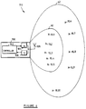
- the illustrated embodiment of the invention relates to an electronic identification system 110 including a reader 100 shown in Figure 6 and a transponder population including a plurality of transponders 10.1 to 10.10.
- the embodiment more particularly relates to the first family of identification systems described in the introduction to this specification.
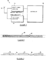
- the reader 100 includes a controller 102, a radio frequency transmitter 104 for transmitting an energizing signal 80 in the form of a high frequency carrier (shown in Figure 8) to the transponder population; and a receiver 106 for receiving response signals (shown in Figure 9) from the transponders.
- the transmitter and receiver are connected in known manner to an antenna 108.
- a high frequency carrier/energizing signal 80 (10KHz to 2.5 GHz) is utilized by the reader.
- the acknowledgement signal 82, a reset signal 37 and other command signals are amplitude modulated on the carrier.
- the frequency components of the carrier and acknowledgement signals are at least one order higher than the frequency components of the reset signal and other command or programming signals.
- each transponder 10 includes an antenna 12 and a modulator 14 which is controlled by logic circuitry 16 to backscatter modulate the energizing signal 80 received from a reader 100, to transmit response data stored in a transmit shift register 17 back to the reader.
- the logic circuitry includes a clock signal generator 19 and means 21 for arranging the response data in discrete frames 90 to 94, shown in Figure 9.
- the clock frequency determines the data rate in the response.
- the interframe interval 96 (see Figure 9) may be selectable as hereinafter described.
- a virtual battery 18 including a capacitor (also not shown) serves to collect power from the energizing signal 80 and to power the circuitry of the transponder 10.
- the transponder 10 further includes a non-volatile resetable sleep flag 20 in the form of a bistable memory cell, which when set, causes the transponder not to respond to the energizing signal as aforesaid.
- the flag 20 is set by an acknowledgement signal 82.
- the acknowledgement signal is in the form of a precisely timed pulse, amplitude modulated by the reader 100 on the carrier 80 and which signal is received via antenna 12 of the transponder and detected by a detector circuit 22 forming part of mode selection signal detection circuitry 23 of the transponder.
- the acknowledgement signal 82 is transmitted by the reader 100 immediately after a transponder of the population has been read, indicating to the transponder just read that the responding signal has been received by the reader and the data (including identity data) stored in the transponder has been read.
- the acknowledgement signal is timed such in respect of the response signal 92 of the transponder received, that that transponder is able to determine that it has been addressed by the reader.
- the flag 20 of that transponder is set, to cause that transponder to enter a sleep mode wherein it is inhibited as aforesaid in that the signal of the clock signal generator 19 is inhibited.
- the transponder remains in the sleep mode for as long as the flag is set, whether the transponder is energized or not.
- the reader 100 then locks onto the clock frequency of a next transponder in the population in the energizing signal radiation pattern, reads the data of that transponder and causes it to enter the sleep mode as hereinbefore described. This procedure is repeated for the balance of the transponders in the transponder population, one after the other, until all of the transponders have been read.
- the transponder may further include a reset timer (not shown) which is connected to reset the flag 20, a predetermined time after it has been set.
- the predetermined time may be programmable to be relatively long such as 10 to 300 minutes, or relatively short, such as 3 to 5 seconds.
- the mode selection signal detection circuitry 23 further includes command decoder circuitry 26 for detecting and identifying inter alia a reset signal 37 transmitted by the reader 100.
- the reset signal 37 is also amplitude modulated on the carrier 80.
- This circuitry 26 enables a user to reset the flag 20 of the transponder at any time while it is set, by transmitting a reset signal 37 utilizing the reader.
- the reset signal is transmitted to reset all the transponders, thereby to enable the reader to read all of them.
- the command decoder circuitry 26 includes an envelope detector or AM demodulator 28, an integrator 30, a rectifier 32 and a comparator 34.
- a representation of the transfer function of the integrator 30 is shown in Figure 3. It will be seen that it transmits frequencies smaller than 500Hz and that frequencies larger than 500Hz are attenuated by its 6dB/octave slope. Thus, the energizing signal 80 and acknowledgement signal 82 are attenuated by the integrator, but the reset signal is transmitted to the rectifier 32.
- FIG 4 there is shown another representation of the command decoder circuitry 26 together with schematic waveforms of the reset signal 37 as it is processed by the detection circuitry.
- the carrier 80 which is amplitude modulated with the 300 Hz reset signal 37.
- the demodulated reset signal 38 At the output of the envelope detector 39, there is shown the demodulated reset signal 38.
- the processed reset signal 42 At the output 40 of the integrator 30, there is shown the processed reset signal 42.
- the rectifier 32 rectifies the processed signal to yield a DC voltage, proportional to the amplitude of the processed signal.
- the reset signal 37 is identified and distinguished from other command signals that may originate from the reader 100 by its DC level and reset signal detection circuitry 35 including comparator 34. 1 and a suitable reference voltage signal V REF1 .
- Such command signals may include signals to select the interframe interval 96.
- Figure 9 there is shown a diagrammatic representation of response signal frames 90, 92 and 94 with random interframe intervals 96.
- an interframe interval control signal 25 transmitted and detected as hereinbefore described is used to manipulate a bistable timer flag 27.
- the timer flag 27 controls the random interframe interval 96 to be either generally long or generally short, depending on the selection made by an operator of the reader.
- the other command signal 29 may be utilized to manipulate another bistable flag 31, to control another manipulatable function or parameter of operation of the transponder.
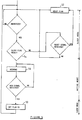
- FIG. 6 there is shown a typical flow diagram of the operation of a transponder 10.
- the diagram is self-explanatory and illustrates the step of setting flag 20 at block 50, after an acknowledgement signal 82 has been received from the reader 100.
- the transponder then enters the sleep mode as hereinbefore described.
- the transponder remains in this mode until the flag 20 is reset at 52.
- the flag When the flag has been reset, it enters the active mode at 54.
- the transponder In the aforementioned active mode, the transponder automatically responds with the response data (as shown at block 56) while being energized. When it enters the sleep mode, it no longer responds to the energizing signal, even if energized.
- the sensitivity of the reset signal detection circuitry 72 of the transponder 70 is arranged to be bigger than that of the circuitry 74 for processing the acknowledgement signals.
Landscapes
- Engineering & Computer Science (AREA)
- Physics & Mathematics (AREA)
- Toxicology (AREA)
- Artificial Intelligence (AREA)
- Computer Vision & Pattern Recognition (AREA)
- General Physics & Mathematics (AREA)
- Theoretical Computer Science (AREA)
- Health & Medical Sciences (AREA)
- Computer Networks & Wireless Communication (AREA)
- Electromagnetism (AREA)
- General Health & Medical Sciences (AREA)
- Radar Systems Or Details Thereof (AREA)
- Near-Field Transmission Systems (AREA)
Applications Claiming Priority (2)
| Application Number | Priority Date | Filing Date | Title |
|---|---|---|---|
| ZA9711244 | 1997-12-15 | ||
| ZA9711244 | 1997-12-15 |
Publications (2)
| Publication Number | Publication Date |
|---|---|
| EP0924635A2 true EP0924635A2 (fr) | 1999-06-23 |
| EP0924635A3 EP0924635A3 (fr) | 2001-01-10 |
Family
ID=25586774
Family Applications (1)
| Application Number | Title | Priority Date | Filing Date |
|---|---|---|---|
| EP98310249A Withdrawn EP0924635A3 (fr) | 1997-12-15 | 1998-12-14 | Système électronique d'identification avec un lecteur et une pluralité de transpondeurs |
Country Status (3)
| Country | Link |
|---|---|
| EP (1) | EP0924635A3 (fr) |
| JP (1) | JPH11266177A (fr) |
| CN (1) | CN1231457A (fr) |
Cited By (9)
| Publication number | Priority date | Publication date | Assignee | Title |
|---|---|---|---|---|
| EP1321889A3 (fr) * | 2001-12-20 | 2003-07-09 | Matsushita Electric Industrial Co., Ltd. | Unité de lecture/écriture de cartes à puce, procédé d'identification |
| WO2004066188A3 (fr) * | 2003-01-24 | 2004-11-11 | Comtrack Ab | Systeme et emetteur |
| WO2005078633A1 (fr) * | 2004-02-06 | 2005-08-25 | Zih Corp | Procede de selection de groupe d'etiquettes d'identification par radiofrequence (rfid) |
| FR2888969A1 (fr) * | 2005-07-22 | 2007-01-26 | Spacecode Sa | Etiquette electronique, procede de lecture et procede d'interrogation d'une telle etiquette electronique |
| WO2007150045A3 (fr) * | 2006-06-22 | 2008-04-10 | Sirit Technologies Inc | Système et procédé d'interrogation d'étiquettes radiofréquence |
| US8174365B2 (en) | 2005-09-27 | 2012-05-08 | Renesas Electronics Corporation | IC tag, method of controlling the IC tag, and IC tag system |
| US9323964B2 (en) | 2013-08-20 | 2016-04-26 | Cubic Corporation | Card detection and selection |
| US9729363B2 (en) | 2013-09-09 | 2017-08-08 | Crfs Limited | Frequency discriminator |
| US11057001B2 (en) | 2020-06-14 | 2021-07-06 | Intel Corporation | Apparatus, system, and method of distributing a reset signal to a plurality of PHY chains |
Families Citing this family (7)
| Publication number | Priority date | Publication date | Assignee | Title |
|---|---|---|---|---|
| US7590397B2 (en) | 2003-09-10 | 2009-09-15 | Sony Corporation | Signal processing apparatus and signal processing method, program, and recording medium |
| US7119664B2 (en) * | 2003-09-17 | 2006-10-10 | Id Solutions, Inc. | Deep sleep in an RFID tag |
| WO2008149422A1 (fr) | 2007-06-05 | 2008-12-11 | Fujitsu Limited | Dispositif de stockage d'informations sans contact actif pour stocker une valeur de détection par un capteur |
| WO2009001446A1 (fr) * | 2007-06-27 | 2008-12-31 | Fujitsu Limited | Système d'accès à des informations, dispositif de lecture et d'écriture sans contact, et dispositif mémoire d'informations non contact |
| JP4840674B2 (ja) * | 2009-03-23 | 2011-12-21 | ソニー株式会社 | 信号処理装置および信号処理方法、プログラム、並びに記録媒体 |
| CN111127712B (zh) * | 2019-12-26 | 2022-04-29 | 重庆集诚汽车电子有限责任公司 | 一种基于peps控制器的智能钥匙自动学习方法 |
| DE102021101180A1 (de) * | 2021-01-21 | 2022-07-21 | Sick Ag | Sicherheitssystem |
Family Cites Families (4)
| Publication number | Priority date | Publication date | Assignee | Title |
|---|---|---|---|---|
| US5640151A (en) * | 1990-06-15 | 1997-06-17 | Texas Instruments Incorporated | Communication system for communicating with tags |
| DK0467036T3 (da) * | 1990-06-15 | 1996-03-11 | Savi Techn Inc | Fremgangsmåde og apparatur til radioidentifikation og sporing |
| US5673037A (en) * | 1994-09-09 | 1997-09-30 | International Business Machines Corporation | System and method for radio frequency tag group select |
| JPH08123919A (ja) * | 1994-10-28 | 1996-05-17 | Mitsubishi Electric Corp | 非接触icカードシステムおよびその通信方法 |
-
1998
- 1998-12-14 EP EP98310249A patent/EP0924635A3/fr not_active Withdrawn
- 1998-12-15 JP JP10355601A patent/JPH11266177A/ja active Pending
- 1998-12-15 CN CN98127136.7A patent/CN1231457A/zh active Pending
Cited By (15)
| Publication number | Priority date | Publication date | Assignee | Title |
|---|---|---|---|---|
| US7011250B2 (en) | 2001-12-20 | 2006-03-14 | Matsushita Electric Industrial Co., Ltd. | IC card reader/writer, identification method and program |
| EP1321889A3 (fr) * | 2001-12-20 | 2003-07-09 | Matsushita Electric Industrial Co., Ltd. | Unité de lecture/écriture de cartes à puce, procédé d'identification |
| WO2004066188A3 (fr) * | 2003-01-24 | 2004-11-11 | Comtrack Ab | Systeme et emetteur |
| CN1934575B (zh) * | 2004-02-06 | 2011-06-08 | Zih公司 | 射频识别组选择方法 |
| WO2005078633A1 (fr) * | 2004-02-06 | 2005-08-25 | Zih Corp | Procede de selection de groupe d'etiquettes d'identification par radiofrequence (rfid) |
| US8981909B2 (en) | 2004-02-06 | 2015-03-17 | Zih Corp. | RFID group selection method |
| FR2888969A1 (fr) * | 2005-07-22 | 2007-01-26 | Spacecode Sa | Etiquette electronique, procede de lecture et procede d'interrogation d'une telle etiquette electronique |
| US8174365B2 (en) | 2005-09-27 | 2012-05-08 | Renesas Electronics Corporation | IC tag, method of controlling the IC tag, and IC tag system |
| US8330581B2 (en) | 2005-09-27 | 2012-12-11 | Renesas Electronics Corporation | IC tag, method of controlling the IC tag, and IC tag system |
| WO2007150045A3 (fr) * | 2006-06-22 | 2008-04-10 | Sirit Technologies Inc | Système et procédé d'interrogation d'étiquettes radiofréquence |
| US8228173B2 (en) | 2006-06-22 | 2012-07-24 | Sirit Inc. | Interrogating radio frequency tags |
| US9323964B2 (en) | 2013-08-20 | 2016-04-26 | Cubic Corporation | Card detection and selection |
| US9729363B2 (en) | 2013-09-09 | 2017-08-08 | Crfs Limited | Frequency discriminator |
| US11057001B2 (en) | 2020-06-14 | 2021-07-06 | Intel Corporation | Apparatus, system, and method of distributing a reset signal to a plurality of PHY chains |
| EP3923119A1 (fr) * | 2020-06-14 | 2021-12-15 | Intel Corporation | Appareil, système et procédé de distribution d'un signal de réinitialisation à une pluralité de chaînes phy |
Also Published As
| Publication number | Publication date |
|---|---|
| EP0924635A3 (fr) | 2001-01-10 |
| CN1231457A (zh) | 1999-10-13 |
| JPH11266177A (ja) | 1999-09-28 |
Similar Documents
| Publication | Publication Date | Title |
|---|---|---|
| EP0924635A2 (fr) | Système électronique d'identification avec un lecteur et une pluralité de transpondeurs | |
| US5036308A (en) | Identification system | |
| US5537105A (en) | Electronic identification system | |
| US6909366B1 (en) | Multi-dimensional electronic identification of articles | |
| EP1001366B1 (fr) | Système d'identification électronique | |
| US6091342A (en) | Transponder communication device for the contactless communication with at least one transponder, and transponder for the contactless communication with at least one transponder communication device | |
| US6995655B2 (en) | Method of simultaneously reading multiple radio frequency tags, RF tags, and RF reader | |
| US5548291A (en) | Read/write transponder arrangement and method of communication | |
| AU2003269958B2 (en) | Pulsed power method for increased read range for a radio frequency identification reader | |
| JPH0897755A (ja) | 高周波トランスポンダ装置 | |
| US6198381B1 (en) | Delayed reset mode model for electronic identification systems | |
| KR20060131773A (ko) | 디바이스들을 식별하는 방법 및 장치 | |
| JP4063758B2 (ja) | 超音波識別装置及び方法 | |
| US6097278A (en) | Transponder communication device for the contactless communication with a plurality of individually selectable transponders, and transponder for the contactless communication with at least one transponder communication device | |
| JPH08167090A (ja) | 移動体識別方法 | |
| JP3171310B2 (ja) | 移動体検出装置 | |
| KR101042389B1 (ko) | Rfid 시스템에서 인식 슬롯 스캔 과정을 이용한 태그 수집 방법 | |
| JPH08101999A (ja) | 移動体検出装置 | |
| JPH01280274A (ja) | 物体識別装置における応答器の応答方式 | |
| JPH10294684A (ja) | データ伝送装置 | |
| WO2003040998A1 (fr) | Procede et systeme destines a echantillonner de facon periodique plusieurs transpondeurs | |
| HK1073961B (en) | Pulsed power method for increased read range for a radio frequency identification reader |
Legal Events
| Date | Code | Title | Description |
|---|---|---|---|
| PUAI | Public reference made under article 153(3) epc to a published international application that has entered the european phase |
Free format text: ORIGINAL CODE: 0009012 |
|
| AK | Designated contracting states |
Kind code of ref document: A2 Designated state(s): AT BE CH DE ES FR GB IT LI NL |
|
| AX | Request for extension of the european patent |
Free format text: AL;LT;LV;MK;RO;SI |
|
| PUAL | Search report despatched |
Free format text: ORIGINAL CODE: 0009013 |
|
| AK | Designated contracting states |
Kind code of ref document: A3 Designated state(s): AT BE CH CY DE DK ES FI FR GB GR IE IT LI LU MC NL PT SE |
|
| AX | Request for extension of the european patent |
Free format text: AL;LT;LV;MK;RO;SI |
|
| RIC1 | Information provided on ipc code assigned before grant |
Free format text: 7G 06K 7/00 A, 7G 06K 7/10 B, 7G 06K 7/08 B, 7G 06K 19/07 B |
|
| 17P | Request for examination filed |
Effective date: 20010710 |
|
| AKX | Designation fees paid |
Free format text: AT BE CH DE ES FR GB IT LI NL |
|
| STAA | Information on the status of an ep patent application or granted ep patent |
Free format text: STATUS: THE APPLICATION HAS BEEN WITHDRAWN |
|
| 18W | Application withdrawn |
Effective date: 20030306 |