EP0924652A2 - Mélange de donnees d'images par couches - Google Patents
Mélange de donnees d'images par couches Download PDFInfo
- Publication number
- EP0924652A2 EP0924652A2 EP98310492A EP98310492A EP0924652A2 EP 0924652 A2 EP0924652 A2 EP 0924652A2 EP 98310492 A EP98310492 A EP 98310492A EP 98310492 A EP98310492 A EP 98310492A EP 0924652 A2 EP0924652 A2 EP 0924652A2
- Authority
- EP
- European Patent Office
- Prior art keywords
- layer
- blending
- data
- buffer
- layers
- Prior art date
- Legal status (The legal status is an assumption and is not a legal conclusion. Google has not performed a legal analysis and makes no representation as to the accuracy of the status listed.)
- Granted
Links
Images


Classifications
-
- G—PHYSICS
- G06—COMPUTING OR CALCULATING; COUNTING
- G06T—IMAGE DATA PROCESSING OR GENERATION, IN GENERAL
- G06T11/00—Two-dimensional [2D] image generation
- G06T11/60—Creating or editing images; Combining images with text
-
- G—PHYSICS
- G06—COMPUTING OR CALCULATING; COUNTING
- G06T—IMAGE DATA PROCESSING OR GENERATION, IN GENERAL
- G06T15/00—Three-dimensional [3D] image rendering
- G06T15/50—Lighting effects
- G06T15/503—Blending, e.g. for anti-aliasing
Definitions
- the present invention relates generally to methods and systems for blending computer generated graphics objects and more particularly to methods and apparatus for blending computer generated graphics objects using layers.
- a computer system can output data to a wide variety of output display devices.
- Output display devices such as laser printers, plotters, image setters and other printing devices produce an image or "visual representation" onto a sheet of paper, a piece of film or the like, while output display devices such as computer monitors develop visual representations on a computer screen.
- a pixel is a fundamental picture element of a visual representation generated by a display device
- a pixelmap is a data structure including information concerning a number of pixels of the representation.
- a printing device prints dots on a piece of paper corresponding to the information in a pixelmap.
- a computer monitor illuminates pixels based upon the information in a pixelmap.
- a "raster" output device creates a visual representation by displaying arrays of pixels arranged in rows and columns from the pixelmap. Most output devices, other than plotters, are raster output devices.
- a page description language is a high level language for describing objects to be displayed by an output device.
- the PostScript® language developed by Adobe Systems Incorporated of San Jose, California, is an example of a page description language.
- An image to be displayed may be represented and stored in a page description format as a page description language file which includes one or more objects.
- a page description language is device independent.
- a conventional printing device configured to process a page description language file interprets the objects within the file and renders the data into pixelmaps to be painted into a frame buffer.
- the frame buffer is large enough to store (at least in compressed form) any page that might be printed, and rendered pixelmaps are stored in this buffer.
- data stored in the frame buffer may transferred to a print engine or marking engine for printing.
- Transparency is a visual blending effect obtained when a background object (image, text, lines or filled regions) is partially obscured by a foreground object that is drawn over the background object.
- blending effects include a drop shadow effect, a screen effect, darker and lighter effects and overprinting effects.
- the invention features a method of blending graphics data that includes a plurality of objects.
- the method includes grouping the objects into two layers; drawing the objects associated with a first layer; drawing the objects associated with a second layer; and blending data drawn into the first and second layers.
- the drawing step includes rendering object data to generate a pixelmap.
- the drawing step includes computing a planar map representation of the objects.
- the method is implemented in a printing device. Objects are drawn opaquely into each layer. One of the first and second layers is drawn into a frame buffer. Data drawn into one of the first and second layers is drawn into a layer buffer, the layer buffer being partitioned into a plurality of tiles, each tile for receiving data associated with a particular portion of a page to be printed; the method includes compressing tiles of the layer buffer into which data is not currently being drawn.
- the layer buffer is partitioned into a plurality of bands.
- the step of blending includes blending drawn data from the first and second layer according to a predefined blending operation. The predefined blending operation is selected from the group of transparency, shadow, overprinting, darkening, lightening, screen effect and additive effect.
- the invention features a method of blending graphics data in an output display device.
- the method includes providing groupings of object data associated with an image to be displayed, each grouping defining a layer of the image; creating a layer stack associated with image, the layer stack defining a hierarchy for blending layers of the image; rendering object data associated with each layer; and blending rendered object data for the layers.
- the blending step is performed two layers at time, including selecting layers for blending by popping layers off the layer stack.
- the invention features a method of blending graphics data in an output display device.
- the method includes providing groupings of object data associated with an image to be displayed, each grouping defining a layer of the image; providing layer blending information defining a hierarchy for blending layers of the image; rendering object data associated with each layer; and blending rendered object data for the layers.
- the blending step is performed two layers at time including selecting layers for blending based on the layer blending information.
- the invention features a method of blending graphics data received by a printing device.
- the method includes receiving object data associated with a first layer of an image to be displayed; transforming the object data to an intermediate form representative of an underlying graphics object; storing the intermediate form data in a first buffer; receiving object data associated with a second layer of the image; transforming the object data to an intermediate form representative of an underlying graphics object; blending intermediate form data for the first and second layer to derive blended data; and printing the image.
- the invention features a method of blending graphics data received by a printing device to provide a blending effect for a foreground image with respect to a background image.
- the method includes receiving one or more foreground objects to be drawn into a foreground layer; drawing the foreground objects to generate foreground data; receiving one or more of background objects to be drawn into a background layer; drawing the background objects to generate background data; blending the foreground and background data to generate a composite image for printing.
- the invention features a method of blending graphics data received by a printing device.
- the method includes providing one or more objects associated with a first layer of an image to be printed; rendering the objects associated with the first layer; storing rendered object data associated with the first layer in a first buffer; providing one or more objects associated with a second layer of the image; rendering the objects associated with the second layer; storing rendered object data associated with the second layer in a second buffer; blending the rendered object data for the first and second layers; and printing the blended rendered object data.
- the invention features an apparatus for blending graphics data in a output display device.
- the apparatus includes an interpreter for receiving object data associated with two layers of an image to be displayed by the output display device and for receiving a layer operator for designating which objects belong to which layer; a drawing engine for drawing objects into a first and a second buffer, the first buffer for receiving data associated with a first layer and the second buffer for receiving data associated with a second layer; and a blend processor for blending data in the first and second buffers prior to display.
- One of the first and second buffers is a layer buffer, the layer buffer being partitioned into a plurality of bands, each band for receiving data associated with a particular portion of a page to be displayed; and the apparatus includes a compression engine for compressing bands of the layer buffer into which data is not currently being drawn.
- the drawing engine includes a render engine for generating pixel data from higher level object data, for receiving object data from the interpreter and for painting pixel data representative of the object data into one of the first and second buffers for all objects in a same layer.
- the apparatus includes a layer table for storing layer information including blending instructions to direct the output display device to perform a desired blend.
- the interpreter receives a layer operator indicating a transition between layers and, responsive to the layer operator, data is drawn into a new layer buffer.
- the invention features an apparatus for blending graphics data in a output display device.
- the apparatus includes a frame buffer for storing rendered object data associated with a plurality of objects to be placed in a background layer of an image; a layer buffer for storing rendered object data associated a plurality of objects to be placed in a foreground layer of an image; and a blend processor for blending the foreground and background layers.
- the layer buffer is dynamically allocatable and de-allocatable based in part upon receipt of a blending instruction with graphics objects associated with the image.
- the invention features a printer configured to receive a page description language description of a page to be printed.
- the printer includes a frame buffer for storing render data; a layer buffer for temporarily storing rendered data for a layer of an image to printed; a blending engine for blending rendered data stored in the frame buffer and layer buffer; and a print engine for printing blended data resulting in a blending of graphics data according to a user defined blending function.
- Blending effects may be implemented in printers that would otherwise not have sufficient memory to support conventional blending methods.
- a layering process is provided in a display device to allow for division of an image or portion of an image into one or more layers. Blending of objects associated with one or more layers of an image may thereafter be advantageously achieved.
- a layering process may be advantageously implemented in systems that manipulate graphics data in display list format or in other formats.
- Layers may be blended in any order and combination to achieve a desired visual effect in the output image. Layers may be nested in multiple layers and resolved according to user preferences in the formulation of an output image which is delivered to a print or display engine.
- a simple stack hierarchy may be used to define relationships between layers and the ordering for blending of the layers in the formulation of blended graphics objects.
- Layer buffers may be allocated and deallocated dynamically as required to create a desired visual effect. Any number of combinations of differing sized layer buffers may be active at any given time.
- Blending effects may be implemented that otherwise would be impossible in a conventional output display device.
- inventive teachings disclosed allow for the elimination of undesirable artifacts and other cumulative effects in blending multiple objects.
- the present invention may be embodied in any output display device that receives page description data and produces an output image from the data, for example on a computer monitor or a piece of paper.
- the invention has particular applicability to printing devices and will be described in terms of an embodiment in such a device, which will be referred to simply as a printer.
- Printers include plotters, image setters, digital presses, laser printers, dot matrix printers, ink jet printers and the like.
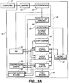
- a printer 16 receives input data, from a computer 12, for example, and turns the input data into marks on a piece of paper by sending signals to a print engine 34.
- the printer 16 is configured to receive page description language input data and process it as will be described later.
- One suitable page description language is the PostScript language.
- the PostScript language is described in Adobe Systems Incorporated, Adobe Postscript® Language Reference Manual, Addison-Wesley (2d ed., ⁇ 1990).
- Another suitable page description language is the PCL language available from the Hewlett-Packard Company of Palo Alto, California.
- a page description language file sent to a printer specifies objects to be displayed and related information.
- a PostScript object can, for example, include a pixelmap defining a pattern of pixels to be displayed, or the object may reference an outline curve defining a shape to be marked.
- the object may also include other information such as font and size for character objects and blend information as will be described in greater detail below.
- the printer 16 includes a buffer 24, a digital data processor, random access memory 28 and print engine 34. It also typically includes read-only memory, I/O interfaces, and data transfer paths and busses, none of which are shown.
- the digital data processor may be a general or special purpose microprocessor operating under control of computer program instructions executed from a memory.
- the processor may include a number of special purpose sub-processors, each sub-processor for executing particular portions of the computer program instructions.
- the processor includes an interpreter 50, a raster image processor (RIP) 52 and blend processor 58.
- RIP raster image processor
- Each sub-processor may be a separate circuit able to operate substantially in parallel with the other sub-processors.
- Some or all of the sub-processors may be implemented as computer program processes (software) tangibly stored in a memory that perform their respective functions when executed. These may share an instruction processor, such as a general purpose integrated circuit microprocessor, or each sub-processor may have its own processor for executing instructions. Alternatively, some or all of the sub-processors may be implemented in an ASIC (application specific integrated circuit)
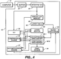
- RAM 28 is a random access memory used by the processor and sub-processors 50, 52 and 58.
- RAM 28 may include display list memory 60, a frame buffer 62, any number of layer buffers 63 and a layer table 65 including a current buffer pointer 66.
- RAM 28 may be partitioned into one or more regions or embodied in one or more separate memory devices.
- layer buffers 63 are dynamically allocated and may be used for storing pixel data associated with one or more layers of an output image.
- a layer buffer typically is sized smaller than a frame buffer and may be dynamically sized based on the data objects required to be drawn into a given layer.
- Each layer buffer 63 may be structured similar to a frame buffer and may be divided into one or more bands.
- the structure of the layer buffers may be independent of the frame buffer structure and may be optimized based on a specific implementation.
- a particular printing device may include a banded frame buffer, that is, a frame buffer that is divided into a plurality of bands, into which object data may be painted covering a predefined portion of a page to be printed.
- a user may desire to blend two or more layers of graphics objects within a single band of the frame buffer.
- the frame buffer is a band device; however, the implementation of the layer buffers needed to provide a layer blend within a single band does not require the layer buffers to be similarly structured.
- Frame buffer 62 may be a deep or shallow frame buffer.
- a shallow frame buffer is configured to store render data typically having a bit depth of one (1) bit per pixel.
- a deep frame buffer is configured to store render data typically having a bit depth of greater than one (1) bit per pixel.
- Manipulation of shallow buffer data in order to achieve blending is described in detail in "Dehalftoning of Digital Images" by Steve Carlsen cited above.
- a deep frame buffer example will be described herein.
- Frame buffer 62 may be used to store objects rendered into a background layer of an output image, while layer buffers 63 may be used to store foreground rendered data prior to blending with the background layer.
- frame buffer 62 may be used to store resultant data derived from a blend of one or more layers and the background.
- Layer table 65 may be used to store layer data and may memory address information indicating where in memory data associated with a given layer is stored, blending instructions and a current buffer pointer.
- Objects received by interpreter 50 may be interpreted into display list data for storage in display list memory 60.
- graphics data objects may be immediately painted by RIP 52 as pixelmaps into frame buffer 62 or a layer buffer 63.
- RIP 52 may paint objects opaquely into frame buffer 62 or layer buffers 63.
- blending of individual objects at the layer level may be achieved as is described in "Blending Graphics Objects in a Frame Buffer" by Stephen Carlsen, Lars Borg and Stephen Schiller as cited above.
- RAM 28 may be embodied in one or more memory chips. If display list memory 60 and the frame buffer 62 are consolidated into a single memory (a consolidated memory), then the memory may be partitioned or otherwise mapped to reflect the boundaries of the various memory sub-components.
- printer components that have been described can be packaged in a single product; alternatively, some can be included in computer 12 or otherwise housed separately.
- Printer 16 receives object data and blend operators from computer 12 (202).
- Printer 16 may be configured to a default mode by setting a current buffer pointer to point to frame buffer 62 (203). In the default mode, interpreter 50 directs the output of RIP 52 so that data objects received may be painted directly into frame buffer 62 (the "default layer")
- RIP 52 may paint objects received directly into an designated layer buffer.
- Step 204 results in the painting of object data into a "current buffer", that is, either a layer buffer or the frame buffer depending on the location indicated by the current buffer pointer.
- the current buffer pointer may be maintained by interpreter 50 and modified upon receipt of a tag (herein after a "layer operator") that precedes or accompanies a particular graphics object.
- the frame buffer may be used to store background data associated with a background layer and may be written to as the current buffer whenever background data is provided from computer 12.
- a foreground data object including a layer operator may be used to update the current buffer pointer to point to a layer buffer thereby enabling RIP 52 to directly paint foreground render data into the appropriate foreground layer location in memory.
- interpreter 50 Upon receipt of a layer operator (212), interpreter 50 processes the layer operator by allocating a portion of memory (a layer buffer) to store layer data and directs the painting of objects associated with the designated layer from the RIP to the layer buffer by setting the current buffer pointer (214).
- a layer buffer a portion of memory
- the layer buffer may be blended by blend processor with another layer according to blending instructions received from computer 12 (209).
- the blend results in a single layer (two layers blended into one).
- the blending may result in the deallocation of memory associated with one of the original layers and may result in an update to the current buffer pointer. The process continues until the end of the page is reached (206).
- blending processor checks to determine if any outstanding layers remain to be blended (208). If no layers remain to be blended, the page may be printed by passing data from the frame buffer 62 directly to the print engine 34 (210). If any layers remain to be processed, then the layers may be blended by blending processor 58 (216). Alternatively, outstanding layer buffers may be held over for a next page, discarded, or otherwise processed by blending processor 58.
- resultant data stored in frame buffer 62 may be transferred to print engine 34 for printing (210). Thereafter the process may end (220).
- the objects associated with one layer may be received sequentially prior to the receipt of any objects associated with a second layer as is described above.
- object data may be received in random order.
- Layers may be blended according to blending information provided from computer 12.
- the blending information may define both the timing and algorithm to be used in the blending operation.
- Various blending algorithms may be invoked by blending processor 58 to blend two layers. Blending processor 58 combines the pixel values at each location in the layers according to an appropriate blending formula.
- Blending processor 58 may support one or more of the blending formulas.
- a user-defined selection for the method to be used may be provided by computer 12 in the form of blending instructions as part of a layer operator.
- the instructions may be stored in layer table 65 for retrieval at the time for blending.
- printer 16 may include compression 55 and decompression engines 57.
- Compression engine 55 may be used to compress data stored in a buffer that is not the current buffer.
- decompression engine 57 may be used to decompress compressed data stored in a buffer prior to the addition of more objects or the blending of data with data from another buffer.
- the process 200 for blending layers is modified to include a step of determining if graphics objects are to be rendered into a new buffer (e.g., the frame buffer or a layer buffer) by determining if a new current buffer is indicated (213a). Objects received from computer 12 are required to be written to a new buffer when the current buffer being painted into by the RIP is not the same buffer into which subsequent objects are to be rendered. If no new current buffer is set, then the process continues at step 214.
- a new buffer e.g., the frame buffer or a layer buffer
- the contents of the current buffer may be compressed (213b). Thereafter, the contents of the new current buffer may be decompressed as appropriate prior to painting more object data into the new current buffer (213c). Decompression may also be added if a layer operation requires the blending of layers or the writing of new data to a previously compressed buffer. In addition, a decompression step (215) may be required to be added prior to the blending step 216 to decompress data stored in at least one layer buffer 63.
- frame buffer 16 may be divided to include an uncompressed band buffer 62-1 and compressed band buffer 62-2.
- Uncompressed band buffer 62-1 may be sized to hold one or more bands of uncompressed render data.
- Compressed band buffer 62-2 may be sized to store a compressed form of the render data.
- Each layer buffer 63 may be similarly configured to include an uncompressed and a compressed portion (not shown). The uncompressed portion may be used to paint data directly from RIP 52, while the compressed portion may be used to store one or more compressed bands of previously rendered data.
- the frame buffer and layer buffers may share an uncompressed band buffer into which all rendered data is written by RIP 52.
- Interpreter 50 receives object data from computer 12 and stores the object data in display lists in display list memory 60.
- RIP 52 may render the object data stored in the display list for the given band painting directly into a band of the uncompressed band buffer 62-1.
- compression engine 55 may be invoked to compress the data for the band and store the resultant compressed data in the compressed band buffer 62-2 or in the compressed portion of a layer buffer.
- a cycling operation may be invoked.
- a band of previously compressed data may be decompressed and stored in the uncompressed band buffer 62-1.
- Objects may then be rendered into the band by RIP 52.
- the band may again be compressed and stored in the compressed band buffer 62-2 or in the compressed portion of a layer buffer.
- the process for blending layers may require decompressing compressed bands of a given layer prior to blending with a corresponding band associated with another layer.
- the description above is directed to printing a two layer blend, as might be used in blending a foreground layer, stored in a layer buffer, with a background layer, stored in the frame buffer, to achieve a desired visual effect. More complex visual effects may be achieved by including more than two layers. In order to achieve such results, a hierarchy for blending is required to be provided from the host computer or may be inferred by the display device.
- printer 16 may include a layer stack embodied in layer table 65. Stacking of layers may be inferred from the order of layer data is created or received.
- computer 12 may provide a layer operator that designates the transition between layers and blending instructions for blending the new layer with its parent layer in the layer stack. A log of such layer operators may be maintained in layer table 65 by interpreter 50. Each entry in the layer table may be associated with a single layer. At the time for blending (after all graphics objects have been processed for a given page), layers may be blended in reverse order received, two layers at a time, by the blending processor according to the blending instructions.
- Blending instructions may be included with the layer operator that define the order in which the layers may be blended (e.g., layer one with layer three, the composite of which is blended with layer two) .
- more complex blends may be achievable by nesting layers in the hierarchy and allowing for the control over when layers are to be blended, as opposed to at the end of processing of all graphics objects associated with a given page.
- a page description language structure for blending layers may include a layer stack architecture and at least three types of layer operators.
- the layer operators may be provided by computer 12 to direct printer 16 to perform a desired blend.
- a create layer operator may be used to designate a new layer.
- interpreter 50 creates an new entry in layer table 65.
- a create layer operator may be required for each layer in an graphics data blend.
- layers are "pushed" onto a stack embodied in the layer table 65. Parent and sibling relationships in the hierarchical stack can be defined for each layer created.
- a current layer operator may be used to designate that the objects following (or accompanying) the operator belong to a certain layer.
- the interpreter may direct the transfer of rendered data from RIP 52 to a layer buffer.
- the current layer operator operates much the same as the layer operator described in conjunction with FIG. 2. The processing of a current layer operator has no effect on the contents of the hierarchical stack.
- a render layer operator may be used to invoke the blending of layers on the stack.
- the render layer operator may take the form of a pop instruction.
- the blend processor may pop a layer from the stack (a child layer), blend the layer with its parent layer in the hierarchical stack, and store the result in the parent layer buffer.
- the pop operation results in the removal (deallocation) of an element from the layer table (the child layer) and a modification to the parent layer as a result of the blending operation.
- the process includes initializing the current buffer pointer to point to the frame buffer (301). Objects and layer operators are received from a computer 12 to be processed (302) If object data is received (303), the graphics objects are processed by RIP 52 and painted directly into the current buffer (304).
- Each entry in the layer table may include a layer identifier, a buffer identifier, and a compression flag.
- a buffer identifier identifies the location in RAM 28 where data associated with the layer is stored (either a layer buffer or the frame buffer).
- the compression flag indicates whether or not the layer data is in a compressed form and thus requires decompression prior to retrieval, blending or other processing.
- the current buffer pointer is updated (308) and the process continues at step 304.
- a render layer operator is received (322) then two layers on the stack are blended by the blend processor 58 (324).
- the layer operator may define which two layers are to be blended or a default selection may be made to blend the last two layers added to the stack, the last layer and the current layer (as indicated by the current buffer pointer) or other another pair of layers.
- the layer table is updated to remove one of the layers from the stack (326), and the resultant layer data derived from the blending operation is returned to be stored in the other layer buffer (328).
- blending processor 58 blends the layers according to the stack order two layers at a time until all the layers are blended (316) and then passes the resultant data to the frame buffer (318).
- the blend processor processes layers from the stack by combining the last layer created with its parent on the stack (the previous layer received in time).
- the resultant image is then combined with the next layer in the stack hierarchy until all of the layers have been blended, the result of which may be blended with the contents of the frame buffer.
- Other default hierarchies may be employed. For example, all layers that are children of a parent layer in the hierarchy may be blended before blending a parent layer with a "sibling" layer within the same hierarchical level.
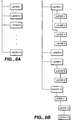
- the render layer and create layer operators allow for the creation of complex blending hierarchies.
- the create layer operator allows for the ordering of layers in a stack. In the example shown, when all the objects associated with a given page have been processed, a blend of the layers in the stack in reverse order received results in a single level hierarchy.
- FIG. 6b a more complex hierarchy may be realized by using the render layer operator in conjunction with the create operator. Nesting of layers in a parent/child hierarchy is achievable by sequencing the creation of layers along with blending of layers prior to the final blend time for the given page. These intermediate blends allow greater freedom to produce desired visual effects.
- a single layer may be desired to be blended into a plurality of other layers.
- One method for achieving this in printer 16 is to blend layers (e.g., a parent and a child layer) and draw the result of the blend back into one of the two layers (the parent layer) without affecting the contents of the second layer (the child layer).
- Copy buffer 67 may be used to store a copy of the data in the frame buffer so that the same layer may be blended with multiple layers in a hierarchy.
- the copy buffer may advantageously be used in conjunction with a render layer operator to achieve a desired visual effect.
- blending of graphics data may be ideally performed prior to the conversion of object data into pixel data by RIP 52.
- One or more layers of planar maps may be computed and stored in a display device to facilitate blending operations and the creation of complex visual effects.
- Each layer of memory may be used to store one or more planar maps representative of a grouping of one or more graphics objects to be combined.
- Planar maps may be combined to derive a composite map representative of the blending of the two planar map representations.
- a separate portion of memory must be allocated to store the resultant planar map (an existing planar map cannot be simply drawn into as is the case when operating on a pixel by pixel blend when using a frame buffer).
- Other blending methodologies may be utilized in addition to blending at the pixel level or the planar map level as described above. No matter the form or timing of the blend, the use of layers provides a flexible hierarchy for blending objects and may be realized by practicing the teachings of the present invention.
Landscapes
- Engineering & Computer Science (AREA)
- Physics & Mathematics (AREA)
- General Physics & Mathematics (AREA)
- Theoretical Computer Science (AREA)
- Computer Graphics (AREA)
- Record Information Processing For Printing (AREA)
- Editing Of Facsimile Originals (AREA)
- Processing Or Creating Images (AREA)
- Image Processing (AREA)
Applications Claiming Priority (2)
| Application Number | Priority Date | Filing Date | Title |
|---|---|---|---|
| US995592 | 1997-12-22 | ||
| US08/995,592 US6466210B1 (en) | 1997-12-22 | 1997-12-22 | Blending image data using layers |
Publications (3)
| Publication Number | Publication Date |
|---|---|
| EP0924652A2 true EP0924652A2 (fr) | 1999-06-23 |
| EP0924652A3 EP0924652A3 (fr) | 2001-06-13 |
| EP0924652B1 EP0924652B1 (fr) | 2012-01-18 |
Family
ID=25541978
Family Applications (1)
| Application Number | Title | Priority Date | Filing Date |
|---|---|---|---|
| EP98310492A Expired - Lifetime EP0924652B1 (fr) | 1997-12-22 | 1998-12-21 | Mélange de données d'images par couches |
Country Status (4)
| Country | Link |
|---|---|
| US (1) | US6466210B1 (fr) |
| EP (1) | EP0924652B1 (fr) |
| JP (1) | JP4883825B2 (fr) |
| CA (1) | CA2256891A1 (fr) |
Cited By (5)
| Publication number | Priority date | Publication date | Assignee | Title |
|---|---|---|---|---|
| EP1058211A1 (fr) * | 1999-05-28 | 2000-12-06 | Agfa Corporation | Méthode et appareil pour modifier des données en trame |
| WO2004040514A1 (fr) * | 2002-10-30 | 2004-05-13 | Canon Kabushiki Kaisha | Procede pour enlever la couleur de fond dans une image composite de porter et duff |
| US7088375B1 (en) | 2000-04-27 | 2006-08-08 | Adobe Systems Incorporated | Grouping layers in composited image manipulation |
| WO2008137957A1 (fr) * | 2007-05-07 | 2008-11-13 | Qualcomm Incorporated | Superpositions d'éléments graphiques après restitution |
| EP3211592A4 (fr) * | 2014-10-22 | 2017-08-30 | Huawei Technologies Co., Ltd. | Procédé de synthèse d'image, puce d'imagerie et dispositif d'image |
Families Citing this family (72)
| Publication number | Priority date | Publication date | Assignee | Title |
|---|---|---|---|---|
| US6856421B1 (en) * | 1997-09-30 | 2005-02-15 | Hewlett-Packard Indigo B.V. | Page composition system |
| US6636222B1 (en) | 1999-11-09 | 2003-10-21 | Broadcom Corporation | Video and graphics system with an MPEG video decoder for concurrent multi-row decoding |
| US6738072B1 (en) | 1998-11-09 | 2004-05-18 | Broadcom Corporation | Graphics display system with anti-flutter filtering and vertical scaling feature |
| US6853385B1 (en) | 1999-11-09 | 2005-02-08 | Broadcom Corporation | Video, audio and graphics decode, composite and display system |
| US7446774B1 (en) | 1998-11-09 | 2008-11-04 | Broadcom Corporation | Video and graphics system with an integrated system bridge controller |
| US6798420B1 (en) | 1998-11-09 | 2004-09-28 | Broadcom Corporation | Video and graphics system with a single-port RAM |
| US6661422B1 (en) * | 1998-11-09 | 2003-12-09 | Broadcom Corporation | Video and graphics system with MPEG specific data transfer commands |
| US7982740B2 (en) | 1998-11-09 | 2011-07-19 | Broadcom Corporation | Low resolution graphics mode support using window descriptors |
| US6768774B1 (en) | 1998-11-09 | 2004-07-27 | Broadcom Corporation | Video and graphics system with video scaling |
| US6573905B1 (en) | 1999-11-09 | 2003-06-03 | Broadcom Corporation | Video and graphics system with parallel processing of graphics windows |
| DE60033249D1 (de) * | 1999-09-02 | 2007-03-22 | Canon Kk | Progressive Anzeige von Zielobjekten |
| US6975324B1 (en) | 1999-11-09 | 2005-12-13 | Broadcom Corporation | Video and graphics system with a video transport processor |
| KR100354824B1 (ko) * | 1999-11-22 | 2002-11-27 | 신영길 | 시간 일관성을 이용한 실시간 렌더링 방법 및 렌더링 장치 |
| US6891550B1 (en) * | 2000-03-10 | 2005-05-10 | Paul Anthony John Nolan | Image manipulation software |
| US6831652B1 (en) * | 2000-03-24 | 2004-12-14 | Ati International, Srl | Method and system for storing graphics data |
| US6791556B1 (en) * | 2000-04-05 | 2004-09-14 | Avid Technology, Inc. | Multiframe rendering of video data on a general purpose computer |
| US20030002729A1 (en) * | 2001-06-14 | 2003-01-02 | Wittenbrink Craig M. | System for processing overlapping data |
| US6989840B1 (en) * | 2001-08-31 | 2006-01-24 | Nvidia Corporation | Order-independent transparency rendering system and method |
| US6809745B1 (en) * | 2001-10-01 | 2004-10-26 | Adobe Systems Incorporated | Compositing two-dimensional and 3-dimensional images |
| US20040083430A1 (en) * | 2002-10-29 | 2004-04-29 | Boonen Paul J. J. | Method and apparatus to process portable document format data containing transparency |
| US8036475B2 (en) * | 2002-12-13 | 2011-10-11 | Ricoh Co., Ltd. | Compression for segmented images and other types of sideband information |
| US7711834B2 (en) * | 2002-12-13 | 2010-05-04 | Ricoh Co., Ltd. | Network access to partial document images |
| US8769395B2 (en) * | 2002-12-13 | 2014-07-01 | Ricoh Co., Ltd. | Layout objects as image layers |
| US6879328B2 (en) * | 2003-03-03 | 2005-04-12 | Sun Microsystems, Inc. | Support of multi-layer transparency |
| US8063916B2 (en) | 2003-10-22 | 2011-11-22 | Broadcom Corporation | Graphics layer reduction for video composition |
| US8144360B2 (en) * | 2003-12-04 | 2012-03-27 | Xerox Corporation | System and method for processing portions of documents using variable data |
| US7265762B2 (en) * | 2003-12-17 | 2007-09-04 | Quid Novi, S.A., Inc. | Method and apparatus for representing data using layered objects |
| DE602004010777T2 (de) * | 2004-02-18 | 2008-12-04 | Harman Becker Automotive Systems Gmbh | Alphamischung auf Basis einer Nachschlagtabelle |
| US20050213119A1 (en) * | 2004-03-26 | 2005-09-29 | Lexmark International, Inc. | Processing print jobs according to size of to-be-printed objects and bands containing same |
| US20050213117A1 (en) * | 2004-03-26 | 2005-09-29 | Lexmark International, Inc. | Processing print jobs according to hard or easy processing zones |
| US7385729B2 (en) * | 2004-03-26 | 2008-06-10 | Lexmark International, Inc. | Optimization techniques during processing of print jobs |
| US7835030B2 (en) * | 2004-03-26 | 2010-11-16 | Lexmark International, Inc. | Processing print jobs |
| US7859716B2 (en) | 2004-03-26 | 2010-12-28 | Lexmark International, Inc. | Optimizing to-be-printed objects during print job processing |
| US20050213142A1 (en) * | 2004-03-26 | 2005-09-29 | Clark Raymond E | Optimization techniques during processing of print jobs |
| US7817302B2 (en) * | 2004-03-26 | 2010-10-19 | Lexmark International, Inc. | Optimizing raster operation functions during print job processing |
| US7684076B2 (en) * | 2004-07-23 | 2010-03-23 | Kabushiki Kaisha Toshiba | Method and apparatus for raster image processing |
| US7672521B2 (en) * | 2004-08-30 | 2010-03-02 | Hewlett-Packard Development Company, L.P. | System and method for improved page composition |
| US12051391B2 (en) | 2005-04-12 | 2024-07-30 | Douglas G. Richardson | Embedding animation in electronic mail, text messages and websites |
| US11232768B2 (en) | 2005-04-12 | 2022-01-25 | Douglas G. Richardson | Embedding animation in electronic mail, text messages and websites |
| US7629977B1 (en) | 2005-04-12 | 2009-12-08 | Richardson Douglas G | Embedding animation in electronic mail and websites |
| US8487939B2 (en) | 2005-04-12 | 2013-07-16 | Emailfilm Technology, Inc. | Embedding animation in electronic mail, text messages and websites |
| US7463261B1 (en) | 2005-04-29 | 2008-12-09 | Adobe Systems Incorporated | Three-dimensional image compositing on a GPU utilizing multiple transformations |
| US7499051B1 (en) | 2005-04-29 | 2009-03-03 | Adobe Systems Incorporated | GPU assisted 3D compositing |
| EP1729256B1 (fr) * | 2005-05-30 | 2018-03-07 | Harman Becker Automotive Systems GmbH | Processeur d'images |
| US20070037625A1 (en) * | 2005-06-28 | 2007-02-15 | Samsung Electronics Co., Ltd. | Multiplayer video gaming system and method |
| US7965902B1 (en) | 2006-05-19 | 2011-06-21 | Google Inc. | Large-scale image processing using mass parallelization techniques |
| US8762493B1 (en) | 2006-06-22 | 2014-06-24 | Google Inc. | Hierarchical spatial data structure and 3D index data versioning for generating packet data |
| CA2653908A1 (fr) * | 2006-06-29 | 2008-01-03 | Aftercad Software Inc. | Procede et systeme pour afficher et communiquer des informations de fichiers graphiques complexes |
| JP4169053B2 (ja) * | 2006-07-05 | 2008-10-22 | ブラザー工業株式会社 | 画像処理装置及び画像処理方法 |
| US7973797B2 (en) * | 2006-10-19 | 2011-07-05 | Qualcomm Incorporated | Programmable blending in a graphics processing unit |
| US7889205B1 (en) * | 2006-10-24 | 2011-02-15 | Adobe Systems Incorporated | Frame buffer based transparency group computation on a GPU without context switching |
| US20080294973A1 (en) * | 2007-05-21 | 2008-11-27 | Mohammad Suleiman | System and method for generating documents from multiple image overlays |
| US7928992B2 (en) * | 2007-05-30 | 2011-04-19 | Kabushiki Kaisha Toshiba | System and method for transparent object rendering |
| US8035641B1 (en) | 2007-11-28 | 2011-10-11 | Adobe Systems Incorporated | Fast depth of field simulation |
| US8405657B2 (en) * | 2008-09-09 | 2013-03-26 | Autodesk, Inc. | Animatable graphics lighting analysis |
| US9495796B2 (en) * | 2008-09-09 | 2016-11-15 | Autodesk, Inc. | Animatable graphics lighting analysis reporting |
| US20130342561A1 (en) * | 2010-07-19 | 2013-12-26 | Business Intelligence Solutions Safe B.V. | Data visualization rendering system and method |
| US9218680B2 (en) * | 2010-09-01 | 2015-12-22 | K-Nfb Reading Technology, Inc. | Systems and methods for rendering graphical content and glyphs |
| US8467601B2 (en) * | 2010-09-15 | 2013-06-18 | Kyran Daisy | Systems, methods, and media for creating multiple layers from an image |
| US9472018B2 (en) * | 2011-05-19 | 2016-10-18 | Arm Limited | Graphics processing systems |
| US9183609B2 (en) * | 2012-12-20 | 2015-11-10 | Nvidia Corporation | Programmable blending in multi-threaded processing units |
| AU2013211451A1 (en) | 2013-07-30 | 2015-02-19 | Canon Kabushiki Kaisha | Method of processing graphics with limited memory |
| KR20150033162A (ko) * | 2013-09-23 | 2015-04-01 | 삼성전자주식회사 | 컴포지터, 이를 포함하는 시스템온칩 및 이의 구동 방법 |
| JP6341732B2 (ja) * | 2014-04-08 | 2018-06-13 | キヤノン株式会社 | 印刷装置、印刷方法、及びプログラム |
| US10157439B2 (en) * | 2015-07-20 | 2018-12-18 | Qualcomm Incorporated | Systems and methods for selecting an image transform |
| US10319126B2 (en) * | 2016-08-16 | 2019-06-11 | Microsoft Technology Licensing, Llc | Ribbon to quick access toolbar icon conversion |
| CN109542382B (zh) * | 2017-12-26 | 2020-07-28 | 掌阅科技股份有限公司 | 手写输入内容的显示方法、电子设备及计算机存储介质 |
| KR102550124B1 (ko) * | 2018-06-22 | 2023-07-03 | (주)유주얼미디어 | 웹툰 배경을 위한 멀티패스 레이어 타입 카툰 쉐이더 방법 |
| US10748235B2 (en) * | 2018-08-08 | 2020-08-18 | Qualcomm Incorporated | Method and system for dim layer power optimization in display processing |
| US11373626B2 (en) | 2020-08-19 | 2022-06-28 | Konica Minolta Business Solutions U.S.A., Inc. | Ordering uncertainty representation using transparency blending |
| KR102766426B1 (ko) | 2020-08-31 | 2025-02-12 | 삼성전자주식회사 | 고해상도 디스플레이를 위한 영상 처리 장치, 영상 처리 방법 및 이를 포함하는 어플리케이션 프로세서 |
| JP2023173408A (ja) * | 2022-05-26 | 2023-12-07 | セイコーエプソン株式会社 | 情報処理装置、情報処理方法、プログラム |
Family Cites Families (14)
| Publication number | Priority date | Publication date | Assignee | Title |
|---|---|---|---|---|
| US5329616A (en) * | 1990-08-16 | 1994-07-12 | Canon Kabushiki Kaisha | Compressed image stores for high resolution computer graphics |
| JP2618101B2 (ja) | 1991-01-30 | 1997-06-11 | 大日本スクリーン製造株式会社 | 画像のレイアウト処理方法 |
| US5542052A (en) * | 1991-03-04 | 1996-07-30 | Adobe Systems Incorporated | Applying traps to a printed page specified in a page description language format |
| EP0568361B1 (fr) | 1992-04-29 | 1998-10-14 | Canon Kabushiki Kaisha | Dispositif pour la génération et mélange de couleurs |
| US5425137A (en) * | 1993-01-26 | 1995-06-13 | Us Jvc Corporation | System and method for processing images using computer-implemented software objects representing lenses |
| AUPM704194A0 (en) * | 1994-07-25 | 1994-08-18 | Canon Information Systems Research Australia Pty Ltd | Efficient methods for the evaluation of a graphical programming language |
| AUPM822394A0 (en) | 1994-09-16 | 1994-10-13 | Canon Inc. | Object based rendering system |
| US5737455A (en) * | 1994-12-12 | 1998-04-07 | Xerox Corporation | Antialiasing with grey masking techniques |
| US5600768A (en) | 1995-06-06 | 1997-02-04 | Apple Computer, Inc. | Image generation with dynamically consolidated list of image data |
| US5864342A (en) * | 1995-08-04 | 1999-01-26 | Microsoft Corporation | Method and system for rendering graphical objects to image chunks |
| US6016150A (en) * | 1995-08-04 | 2000-01-18 | Microsoft Corporation | Sprite compositor and method for performing lighting and shading operations using a compositor to combine factored image layers |
| US6064393A (en) * | 1995-08-04 | 2000-05-16 | Microsoft Corporation | Method for measuring the fidelity of warped image layer approximations in a real-time graphics rendering pipeline |
| JP3077581B2 (ja) * | 1996-01-19 | 2000-08-14 | 富士ゼロックス株式会社 | カラー印刷装置 |
| US6049339A (en) * | 1997-12-22 | 2000-04-11 | Adobe Systems Incorporated | Blending with planar maps |
-
1997
- 1997-12-22 US US08/995,592 patent/US6466210B1/en not_active Expired - Lifetime
-
1998
- 1998-12-21 CA CA002256891A patent/CA2256891A1/fr not_active Abandoned
- 1998-12-21 EP EP98310492A patent/EP0924652B1/fr not_active Expired - Lifetime
- 1998-12-22 JP JP36411598A patent/JP4883825B2/ja not_active Expired - Fee Related
Cited By (9)
| Publication number | Priority date | Publication date | Assignee | Title |
|---|---|---|---|---|
| EP1058211A1 (fr) * | 1999-05-28 | 2000-12-06 | Agfa Corporation | Méthode et appareil pour modifier des données en trame |
| US7088375B1 (en) | 2000-04-27 | 2006-08-08 | Adobe Systems Incorporated | Grouping layers in composited image manipulation |
| US7567260B2 (en) | 2000-04-27 | 2009-07-28 | Adobe Systems Incorporated | Grouping layers in composited image manipulation |
| WO2004040514A1 (fr) * | 2002-10-30 | 2004-05-13 | Canon Kabushiki Kaisha | Procede pour enlever la couleur de fond dans une image composite de porter et duff |
| US7864197B2 (en) | 2002-10-30 | 2011-01-04 | Canon Kabushiki Kaisha | Method of background colour removal for porter and duff compositing |
| WO2008137957A1 (fr) * | 2007-05-07 | 2008-11-13 | Qualcomm Incorporated | Superpositions d'éléments graphiques après restitution |
| EP3211592A4 (fr) * | 2014-10-22 | 2017-08-30 | Huawei Technologies Co., Ltd. | Procédé de synthèse d'image, puce d'imagerie et dispositif d'image |
| US10489948B2 (en) | 2014-10-22 | 2019-11-26 | Huawei Technologies Co., Ltd. | Image synthesis method, image chip, and image device |
| US10832462B2 (en) | 2014-10-22 | 2020-11-10 | Huawei Technologies Co., Ltd. | Image synthesis method, image chip, and image device |
Also Published As
| Publication number | Publication date |
|---|---|
| US6466210B1 (en) | 2002-10-15 |
| JPH11316831A (ja) | 1999-11-16 |
| EP0924652A3 (fr) | 2001-06-13 |
| EP0924652B1 (fr) | 2012-01-18 |
| JP4883825B2 (ja) | 2012-02-22 |
| CA2256891A1 (fr) | 1999-06-22 |
Similar Documents
| Publication | Publication Date | Title |
|---|---|---|
| US6466210B1 (en) | Blending image data using layers | |
| US6313847B1 (en) | Blending graphics objects in a frame buffer | |
| US6046818A (en) | Imposition in a raster image processor | |
| US6020897A (en) | Dehalftoning of digital images | |
| US5796930A (en) | System architecture for processing and transporting page-map or bit-map data to a raster print engine | |
| JP3166977B2 (ja) | フルカラーコンピユータグラフイツクスのパイプライン構成 | |
| US5542031A (en) | Halftone computer imager | |
| US5239625A (en) | Apparatus and method to merge images rasterized at different resolutions | |
| EP0703550B1 (fr) | Utilisation d'images scannées dans un système de composition d'images | |
| US7894098B1 (en) | Color separation of pattern color spaces and form XObjects | |
| US5988899A (en) | In-RIP sorting of objects in the slow scan direction | |
| US7301544B2 (en) | Printing tree-described documents | |
| EP1110183B1 (fr) | Composition de page variable avec elements de page decoupes en bandes | |
| US6860203B2 (en) | Method and apparatus for printing computer generated images | |
| US7084878B2 (en) | Rendering page descriptions | |
| EP0229539B1 (fr) | Dispositif de commande de traceur-couleur | |
| US5708763A (en) | Tiling for bit map image | |
| JPH113417A (ja) | 表示のためのグラフィックス情報を含むイメージを作成する装置と方法 | |
| US6275300B1 (en) | Simplified method to print inherited pages in a page printer | |
| AU767211B2 (en) | Rendering page descriptions | |
| Marovac | Page description languages: Concepts and implementations | |
| Handelman | A high-resolution computer graphics system | |
| AU2003203486A1 (en) | Rendering Page Descriptions | |
| JPH04283873A (ja) | 文字加工の指示方法 | |
| JPH0243074A (ja) | ページプリンタ |
Legal Events
| Date | Code | Title | Description |
|---|---|---|---|
| PUAI | Public reference made under article 153(3) epc to a published international application that has entered the european phase |
Free format text: ORIGINAL CODE: 0009012 |
|
| AK | Designated contracting states |
Kind code of ref document: A2 Designated state(s): DE GB |
|
| AX | Request for extension of the european patent |
Free format text: AL;LT;LV;MK;RO;SI |
|
| PUAL | Search report despatched |
Free format text: ORIGINAL CODE: 0009013 |
|
| AK | Designated contracting states |
Kind code of ref document: A3 Designated state(s): AT BE CH CY DE DK ES FI FR GB GR IE IT LI LU MC NL PT SE |
|
| AX | Request for extension of the european patent |
Free format text: AL;LT;LV;MK;RO;SI |
|
| 17P | Request for examination filed |
Effective date: 20011105 |
|
| AKX | Designation fees paid |
Free format text: DE GB |
|
| 17Q | First examination report despatched |
Effective date: 20040818 |
|
| GRAP | Despatch of communication of intention to grant a patent |
Free format text: ORIGINAL CODE: EPIDOSNIGR1 |
|
| GRAS | Grant fee paid |
Free format text: ORIGINAL CODE: EPIDOSNIGR3 |
|
| GRAA | (expected) grant |
Free format text: ORIGINAL CODE: 0009210 |
|
| AK | Designated contracting states |
Kind code of ref document: B1 Designated state(s): DE GB |
|
| REG | Reference to a national code |
Ref country code: GB Ref legal event code: FG4D |
|
| REG | Reference to a national code |
Ref country code: DE Ref legal event code: R096 Ref document number: 69842571 Country of ref document: DE Effective date: 20120322 |
|
| PLBE | No opposition filed within time limit |
Free format text: ORIGINAL CODE: 0009261 |
|
| STAA | Information on the status of an ep patent application or granted ep patent |
Free format text: STATUS: NO OPPOSITION FILED WITHIN TIME LIMIT |
|
| 26N | No opposition filed |
Effective date: 20121019 |
|
| REG | Reference to a national code |
Ref country code: DE Ref legal event code: R097 Ref document number: 69842571 Country of ref document: DE Effective date: 20121019 |
|
| PGFP | Annual fee paid to national office [announced via postgrant information from national office to epo] |
Ref country code: DE Payment date: 20171212 Year of fee payment: 20 |
|
| PGFP | Annual fee paid to national office [announced via postgrant information from national office to epo] |
Ref country code: GB Payment date: 20171220 Year of fee payment: 20 |
|
| REG | Reference to a national code |
Ref country code: DE Ref legal event code: R071 Ref document number: 69842571 Country of ref document: DE |
|
| REG | Reference to a national code |
Ref country code: GB Ref legal event code: PE20 Expiry date: 20181220 |
|
| PG25 | Lapsed in a contracting state [announced via postgrant information from national office to epo] |
Ref country code: GB Free format text: LAPSE BECAUSE OF EXPIRATION OF PROTECTION Effective date: 20181220 |