EP0924722A2 - Elektrolyt für Elektrolytkondensator und ihre Anwendung in einem Elektrolytkondensator - Google Patents
Elektrolyt für Elektrolytkondensator und ihre Anwendung in einem Elektrolytkondensator Download PDFInfo
- Publication number
- EP0924722A2 EP0924722A2 EP98124273A EP98124273A EP0924722A2 EP 0924722 A2 EP0924722 A2 EP 0924722A2 EP 98124273 A EP98124273 A EP 98124273A EP 98124273 A EP98124273 A EP 98124273A EP 0924722 A2 EP0924722 A2 EP 0924722A2
- Authority
- EP
- European Patent Office
- Prior art keywords
- sulfolane
- electrolyte
- electrolytic capacitor
- quaternized
- butyrolactone
- Prior art date
- Legal status (The legal status is an assumption and is not a legal conclusion. Google has not performed a legal analysis and makes no representation as to the accuracy of the status listed.)
- Granted
Links
Images
Classifications
-
- H—ELECTRICITY
- H01—ELECTRIC ELEMENTS
- H01G—CAPACITORS; CAPACITORS, RECTIFIERS, DETECTORS, SWITCHING DEVICES, LIGHT-SENSITIVE OR TEMPERATURE-SENSITIVE DEVICES OF THE ELECTROLYTIC TYPE
- H01G9/00—Electrolytic capacitors, rectifiers, detectors, switching devices, light-sensitive or temperature-sensitive devices; Processes of their manufacture
- H01G9/004—Details
- H01G9/022—Electrolytes; Absorbents
- H01G9/035—Liquid electrolytes, e.g. impregnating materials
-
- H—ELECTRICITY
- H01—ELECTRIC ELEMENTS
- H01G—CAPACITORS; CAPACITORS, RECTIFIERS, DETECTORS, SWITCHING DEVICES, LIGHT-SENSITIVE OR TEMPERATURE-SENSITIVE DEVICES OF THE ELECTROLYTIC TYPE
- H01G9/00—Electrolytic capacitors, rectifiers, detectors, switching devices, light-sensitive or temperature-sensitive devices; Processes of their manufacture
- H01G9/004—Details
- H01G9/022—Electrolytes; Absorbents
-
- H—ELECTRICITY
- H01—ELECTRIC ELEMENTS
- H01G—CAPACITORS; CAPACITORS, RECTIFIERS, DETECTORS, SWITCHING DEVICES, LIGHT-SENSITIVE OR TEMPERATURE-SENSITIVE DEVICES OF THE ELECTROLYTIC TYPE
- H01G9/00—Electrolytic capacitors, rectifiers, detectors, switching devices, light-sensitive or temperature-sensitive devices; Processes of their manufacture
- H01G9/004—Details
- H01G9/008—Terminals
Definitions
- This invention relates to an electrolyte for an electrolytic capacitor. More specifically, it relates to an electrolyte for an electrolytic capacitor having excellent high temperature life characteristics, and an electrolytic capacitor comprising the same. More particularly, it relates to an aluminum electrolytic capacitor having excellent high temperature life characteristics and moisture resistance.
- the general method for producing an electrolytic capacitor comprises winding, via an separator made of Manila paper, etc., an anodic electrode foil (A), which has been obtained by chemically or electrochemically etching a valve metal foil (for example, a band made of highly pure aluminum) to enlarge the foil surface and subjecting this foil to a anodizing treatment in an electrolyte such as an agueous ammonium borate solution to thereby form an oxide coating layer on its surface, and a cathodic electrode foil (B) made of a highly pure foil subjected to etching treatment only.
- the obtained capacitor device is impregnated with an electrolyte for driving electrolytic capacitors and putting in a bottomed outer case.
- the outer case is equipped at the opening with a sealer made of an elastic rubber and sealed by drawing.
- the anodic electrode foil and the cathodic electrode foil are each connected to a lead wire by stitching, ultrasonic welding, etc. so as to lead the electrode.
- the lead wire employed as each electrode leading means is composed of a round bar, a connecting member being in contact with the electrode foil and an outer connecting member made of a solderable metal which has been fixed at the tip of the round bar by welding, etc.
- electrolytes with which capacitor devices are to be impregnated for driving electrolytic capacitors, depending on the performance of the electrolytic capacitor employed.
- electrolytes adipic acid solutions in ethyleneglycol are known as electrolytes which are suitable for low voltage and have excellent high temperature life characteristics.
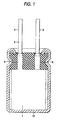
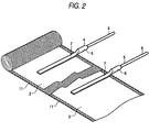
- Figs. 1 and 2 show general structures of aluminum electrolytic capacitors.
- An aluminum foil of a high purity is chemically or electrochemically etched to thereby enlarge the aluminum foil surface.
- This aluminum foil is subjected to a anodizing treatment in an electrolyte such as an aqueous ammonium borate solution to give an anodic electrode foil (2) having an oxide coating layer formed on its surface.
- This anodic electrode foil (2) and a cathodic electrode foil (3) made of an aluminum foil of a high purity having been etched alone, are wound via a separator (11) made of Manila paper, etc. to give a capacitor device (1) as shown in Fig. 2.
- this capacitor device (1) is impregnated with an electrolyte for driving electrolytic capacitors and then put into a bottomed outer case (10) made of aluminum etc., which is then sealed by drawing.
- the anodic electrode foil (2) and the cathodic electrode foil (3) are provided respectively with lead wires (4) and (5), which are electrode-leading means, by stitching, welding, etc.
- the lead wires (4) and (5) each employed as an electrode leading means is composed of a round bar (6) made of aluminum, a connecting member, (7) being in contact with the electrode foil (2) or (3) and an outer connecting member (8) made of a solderable metal which has been fixed at the tip of the round bar (6) by welding, etc.
- sulfolane Although sulfolane has bean known as a high-boiling solvent capable of imparting excellent high temperature life characteristics (JP-A-1-124210 and JP-A-8-31699), it fails to establish the desired characteristics as described above. Thus, sulfolane cannot be employed in vehicle equipments which should have excellent high temperature life characteristics and low temperature properties simultaneously.
- an object of the present invention is to provide an electrolytic capacitor having excellent high temperature life characteristics and excellent low temperature properties and an electrolyte to be used in these electrolytic capacitors.
- Another object of the present invention is to provide an aluminum electrolytic capacitor having excellent high temperature life characteristics and moisture resistance, a low dielectric loss and good low temperature properties.
- the aluminum electrolytic capacitor of the present invention has the same structure as that of the conventional ones, as shown in Figs. 1 and 2.
- a capacitor device (1) is formed by winding an anodic electrode foil (2) and a cathodic electrode foil (3) via a separator (11).
- the anodic electrode foil (2) and the cathodic electrode foil (3) are connected respectively to a lead wire (4) for leading the anode and another lead wire (5) for leading the cathode.
- Those lead wires (4) and (5) are each composed of a connecting meter (7) being in contact with the electrode foil, a round bar (6) having been molded integrally with the connecting member (7), and an outer connecting meter (8) having been fixed at the tip of the round bar (6).
- the connecting member (7) and the round bar (6) are each made of highly pure aluminum while the outer connecting member (8) is made of a solder-plated, copper-plated steel wire. These lead wires (4) and (5) are connected respectively to the electrode foils (2) and (3) at the connecting member (7) by stitching, ultrasonic welding, etc.
- anodic electrode foil (2) use is made of one formed by chemically or electrochemically etching an aluminum foil of a purity of 99 % or above in an acidic solution to thereby enlarge the surface area thereof, and then subjecting the aluminum foil to a anodizing treatment in an aqueous solution of ammonium borate, ammonium phosphate, ammonium adipate, etc. to thereby form an anodic oxidation coating layer on the surface thereof.
- the capacitor device (1) thus constructed is then impregnated with an electrolyte for driving electrolytic capacitors.
- the capacitor device (1) which has been thus impregnated with the electrolyte, is then put into a bottomed outer case (10) made of aluminum.
- the outer case (10) is provided at the opening with a sealer (9) and then sealed by drawing.
- the sealer (9) is made of, for example, an elastic rubber such as butyl rubber having pores through which the lead wires (4) and (5) are to be passed.
- the first electrolyte contains sulfolane and one or more selected from 3-methyl sulfolane and 2,4-dimethyl sulfolane as a solvent.
- the content of sulfolane is preferably from 20 to 70 % by weight, more preferably from 50 to 70 % by weight based on the mixed solvent.
- the total amount of one or more selected from 3-methyl sulfolane and 2,4-dimethyl sulfolane is generally from 30 to 80 % by weight, preferably from 30 to 50 % by weight based on the mixed solvent.
- the second electrolyte contains a mixed solvent containing sulfolane and ⁇ -butyrolactone as a solvent.
- the content of sulfolane is preferably from 40 to 80 % by weight based on the mixed solvent.
- the third electrolyte contains a mixed solvent of ⁇ -butyrolactone and two or more selected from sulfolane, 3-methyl sulfolane, and 2,4-dimethyl sulfolane.
- the total amount of two or more selected from sulfolane, 3-methyl sulfolane, and 2,4-dimethyl sulfolaneone is preferably above 80 % by weight based on the mixed solvent.
- the solvent may further contain other solvents.
- Examples of the other solvents which may be mixed therewith include protic organic porous solvents such as monohydric alcohols (ethanol, propanol, butanol, pentanol, hexanol, cyclobutanol, cyclopentanol, cyclohexanol, benzyl alcohol, etc.), polyhydric alcohols and oxyalcohol compounds (ethylene glycol, propylene glycol, glycerol, methyl cellosolve, ethyl cellosolve, methoxypropylene glycol, dimethoxypropanol, etc.), aprotic organic porous solvents such as amides (N-methylformamide, N,N-dimethylformamide, N-ethylformamide, N,N-diethylformamide, N-methylacetamide, N,N-dimethylacetamide, N-ethylacetamide, N,N-diethylacetamide, hexamethylphosphoric amide, etc
- solute contained in the first electrolyte examples include ammonium salts, amine salts, quaternary ammonium salts and quaternized cyclic amidinium salts containing acid conjugated bases as the anionic component which are commonly employed in electrolytes for driving electrolytic capacitors.
- Examples of the amines contained in the amine salts include primary amines (methylamine, ethylamine, propylamine, butylamine, ethylenediamine, etc.), secondary amines (dimethylamine, diethylamine, dipropylamine, methylethylamine, diphenylamine, etc.) and tertiary amines (trimethylamine, triethylamine, tripropylamine, triphenylamine, 1,8-diazabicyclo(5,4,0)-undecene-7, etc.).
- primary amines methylamine, ethylamine, propylamine, butylamine, ethylenediamine, etc.
- secondary amines dimethylamine, diethylamine, dipropylamine, methylethylamine, diphenylamine, etc.
- tertiary amines trimethylamine, triethylamine, tripropylamine, triphenylamine, 1,
- Examples of the quaternary ammonium contained in the quaternary ammonium salts include tetraalkylammonium (tetramethylammonium, tetraethylammonium, tetrapropylammonium, tetrabutylammonium, methyltriethylammonium, dimethyldiethylammonium, etc.) and pyridium (1-methylpyridium, 1-ethylpyridium, 1,3-diethylpyridium, etc.).
- Examples of the cations contained in the quaternary salts of the cyclic amidine compounds include cations obtained by quaternizing the following compounds: imidazole monocyclic compounds (imidazole homologs such as 1-methylimidazole, 1,2-dimethylimidazole, 1,4-dimethyl-2-ethylimidazole and 1-phenylimidazole; oxyalkyl imidazole derivatives such as 1-methyl-2-oxymethylimidazole and 1-methyl-2-oxyethylimidazole; nitro- and amino-imidazole derivatives such as 1-methyl-4(5)-nitroimidazole and 1,2-dimethyl-5(4)-aminoimidazole; benzoimidazole (1-methylbenzoimidazole, 1-methyl-2-benzylbenzoimidazole, etc.); compounds having 2-imidazoline ring (1-methylimidazoline, 1,2-dimethylimidazoline, 1,2,4-trimethylimidazoline, 1,4-dimethyl-2-
- anionic component examples include conjugated bases of acids such as carboxylic acids (phthalic acid, isophthalic acid, terephthalic acid, maleic acid, benzoic acid, toluic acid, enanthic acid, malonic acid, etc.), phenols, boric acid, phosphoric acid, carbonic acid and silicic acid.
- acids such as carboxylic acids (phthalic acid, isophthalic acid, terephthalic acid, maleic acid, benzoic acid, toluic acid, enanthic acid, malonic acid, etc.), phenols, boric acid, phosphoric acid, carbonic acid and silicic acid.
- the low temperature characteristics can be more improved.
- the quaternized cyclic amidinium salt include those wherein a cationic component such as quaternized imidazolinium or quaternized pyrimidinium is used together with the above-mentioned anionic component.
- the amount of the quaternized cyclic amidinium salt is preferably from 5 to 40 % by weight.
- Examples of the quaternized imidazolinium include 1,3-dimethylimidazolinium, 1,2,3-trimethylimidazolinium, 1,2,3,4-tetramethylimidazolinium, 1-ethyl-3-methylimidazolinium and 1-ethyl-2,3-dimethylimidazolinium.
- Examples of the quaternized pyrimidinium include 1,3-dimethyl-4,5,6-trihydropyrimidinium, 1,2,3-trimethyl-4,5,6-trihydropyrimidinium, 1,2,3,4-tetramethyl-5,6-dihydropyrimidinium, 1-ethyl-3-methyl-4,5,6-trihydropyrimidinium and 1-ethyl-2,3-dimethyl-4,5,6-trihydropyrimidinium.
- salts having a conjugated base of an acid as the anionic compound and a quaternized alkylated imidazoline cation or a quaternized alkylated pyrimidine cation as the cationic component.
- the acid for the conjugated base as the anionic component include phthalic acid, isophthalic acid, terephthalic acid, maleic acid, benzoic acid, toluic acid, enanthic acid, malonic acid, phenols, boric acid, phosphoric acid, carbonic acid and silicic acid.
- the quaternized imidazoliniums or quaternized pyrimidiniums serving as the cationic component include those as cited above concerning the first electrolyte.
- quaternized imidazolinium salts or quaternized pyrimidinium salts having quaternized imidazolinium or quaternized pyrimidinium as the cationic component.
- anionic component include conjugated bases of acids such as carboxylic acids (phthalic acid, isophthalic acid, terephthalic acid, maleic acid, benzoic acid, toluic acid, enanthic acid, malonic acid, etc.), phenols, boric acid, phosphoric acid, carbonic acid and silicic acid.
- the quaternized imidazoliniums or quaternized pyrimidiniums serving as the cationic component include those as cited above concerning the first electrolyte.
- the total amount of the quaternized imidazolinium salts and quaternized pyrimidinium salts is preferably from 5 to 40 % by weight.
- the first to third electrolytes according to the present invention may further contain boric acid-based compounds such as boric acid, complex compounds of boric acid with polysaccharides (mannitol, sorbitol, etc.), complex compounds of boric acid with polyhydric alcohols (ethylene glycol, glycerol, etc.), surfactants, colloidal silica, etc. to thereby improve the voltage proof.
- boric acid-based compounds such as boric acid, complex compounds of boric acid with polysaccharides (mannitol, sorbitol, etc.), complex compounds of boric acid with polyhydric alcohols (ethylene glycol, glycerol, etc.), surfactants, colloidal silica, etc.
- additives thereto in order to lessen leaking current or absorb hydrogen gas.
- the additives include aromatic nitro compounds (p-nitrobenzoic acid, p-nitrophenol, etc.), phosphorus compounds (phosphoric acid, phosphorous acid, polyphosphoric acid, acidic phosphate compounds), oxycarboxylic acid compounds, etc.
- Aluminum electrolytic capacitors with the use of the first and third electrolytes as described above are excellent in high temperature life characteristics and, further, in low temperature characteristics.
- the above-mentioned first electrolyte contains from 20 to 70% of sulfolane in the mixed solvent, still preferable low temperature characteristics can be further improved.
- Aluminum electrolytic capacitors with the use of the second electrolyte of the present invention are excellent in high temperature life characteristics and moisture resistance. Moreover, these electrolytic capacitors have a low dielectric loss and good low temperature characteristics and suffer from little liquid leakage.
- the life characteristics can be more improved.
- the content thereof is larger than 20%, the dielectric loss and the low temperature characteristics are improved. That is to say, excellent high temperature life characteristics, a low dielectric loss and good low temperature characteristics can be achieved, when the content of ⁇ -butyrolactone is from 20 to 60%.
- An electrolyte having a quaternized cyclic amidinium salt dissolved therein would leak in the following manner. Namely, in a conventional electrolytic capacitor, the spontaneous immersion potential of the cathode lead wire (5) is noble as compared with the spontaneous immersion potential of the cathodic electrode foil (3). When a direct current is loaded, therefore, more cathode current passes through the cathode lead wire than through the cathodic electrode foil. When no load is applied, a local cell is formed by the cathode lead wire and the cathode foil and thus a cathode current passes through the cathode lead wire. That is to say, a cathode current passes through the cathode lead wire both in the loaded and unloaded state.
- the hydroxyl ion thus formed by the reduction reaction of the dissolved oxygen or hydrogen ion reacts with a quaternized cyclic amidinium.
- the quaternized cyclic amidinium undergoes ring-opening to give a secondary amine. Because of being highly volatile and less hygroscopic, it is expected that this secondary amine formed in the space between the round bar and the sealer would quickly volatilize without causing liquid leakage.
- ⁇ -butyrolactone employed as the solvent also reacts therewith to give ⁇ -hydroxybutyric acid. That is to say, there are the above-mentioned secondary amine together with this ⁇ -hydroxybutyric acid. Due to the pH value-lowering effect of ⁇ -hydroxybutyric acid, the secondary amine formed by the ring-opening of the quaternized cyclic amidinium undergoes ring-closure to give the quaternized cyclic amidinium salt again.
- the quaternized cyclic amidinium salt thus formed is not volatile but highly hygroscopic, there arises liquid leakage from the space between the round bar of the cathode lead wire and the sealer due to the hygroscopicity of the quaternized cyclic amidinium salt. It is estimated that the liquid leakage proceeds in accordance with the above mechanism based on the analytical data that the leaking liquid is mainly composed of water as the major component and the quaternized cyclic amidinium salt.
- the solvent in contrast thereto, use is made as the solvent of a mixed solvent of sulfolane and at least one meter selected from 3-methyl sulfolane and 2,4-dimethyl sulfolane. Since none of 3-methyl sulfolane, 2,4-dimethyl sulfolane and sulfolane reacts with hydroxyl ion, no compound lowering pH value, as ⁇ -hydroxybutyric acid does, is formed in this case. Thus, the quaternized cyclic amidinium salt is not formed again and the generated secondary amine volatilizes without causing any liquid leakage.
- the solvent of a mixed solvent of sulfolane with ⁇ -butyrolactone In the second electrolyte of the present invention, use is made as the solvent of a mixed solvent of sulfolane with ⁇ -butyrolactone. In the third electrolyte of the present invention, use is made as the solvent of a mixed solvent of ⁇ -butyrolactone and at least two members selected from among sulfolane, 3-methyl sulfolane and 2,4-dimethyl sulfolane. In these cases, the liquid leakage is prevented too.
- hydroxyl ion generated around the round bar of the cathode lead wire reacts with the quaternized cyclic amidinium and thus disappears. Therefore, the amount of the quaternized cyclic amidinium generated again is small and the secondary amine thus formed volatilizes. Thus, the liquid leakage is prevented in this case.
- the electrolyte of the present invention can also prevent this liquid leakage based on the similar mechanism as the one observed in the cathode lead wire part.
- the cathodic electrode foil (3) use can be made of a cathodic electrode foil having formed thereon a coating made of a metal nitride selected from the group consisting of titanium nitride, zirconium nitride, tantalum nitride and niobium nitride or a metal selected from the group consisting of titanium, zirconium, tantalum and niobium by known methods such as metallizing, plating or application.
- the coating generally has a thickness of 0.01 to 0.5 ⁇ m.
- the cathodic electrode foil may be coated with the metal nitride or metal either on the whole surface or a part of the same, for example, on only one face of the foil.
- the spontaneous immersion potential of the cathode foil becomes noble as compared with that of the cathode lead wire and the cathode polarization resistance is lowered.
- the cathode current in the cathode lead wire becomes minor and the formation of hydroxyl ion in the cathode lead wire side is inhibited, which is further appropriate in preventing liquid leakage.
- an aluminum oxide layer by anodic oxidation with the use of an aqueous solution of ammonium borate, ammonium phosphate or ammonium adipate or to form an insulating layer such as a ceramic coating layer composed of Al 2 O 3 , SiO 2 , ZrO 2 , etc. on the surface of at least the round bar (6) of the lead wires (4) and (5).
- the thickness of the insulating layer is generally from 2 to 25 ⁇ m.
- the area constituting the local cell of the cathode lead wire and the cathode foil is reduced.
- the cathode current passing through the cathode lead wire is reduced. In both of these cases, therefore, the formation of hydroxyl ion in the cathode lead wire side is inhibited and the effect of preventing liquid leakage is further improved.
- Tables 1 and 2 show the composition and specific resistance at 30°C and - 40°C of the electrolyte for electrolytic capacitors of each Example.
- Example 1a 65 10(13) 0 25 0 0 323 28k
- Example 2a 60 15(20) 0 25 0 0 320 20k
- Example 1a 0 75 0 25 0 0 285 solidified Comp.
- Example 2a 75 0 0 25 0 0 325 solidified Prior
- Example a 0 0 87 0 0 13 320 solidified * 3-MSL 3-methyl sulfolane.
- SL sulfolane.
- EG ethylene glycol.
- EDMIP 1-ethyl-2,3-dimethylimidazolinium phthalate.
- TMAP tetramethylammonium phthalate.
- AAd ammonium adipate.
- Values in parentheses given in SL content (wt.%) of sulfolane in mixed solvent.
- Example 1a 0 75 0 25 0 0 285 solidified Comp.
- Example 3a 75 0 0 25 3 0 344 solidified Prior
- 2,4-DMSL 2,4-dimethyl sulfolane. Values in parentheses given in SL : content (wt.%) of sulfonate in mixed solvent.
- Example 8a 1 part of p-nitrobenzoic acid 0.3 parts of phosphoric acid ware added to 100 parts of the electrolyte of Example 4a. The electrolyte thus obtained showed specific resistance of 320 ⁇ -cm at 30°C and 14k ⁇ -cm at - 40°C.
- Example 16a 1 part of p-nitrobenzoic acid and 0.3 parts of phosphoric acid were added to 100 parts of the electrolyte of Example 12a. The electrolyte thus obtained showed specific resistance of 328 ⁇ -cm at 30°C and 11k ⁇ -cm at - 40°C.
- the electrolytes of Examples 1a to 15a according to the present invention were comparable or superior in specific resistance at 30°C and - 40°C to the electrolytes of Comparative Examples 1a to 3a with the use of sulfolane, 3-methyl sulfolane or 2,4-dimethyl sulfolane alone and the one of Prior Example with the use of ethylene glycol and ammonium adipate.
- the electrolytes of Examples 2a to 5a, 8a, 10a to 13a and 16a showing a sulfolane content of from 20 to 70% sustained low specific resistance even at - 40°C, which indicates that these electrolytes are usable at - 40°C.
- aluminum electrolytic capacitors were constructed by using the electrolytes of Examples 2a, 5a, 10a and 13a and that of Prior Example.
- the rated values of the aluminum electrolytic capacitors employed herein were 16V-47 ⁇ F and the case size thereof was 6.3mm (diameter) x 5mm.
- the rated voltage was applied onto 25 samples of each electrolytic capacitor at 125°C and the change in electrostatic capacity ( ⁇ C) and the tangent of loss angle (tan ⁇ ) were measured after 2,000 hours and 4,000 hours, Table 3 summarizes the results.
- electrolytic capacitors with the use of the electrolytes of Examples 4a and 11a and an electrolytic capacitor (Comparative Example 4a) with the use of an electrolyte comprising 75% by weight of ⁇ -butyrolactone and 25% by weight of 1-ethyl-2,3-dimethylimidazolinium phthalate were constructed.
- the rated voltage was applied onto 25 samples of each electrolytic capacitor at 85°C under 85% RH and the occurrence of liquid leakage was monitored with the naked eye after 500, 1,000 and 2,000 hours.
- Table 4 summarizes the results.
- the first electrolyte for electrolytic capacitors contains a mixed solvent of at least one member selected from 3-methyl sulfolane and 2,4-dimethyl sulfolane with sulfolane as the solvent.
- Electrolytic capacitors with the use of this electrolyte have excellent high temperature life characteristics and good low temperature characteristics.
- By controlling the content of the sulfolane to 20 to 70% by weight based on the whole solvent further improved low temperature characteristics can be obtained.
- a quaternized cyclic amidinium salt such as a quaternized imidazolinium salt or a quaternized pyrimidinium salt as the solute, the low temperature characteristics can be further improved.
- a quaternized cyclic amidinium salt is used in the electrolyte, no liquid leakage arises.
- a capacitor device is constructed by winding, via a separator (11), an anodic electrode foil (2) and a cathodic electrode foil (3).
- a separator 11
- an anodic electrode foil (2) and a cathodic electrode foil (3) are connected respectively to an anode-leading wire (4) and a cathode-leading wire (5).
- lead wires (4) and (5) are each composed of a connecting member (7) being in contact with the electrode foil, a round bar (6) having been molded integrally with the connecting member (7), and an outer connecting meter (8) having been fixed at the tip of the round bar (6).
- the connecting member (7) and the round bar (6) are each made of aluminum having a purity of 99 % while the outer connecting member (8) is made of a solder-plated, copper-plated steel wire.
- These lead wires (4) and (5) are electrically connected respectively to the electrode foils (2) and (3) at the connecting meter (7) by stitching, ultrasonic welding, etc.
- anodic electrode foil (2) use is made of one prepared by chemically or electrochemically etching an aluminum foil of 99.9 % in purity in an acidic solution to thereby enlarge the area and then subjecting the foil to a anodizing treatment in an aqueous ammonium adipate solution to form an anodic oxidation coating layer thereon.
- cathodic electrode foil (3) use is made of one prepared by etching an aluminum foil of 99.7 % in purity.
- the capacitor device (1) thus constructed is then impregnated with electrolytes for driving aluminum electrolytic capacitors.
- Table 6 shows the composition and electric conductance at 30°C and - 40°C of each electrolyte.
- Composition of Electrolyte (wt.%) Electric Conductance (mS/cm) Sulfolane GBL EDMIP TMAP TEPA 30°C - 40°C
- Example 5b 30 45(60) 25 8.6 0.7
- Example 1b 75 25 3.3 solidified Comp.
- Example 2b 60 15(20) 25 3-1 solidified Comp.
- Example 3b 50 25(33) 25 4.5 0.1 Comp.
- Example 4b 37.5 37.5(53) 25 6.1 0.3 Comp.
- Example 5b 50 25(33) 25 2.0 0.05 *
- GBL ⁇ -butyrolactone.
- EDMIP 1-ethyl-2,3-dimethylimidazolinium phthalate.
- TMAP tetramethylammonium phthalate.
- TEAP triethylammonium phthalate.
- Values in parentheses given in SL content (wt.%) of sulfonate in mixed solvent.
- the electrolytes of Examples 1b to 6b according to the present invention were superior in electric conductance at 30°C and - 40°C to the electrolytes of Comparative Examples 2b to 5b with the use of tetramethylammonium phthalate or triethylammonium phthalate as the solute.
- the capacitor devices (1) were impregnated with the electrolytes of Examples 2b and 6b and that of Prior Example 1b comprising 75 % of ⁇ -butyrolactone and 25 % 1-ethyl-2,3-dimethylimidazolinium phthalate. Next, these capacitor devices each were put into an outer case (10) which was a bottomed tube made of aluminum. Then, the opening of the outer case (10) was sealed with a sealer (9) by drawing.
- the rated values of the aluminum electrolytic capacitors employed thus constructed were 16V-47 ⁇ F and the case size thereof was 6.3mm (diameter) x 5mm.
- the rated voltage was applied onto 25 samples of each of the electrolytic capacitors of Examples 2b and 6b and prior Example 1b at 125°C and the change in electrostatic capacity ( ⁇ C) and the tangent of loss angle (tan ⁇ ) were measured after 1,000 hours and 2,000 hours.
- Table 7 summarizes the results.
- the electrolytic capacitors of Examples 2b and 6b were superior in high temperature life characteristics and sustained low initial tan ⁇ compared with the electrolytic capacitor of Prior Example 1b with the use of ⁇ -butyrolactone alone as the solvent.
- the electrolytic capacitor of Example 2b the ⁇ -butyrolactone content of which in the solvent fell within the range of from 20 to 60% sustained the characteristics at 125°C for 2,000 hours.
- the electrolytic capacitor of Example 6b suffered from deterioration in its characteristics after 2,000 hours.
- electrolytes were prepared by adding 6 % of water content to the electrolytes of Example 2b and Prior Example 1b to give electrolytes of Example 7b and Comparative Example 6b respectively. Then electrolytic capacitors were constructed by the same method as the one described above. 25 samples of each of these electrolytic capacitors were allowed to stand at 125°C and the change in electrostatic capacity ( ⁇ C), the tangent of loss angle (tan ⁇ ) and leaking current (LC) were measured after 1,000 hours and 2,000 hours. Table 8 summarizes the results.
- Example 7b obtained by adding 6 % of water content to the electrolyte of the present invention was superior in all of the items examined (i.e., change in electrostatic capacity, tangent of loss angle and leaking current) to the electrolyte of Comparative Example 6b prepared by adding 6 % of water content to the prior electrolyte, which indicates that the electrolytic capacitor of the present invention has an improved moisture resistance.
- an electrolytic capacitor was constructed in the same manner as in Example 2b except for coating the whole surface of the cathodic electrode foil (3) with titanium nitride by vacuum evaporation method(Example 8b).
- Example 9b Another electrolytic capacitor was constructed in the same manner as in Example 8b except for using an cathodic electrode foil in which an aluminum oxide layer had been formed at least on the surface of the round bar (6) of the lead wires (4) and (5) by anodic oxidation with the use of an aqueous solution of ammonium phosphate (Example 9b).
- Example 2b 1,500 hrs 3,000 hrs 5,000 hrs
- Example 2b 0/25 15/25 25/25
- Example 8b 0/25 0/25 2/25
- Example 9b 0/25 0/25 0/25 Prior
- Example 2b 25/25 - -
- Prior Example 3b 25/25 - -
- the electrolytic capacitor of Example 2b with the use of the electrolyte according to the present invention showed no liquid leakage after 1,500 hours and, therefore, was superior to the electrolytic capacitors of Prior Examples 2b and 3b.
- the electrolytic capacitor of Example 2b achieved good results at 125°C too.
- the electrolytic capacitor of Example 9b, wherein an aluminum oxide layer had been formed on the surface of the round bar of the lead wire in the electrolytic capacitor of Example 8b showed loss liquid leakage.
- the present invention provides an aluminum electrolytic capacitor constructed by winding, via a separator, an anodic electrode foil provided with an anode leading means and a cathodic electrode foil provided with a cathode leading means made of aluminum to form a capacitor device, then impregnating the capacitor device with an electrolyte wherein a quaternized imidazolinium salt or a quaternized pyrimidinium salt is dissolved as the solute in a mixed solvent containing sulfolane and ⁇ -butyrolactone, and then putting the thus impregnated capacitor device in an outer case.
- This electrolytic capacitor is excellent in high temperature life characteristics and moisture resistance. It also excellent in dielectric loss and low temperature characteristics and suffers from little liquid leakage.
- the liquid leakage can be further relieved by using an aluminum foil provided with a coating made of a metal nitride selected from the group consisting of titanium nitride, zirconium nitride, tantalum nitride and niobium nitride or a metal selected from the group consisting of titanium, zirconium, tantalum and niobium formed on the whole surface or apart of the same.
- the liquid leakage characteristics can be further improved by further forming an aluminum oxide layer on the whole surface or a part of the same of the cathode leading means by anodic oxidation.
- Tables 11 to 13 show the composition and specific resistance at 30°C and - 40°C of the electrolyte for electrolytic capacitors of each Example according to the present invention.
- Composition of Electrolyte wt.%) Specific Resistance ( ⁇ -cm) SL 3-MSL GBL EDMIP TMAP 30°C - 40°C
- Example 7c 6 54 15(20) 25 0 223 8.8k
- SL sulfolane.
- 3-MSL 3-methyl sulfolane.
- GBL ⁇ -butyrolactone.
- EDMIP 1-ethyl-2,3-dimethylimidazolinium phthalate.
- TMAP tetramethylammonium phthalate. Values in parentheses given in GBL : content (wt.%) of ⁇ -butyrolactone in mixed solvent.
- Example 2c 32.5 32.5 10(14) 0 25 318 13k Comp.
- Example 26c 28.5 28.5 18(24) 25 0 234 7.0k Comp.
- Example 9c 1 part of p-nitrobenzoic acid and 0.3 parts of phosphoric acid were added to 100 parts of the electrolyte of Example 4c.
- the electrolyte thus obtained showed specific resistance of 246 ⁇ -cm at 30°C and 9.6k ⁇ -cm at - 40°C.
- Example 18c 1 part of p-nitrobenzoic acid and 0.3 parts of phosphoric acid were added to 100 parts of the electrolyte of Example 13c.
- the electrolyte thus obtained showed specific resistance of 268 ⁇ -cm at 30°C and 9.2k ⁇ -cm at - 40°C.
- Example 27c 1 part of-p-nitrobenzoic acid and 0.3 parts of phosphoric acid were added to 100 parts of the electrolyte of Example 22c.
- the electrolyte thus obtained showed specific resistance of 282 ⁇ -cm at 30°C and 8.5k ⁇ -cm at - 40°C.
- aluminum electrolytic capacitors were constructed by using the electrolytes of Examples 2c, 4c, 8c, 11c, 13c, 17c, 20c, 22c and 26c and that of Prior Example c.
- the rated values of the aluminum electrolytic capacitors employed thus constructed were 16V-47 ⁇ F and the case size thereof was 6.3mm (diameter) x 5mm.
- the rated voltage was applied on to 25 samples of each of the electrolytic capacitors at 125°C and the change in electrostatic capacity ( ⁇ C) and the tangent of loss angle (tan ⁇ ) were measured after 2,000 hours and 4,000 hours. Table 14 summarizes the results.
- the electrolytic capacitors of Examples were superior in high temperature life characteristics and sustained low initial tan ⁇ compared with the electrolytic capacitor of Prior Example c.
- the electrolytic capacitors according to the present invention are usable at 125°C for 4,000 hours.
- electrolytic capacitors were constructed by using the electrolytes of Examples 4c, 13c and 22c and Comparative Examples 1c to 3c and another comparative electrolyte (Comparative Example 7c) comprising 75% by weight of ⁇ -butyrolactone and 25% by weight of 1-ethyl-2,3-dimethylimidazolinium phthalate.
- Comparative Example 7c another comparative electrolyte comprising 75% by weight of ⁇ -butyrolactone and 25% by weight of 1-ethyl-2,3-dimethylimidazolinium phthalate.
- the rated voltage was applied at 85°C under 85% RH and the occurrence of liquid leakage was monitored with the naked eye after 500, 1,000 and 2,000 hours. Table 15 shows the results.
- the third electrolyte for electrolytic capacitors according to the present invention is one wherein a mixed solvent of at least two members selected from sulfolane, 3-methyl sulfolane and 2,4-dimethyl sulfolane with ⁇ -butyrolactone is used as the solvent and a quaternized imidazolinium salt or a quaternized pyrimidinium salt is used as the solute.
- the electrolytic capacitor with the use of this electrolyte is excellent in high temperature life characteristics and low temperature characteristics.
- further improved high temperature life characteristics can be obtained by controlling the content of ⁇ -butyrolactone in the mixed solvent to 20% by weight or less based on the whole solvent.
- the eloctrolytic capacitor of the present invention is free from liquid leakage.
Landscapes
- Engineering & Computer Science (AREA)
- Power Engineering (AREA)
- Chemical & Material Sciences (AREA)
- Chemical Kinetics & Catalysis (AREA)
- Electrochemistry (AREA)
- Microelectronics & Electronic Packaging (AREA)
- Electric Double-Layer Capacitors Or The Like (AREA)
Applications Claiming Priority (10)
| Application Number | Priority Date | Filing Date | Title |
|---|---|---|---|
| JP36452797 | 1997-12-18 | ||
| JP36452797 | 1997-12-18 | ||
| JP36714097 | 1997-12-25 | ||
| JP36714097 | 1997-12-25 | ||
| JP05438398A JP4745471B2 (ja) | 1998-02-18 | 1998-02-18 | 電解コンデンサ用電解液およびそれを用いた電解コンデンサ |
| JP5438398 | 1998-02-18 | ||
| JP8252298 | 1998-03-13 | ||
| JP08252298A JP4849701B2 (ja) | 1997-12-25 | 1998-03-13 | 電解コンデンサ用電解液およびそれを用いた電解コンデンサ |
| JP23015898A JP4780812B2 (ja) | 1997-08-01 | 1998-07-31 | アルミニウム電解コンデンサ |
| JP23015898 | 1998-07-31 |
Publications (3)
| Publication Number | Publication Date |
|---|---|
| EP0924722A2 true EP0924722A2 (de) | 1999-06-23 |
| EP0924722A3 EP0924722A3 (de) | 2002-07-31 |
| EP0924722B1 EP0924722B1 (de) | 2009-10-21 |
Family
ID=27523156
Family Applications (1)
| Application Number | Title | Priority Date | Filing Date |
|---|---|---|---|
| EP98124273A Expired - Lifetime EP0924722B1 (de) | 1997-12-18 | 1998-12-18 | Elektrolyt für Elektrolytkondensator und diesen aufweisen der Elektrolytkondensator |
Country Status (4)
| Country | Link |
|---|---|
| US (2) | US6166899A (de) |
| EP (1) | EP0924722B1 (de) |
| KR (1) | KR100608466B1 (de) |
| DE (1) | DE69841249D1 (de) |
Cited By (1)
| Publication number | Priority date | Publication date | Assignee | Title |
|---|---|---|---|---|
| CN111640578A (zh) * | 2020-05-20 | 2020-09-08 | 湖南城市学院 | 一种led用铝电解电容器的工作电解液及其制备方法 |
Families Citing this family (30)
| Publication number | Priority date | Publication date | Assignee | Title |
|---|---|---|---|---|
| US6166899A (en) * | 1997-12-18 | 2000-12-26 | Nippon Chemi-Con Corporation | Electrolyte for electrolytic capacitor and electrolytic capacitor having the same |
| US6515847B1 (en) * | 1998-09-30 | 2003-02-04 | Nippon Chemi-Con Corporation | Solid electrolyte capacitor and its manufacturing method |
| DE69936151T2 (de) * | 1999-03-29 | 2008-01-24 | Nippon Chemi-Con Corp., Ome | Festelektrolytkondensator und herstellungsverfahren |
| US6545858B1 (en) * | 1999-11-30 | 2003-04-08 | Showa Denko K.K. | Capacitor |
| DE10016866C2 (de) * | 2000-04-05 | 2002-03-14 | Epcos Ag | Ethylenglykolmischung, Al-Elektrolyt-Kondensator mit der Ethylenglykolmischung und Verwendung der Ethylenglykolmischung |
| US6452784B2 (en) * | 2000-05-31 | 2002-09-17 | Matsushita Electric Industrial Co., Ltd. | Aluminum electrolytic capacitor and method for producing the same |
| KR100349128B1 (ko) * | 2000-10-16 | 2002-08-17 | 삼성전기주식회사 | 저압용 알루미늄 전해 커패시터의 전해액 및 그 제조방법 |
| EP1394824A4 (de) * | 2001-05-11 | 2008-01-23 | Mitsubishi Chem Corp | Elektrolytische lösung für einen elektrolytkondensator und elektrolytkondensator damit |
| KR20020089685A (ko) * | 2001-05-23 | 2002-11-30 | 삼성전기주식회사 | 알루미늄 전해 콘덴서용 초저임피던스 전해액 및 이를함유하는 전해콘덴서 |
| US6459565B1 (en) * | 2001-06-11 | 2002-10-01 | Kemet Electronics Corporation | Surface mount aluminum capacitor having anode foil anodized in an aqueous phosphate solution |
| DE10128581B4 (de) * | 2001-06-13 | 2005-04-07 | Epcos Ag | Elektrolytlösung für elektrochemische Kondensatoren |
| MY133582A (en) * | 2001-12-18 | 2007-11-30 | Matsushita Electric Industrial Co Ltd | Aluminum electrolytic capacitor and method for producing the same |
| AUPS119502A0 (en) * | 2002-03-19 | 2002-04-18 | Energy Storage Systems Pty Ltd | An electrolyte for an energy storage device |
| JP2004111921A (ja) * | 2002-07-26 | 2004-04-08 | Sanyo Chem Ind Ltd | 電気化学キャパシタ用電解液およびそれを用いた電気化学キャパシタ |
| TWI319585B (en) * | 2002-11-08 | 2010-01-11 | Nippon Chemicon | Electrolytic condenser |
| KR101112022B1 (ko) * | 2002-11-08 | 2012-02-24 | 미쯔비시 가가꾸 가부시끼가이샤 | 전해 콘덴서용 전해액 및 그것을 이용한 전해 콘덴서 |
| US7090762B2 (en) * | 2003-08-05 | 2006-08-15 | Kemet Electronics Corp. | Method of passing electric current through highly resistive anodic oxide films |
| CN100420123C (zh) * | 2004-06-25 | 2008-09-17 | 松下电器产业株式会社 | 使用了电化学电容器的电子设备 |
| DE112007000056T5 (de) * | 2006-09-29 | 2008-08-07 | Matsushita Electric Industrial Co., Ltd., Kadoma | Elektronisches Bauteil und elektronische Steuervorrichtung, die dieses verwendet |
| KR100779263B1 (ko) * | 2007-02-06 | 2007-11-27 | 오영주 | 무극성 금속 전해 커패시터 및 그의 제조방법 |
| US7965492B2 (en) * | 2007-10-19 | 2011-06-21 | Oh Young Joo | Metal capacitor and manufacturing method thereof |
| US8116062B2 (en) * | 2007-10-19 | 2012-02-14 | Oh Young Joo | Metal capacitor to improve electric conductivity |
| US7626802B2 (en) * | 2007-10-19 | 2009-12-01 | Oh Young Joo | Metal capacitor and manufacturing method thereof |
| US8159811B2 (en) * | 2007-10-19 | 2012-04-17 | Oh Young Joo | Metal capacitor and manufacturing method thereof |
| US8203823B2 (en) * | 2008-01-11 | 2012-06-19 | Oh Young Joo | Metal capacitor and manufacturing method thereof |
| US8098479B1 (en) * | 2008-09-19 | 2012-01-17 | Cornell Dubilier Marketing, Inc. | Capacitor having zinc coated common edge with welded aluminum terminal |
| JPWO2011121995A1 (ja) * | 2010-03-31 | 2013-07-04 | 日本ケミコン株式会社 | 固体電解コンデンサ |
| US9536674B2 (en) * | 2012-09-29 | 2017-01-03 | Nippon Chemi-Con Corporation | Electrolytic solution for electrolytic capacitor, and electrolytic capacitor |
| CN112582179B (zh) * | 2019-09-30 | 2022-07-19 | 深圳新宙邦科技股份有限公司 | 一种电解电容器 |
| CN112234270B (zh) * | 2020-11-19 | 2021-12-28 | 广州市云通磁电股份有限公司 | 一种磷酸铁锂电池的化成方法 |
Family Cites Families (17)
| Publication number | Priority date | Publication date | Assignee | Title |
|---|---|---|---|---|
| US4151581A (en) * | 1977-08-04 | 1979-04-24 | Sprague Electric Company | Spacer-electrolyte composite in electrolytic capacitors |
| US4167458A (en) * | 1978-03-28 | 1979-09-11 | Union Carbide Corporation | Lithium ion-containing organic electrolyte |
| CA1143002A (en) * | 1979-06-28 | 1983-03-15 | George E. Blomgren | Organic electrolyte for rechargeable lithium cells |
| DE3004728A1 (de) * | 1980-02-08 | 1981-08-13 | Siemens AG, 1000 Berlin und 8000 München | Aluminium-elektrolytkondensator und verfahren zu seiner herstellung |
| EP0227433B1 (de) * | 1985-12-20 | 1992-01-15 | Mitsubishi Petrochemical Co., Ltd. | Elektrolytische Lösung eines quaternären Ammoniumsalzes für elektrolytische Kondensatoren |
| JPS62288815A (ja) * | 1986-02-21 | 1987-12-15 | Sanyo Chem Ind Ltd | 電解液 |
| US4725927A (en) * | 1986-04-08 | 1988-02-16 | Asahi Glass Company Ltd. | Electric double layer capacitor |
| JPH01214106A (ja) * | 1988-02-23 | 1989-08-28 | Asahi Glass Co Ltd | 電気二重層コンデンサ |
| US5754394A (en) * | 1993-03-22 | 1998-05-19 | Evans Capacitor Company Incorporated | Capacitor including a cathode having a nitride coating |
| JPH06275468A (ja) * | 1993-03-22 | 1994-09-30 | Matsushita Electric Ind Co Ltd | 電気二重層キャパシタ |
| EP0649153B1 (de) * | 1993-10-19 | 1999-05-26 | Matsushita Electric Industrial Co., Ltd. | Ionenleitender Polymerelektrolyt und seine Anwendung in einem Elektrolytkondensator |
| EP0684620B1 (de) * | 1993-12-03 | 2003-06-04 | Sanyo Chemical Industries, Ltd. | Elektrolytloesung und daraus hergestelltes elektrochemisches element |
| JPH0831699A (ja) * | 1994-07-11 | 1996-02-02 | Mitsui Petrochem Ind Ltd | 電解液溶媒及びそれを用いた電解コンデンサ用電解液 |
| RU2089957C1 (ru) * | 1995-03-16 | 1997-09-10 | Открытое акционерное общество "Катион" | Электролитический конденсатор |
| US5827602A (en) * | 1995-06-30 | 1998-10-27 | Covalent Associates Incorporated | Hydrophobic ionic liquids |
| JP3016421B2 (ja) * | 1997-01-13 | 2000-03-06 | 日本ケミコン株式会社 | 電解コンデンサ用アルミニウム陰極箔 |
| US6166899A (en) * | 1997-12-18 | 2000-12-26 | Nippon Chemi-Con Corporation | Electrolyte for electrolytic capacitor and electrolytic capacitor having the same |
-
1998
- 1998-12-17 US US09/213,435 patent/US6166899A/en not_active Expired - Lifetime
- 1998-12-18 DE DE69841249T patent/DE69841249D1/de not_active Expired - Lifetime
- 1998-12-18 KR KR1019980056994A patent/KR100608466B1/ko not_active Expired - Lifetime
- 1998-12-18 EP EP98124273A patent/EP0924722B1/de not_active Expired - Lifetime
-
2000
- 2000-08-17 US US09/641,080 patent/US6274061B1/en not_active Expired - Lifetime
Cited By (1)
| Publication number | Priority date | Publication date | Assignee | Title |
|---|---|---|---|---|
| CN111640578A (zh) * | 2020-05-20 | 2020-09-08 | 湖南城市学院 | 一种led用铝电解电容器的工作电解液及其制备方法 |
Also Published As
| Publication number | Publication date |
|---|---|
| US6274061B1 (en) | 2001-08-14 |
| KR19990063286A (ko) | 1999-07-26 |
| KR100608466B1 (ko) | 2006-10-25 |
| EP0924722B1 (de) | 2009-10-21 |
| DE69841249D1 (de) | 2009-12-03 |
| EP0924722A3 (de) | 2002-07-31 |
| US6166899A (en) | 2000-12-26 |
Similar Documents
| Publication | Publication Date | Title |
|---|---|---|
| US6274061B1 (en) | Electrolyte for electrolytic capacitor and electrolytic capacitor having the same | |
| JP4900456B2 (ja) | アルミニウム電解コンデンサ | |
| JP4780812B2 (ja) | アルミニウム電解コンデンサ | |
| KR102165432B1 (ko) | 전해 콘덴서용 전해액 및 전해 콘덴서 | |
| JP4548553B2 (ja) | アルミニウム電解コンデンサ | |
| JP3872182B2 (ja) | 電気二重層コンデンサ | |
| JP4617529B2 (ja) | 電解コンデンサ | |
| JP4780811B2 (ja) | 電解コンデンサ用電解液およびそれを用いた電解コンデンサ | |
| JP4458208B2 (ja) | 電解コンデンサ用電解液およびそれを用いた電解コンデンサ | |
| JP4849701B2 (ja) | 電解コンデンサ用電解液およびそれを用いた電解コンデンサ | |
| JP4548563B2 (ja) | アルミニウム電解コンデンサ | |
| JP4458209B2 (ja) | 電解コンデンサ用電解液およびそれを用いた電解コンデンサ | |
| JP4745471B2 (ja) | 電解コンデンサ用電解液およびそれを用いた電解コンデンサ | |
| JP2002217068A (ja) | 電解コンデンサ駆動用電解液およびそれを用いた電解コンデンサ | |
| JP4745470B2 (ja) | 電解コンデンサ用電解液およびそれを用いた電解コンデンサ | |
| JP4834207B2 (ja) | 電解コンデンサ用電解液およびそれを用いた電解コンデンサ | |
| JP4632271B2 (ja) | 電解コンデンサ用電解液およびそれを用いてなる電解コンデンサ | |
| JP2001307960A (ja) | アルミニウム電解コンデンサ | |
| JPH11219865A (ja) | 電解コンデンサ用電解液およびそれを用いた電解コンデンサ | |
| JP4258586B2 (ja) | 電解コンデンサ用電解液 | |
| JP4096133B2 (ja) | 電解コンデンサ用電解液 | |
| JP4983072B2 (ja) | 電解コンデンサ | |
| JP2008103752A (ja) | 電解コンデンサ用電解液およびそれを用いた電解コンデンサ | |
| JPH10135081A (ja) | 電解コンデンサ用電解液およびそれを用いた電解コンデンサ | |
| JP3491501B2 (ja) | アルミ電解コンデンサ |
Legal Events
| Date | Code | Title | Description |
|---|---|---|---|
| PUAI | Public reference made under article 153(3) epc to a published international application that has entered the european phase |
Free format text: ORIGINAL CODE: 0009012 |
|
| AK | Designated contracting states |
Kind code of ref document: A2 Designated state(s): AT BE CH CY DE DK ES FI FR GB GR IE IT LI LU MC NL PT SE |
|
| AX | Request for extension of the european patent |
Free format text: AL;LT;LV;MK;RO;SI |
|
| PUAL | Search report despatched |
Free format text: ORIGINAL CODE: 0009013 |
|
| AK | Designated contracting states |
Kind code of ref document: A3 Designated state(s): AT BE CH CY DE DK ES FI FR GB GR IE IT LI LU MC NL PT SE |
|
| AX | Request for extension of the european patent |
Free format text: AL;LT;LV;MK;RO;SI |
|
| 17P | Request for examination filed |
Effective date: 20021106 |
|
| AKX | Designation fees paid |
Designated state(s): DE FR GB |
|
| 17Q | First examination report despatched |
Effective date: 20001101 |
|
| GRAP | Despatch of communication of intention to grant a patent |
Free format text: ORIGINAL CODE: EPIDOSNIGR1 |
|
| GRAS | Grant fee paid |
Free format text: ORIGINAL CODE: EPIDOSNIGR3 |
|
| RAP1 | Party data changed (applicant data changed or rights of an application transferred) |
Owner name: NIPPON CHEMI-CON CORPORATION |
|
| GRAA | (expected) grant |
Free format text: ORIGINAL CODE: 0009210 |
|
| AK | Designated contracting states |
Kind code of ref document: B1 Designated state(s): DE FR GB |
|
| REG | Reference to a national code |
Ref country code: GB Ref legal event code: FG4D |
|
| REF | Corresponds to: |
Ref document number: 69841249 Country of ref document: DE Date of ref document: 20091203 Kind code of ref document: P |
|
| PLBE | No opposition filed within time limit |
Free format text: ORIGINAL CODE: 0009261 |
|
| STAA | Information on the status of an ep patent application or granted ep patent |
Free format text: STATUS: NO OPPOSITION FILED WITHIN TIME LIMIT |
|
| 26N | No opposition filed |
Effective date: 20100722 |
|
| REG | Reference to a national code |
Ref country code: FR Ref legal event code: PLFP Year of fee payment: 18 |
|
| REG | Reference to a national code |
Ref country code: FR Ref legal event code: PLFP Year of fee payment: 19 |
|
| REG | Reference to a national code |
Ref country code: FR Ref legal event code: PLFP Year of fee payment: 20 |
|
| PGFP | Annual fee paid to national office [announced via postgrant information from national office to epo] |
Ref country code: DE Payment date: 20171211 Year of fee payment: 20 Ref country code: FR Payment date: 20171221 Year of fee payment: 20 |
|
| PGFP | Annual fee paid to national office [announced via postgrant information from national office to epo] |
Ref country code: GB Payment date: 20171221 Year of fee payment: 20 |
|
| REG | Reference to a national code |
Ref country code: DE Ref legal event code: R071 Ref document number: 69841249 Country of ref document: DE |
|
| REG | Reference to a national code |
Ref country code: GB Ref legal event code: PE20 Expiry date: 20181217 |
|
| PG25 | Lapsed in a contracting state [announced via postgrant information from national office to epo] |
Ref country code: GB Free format text: LAPSE BECAUSE OF EXPIRATION OF PROTECTION Effective date: 20181217 |