EP0924725A2 - Interrupteur electrique à double contact - Google Patents
Interrupteur electrique à double contact Download PDFInfo
- Publication number
- EP0924725A2 EP0924725A2 EP98120615A EP98120615A EP0924725A2 EP 0924725 A2 EP0924725 A2 EP 0924725A2 EP 98120615 A EP98120615 A EP 98120615A EP 98120615 A EP98120615 A EP 98120615A EP 0924725 A2 EP0924725 A2 EP 0924725A2
- Authority
- EP
- European Patent Office
- Prior art keywords
- contact
- point
- bridge
- support
- pieces
- Prior art date
- Legal status (The legal status is an assumption and is not a legal conclusion. Google has not performed a legal analysis and makes no representation as to the accuracy of the status listed.)
- Withdrawn
Links
Images
Classifications
-
- H—ELECTRICITY
- H01—ELECTRIC ELEMENTS
- H01H—ELECTRIC SWITCHES; RELAYS; SELECTORS; EMERGENCY PROTECTIVE DEVICES
- H01H1/00—Contacts
- H01H1/50—Means for increasing contact pressure, preventing vibration of contacts, holding contacts together after engagement, or biasing contacts to the open position
-
- H—ELECTRICITY
- H01—ELECTRIC ELEMENTS
- H01H—ELECTRIC SWITCHES; RELAYS; SELECTORS; EMERGENCY PROTECTIVE DEVICES
- H01H1/00—Contacts
- H01H1/12—Contacts characterised by the manner in which co-operating contacts engage
- H01H1/14—Contacts characterised by the manner in which co-operating contacts engage by abutting
- H01H1/20—Bridging contacts
Definitions
- the invention relates to a contact pairing with a double contact point for an electrical Switching device according to the preamble of claim 1.
- the contact pieces generally consist of silver-containing or similar material.
- the contact surface is covered by a flat or specially shaped e.g. spherical Surface formed. Typically, this occurs at the actual contact points one point-shaped contact surface each, so that the position is unstable or indifferent is.
- the system is stimulated to vibrate, for example, by the impact of the Contact bridge when switching on the fixed contact pieces.
- the vibrations can subside or persist for a long time. By these vibrations are loaded on the contact bridge; the buzzing that may occur are perceived as disturbing.
- the object of the invention is to have a contact pairing of the type mentioned to design the corresponding contact pieces so that vibrations, excited by Switch-on processes and other effects, e.g. Shocks to be avoided.
- the one contact point has a support point. B. flat, crowned, etc. trained, whereas the other contact point with two defined contact surfaces is trained.
- the two contact surfaces or points of the other contact point are separated from each other by a valley, the extension of which is in the direction of the longitudinal extension the contact bridge runs.
- the three-point support corresponds to a statically determined one Storage.
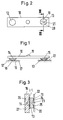
- a contact bridge 10 is formed by an elongated flat strip material, which has an elevation 11 in the middle and one in the area of the two ends Contact piece 12 and 13 carries that with a solder layer 14, 15 on the contact bridge 10 are soldered on.
- One contact piece 12 has a surface 16 through a spherical spherical surface is formed, as a result of which a point-shaped contact surface relative to a fixed contact piece 17 18 is formed.
- the other contact piece 13 has two spherical elevations 19, 20 through a valley 21 are separated from each other, which runs in the longitudinal direction of the contact bridge 10, so that the two elevations 19 and 20 lie on both sides of the longitudinal center line L-L.
- a swing around the longitudinal center line L-L is avoided because the support is a statically determined support. This also prevents the humming and vibrations.
- the shape of the spherical elevations 19 and 20 is not essential; It is advantageous if the distance between the crowned elevations is transverse to the longitudinal extent or becomes as large as possible to the longitudinal center line L-L; it is also convenient to determine the depth of the Tales 21 to be as large as possible in relation to the convex elevations 24 and 25, because there may be erosion in the course of the electrical life.
- the procedure for producing the contact piece 13 is as follows:
- the contact piece 13 is initially flat and is over the solder layer 15 on the contact bridge 10 soldered. Then the contact bridge 10 together with the contact piece 13 deformed so that the elevations 19 and 20 are formed; be there on the contact piece 13 opposite surface of the contact carrier 10 wells 26 and 27 generated.
- the contact pieces are soldered; it there is of course also the possibility that the contact pieces riveted or from the The contact bridge material is punched or pressed and then silver-plated.
Landscapes
- Contacts (AREA)
- Slide Switches (AREA)
Applications Claiming Priority (2)
| Application Number | Priority Date | Filing Date | Title |
|---|---|---|---|
| DE19755930 | 1997-12-17 | ||
| DE1997155930 DE19755930A1 (de) | 1997-12-17 | 1997-12-17 | Kontaktpaarung mit Doppelkontaktstelle für ein elektrisches Schaltgerät |
Publications (2)
| Publication Number | Publication Date |
|---|---|
| EP0924725A2 true EP0924725A2 (fr) | 1999-06-23 |
| EP0924725A3 EP0924725A3 (fr) | 2000-03-22 |
Family
ID=7852133
Family Applications (1)
| Application Number | Title | Priority Date | Filing Date |
|---|---|---|---|
| EP98120615A Withdrawn EP0924725A3 (fr) | 1997-12-17 | 1998-11-02 | Interrupteur electrique à double contact |
Country Status (2)
| Country | Link |
|---|---|
| EP (1) | EP0924725A3 (fr) |
| DE (1) | DE19755930A1 (fr) |
Families Citing this family (13)
| Publication number | Priority date | Publication date | Assignee | Title |
|---|---|---|---|---|
| RU2170983C1 (ru) * | 2000-11-24 | 2001-07-20 | ЗАО "Уралэлектро К" | Электромагнитный коммутационный аппарат |
| RU2170972C1 (ru) * | 2000-11-24 | 2001-07-20 | ЗАО "Уралэлектро К" | Неподвижный контактный узел электромагнитного коммутационного аппарата |
| RU2170984C1 (ru) * | 2000-11-24 | 2001-07-20 | ЗАО "Уралэлектро К" | Электромагнитный коммутационный аппарат |
| RU2170974C1 (ru) * | 2000-11-24 | 2001-07-20 | ЗАО "Уралэлектро К" | Контактный мостик электромагнитного коммутационного аппарата |
| RU2170986C1 (ru) * | 2000-11-24 | 2001-07-20 | ЗАО "Уралэлектро К" | Электромагнитный коммутационный аппарат |
| RU2170973C1 (ru) * | 2000-11-24 | 2001-07-20 | ЗАО "Уралэлектро К" | Узел контактных траверс электромагнитного коммутационного аппарата |
| RU2170985C1 (ru) * | 2000-11-24 | 2001-07-20 | ЗАО "Уралэлектро К" | Электромагнитный коммутационный аппарат |
| RU2294574C2 (ru) * | 2004-09-15 | 2007-02-27 | Открытое акционерное общество "Всероссийский научно-исследовательский проектно-конструкторский и технологический институт релестроения с опытным производством" | Электромагнитный коммутационный аппарат |
| CN201408720Y (zh) | 2008-11-12 | 2010-02-17 | Abb股份有限公司 | 具有接触电桥的电过载继电器 |
| DE102011119306A1 (de) | 2011-11-24 | 2013-05-29 | Daimler Ag | Kontaktpaarung mit einer Doppelkontaktstelle für ein elektrisches Schaltgerät |
| PL3086351T3 (pl) | 2015-04-22 | 2018-02-28 | Ellenberger & Poensgen Gmbh | Przekaźnik mocy dla pojazdu |
| RU167449U1 (ru) * | 2016-06-01 | 2017-01-10 | Российская Федерация, От Имени Которой Выступает Министерство Промышленности И Торговли Российской Федерации | Электромагнитный контактор |
| RU210556U1 (ru) * | 2022-01-12 | 2022-04-21 | Федеральное государственное бюджетное образовательное учреждение высшего образования "Сибирский государственный индустриальный университет" ФГБОУ ВО "СибГИУ" | Контактный мостик электромагнитного коммутационного аппарата |
Family Cites Families (5)
| Publication number | Priority date | Publication date | Assignee | Title |
|---|---|---|---|---|
| DE2022178A1 (de) * | 1970-05-06 | 1971-11-18 | Bbc Brown Boveri & Cie | Kontaktanordnung mit Schaltbruecke |
| DE3329617A1 (de) * | 1982-09-10 | 1984-03-15 | Naimer, Hubert Laurenz, 6612 Ascona | Kontaktanordnung |
| DE3627459A1 (de) * | 1986-06-30 | 1988-01-14 | Schunk Metall & Kunststoff | Schaltelement fuer befehlsgeraete fuer den frontplatteneinbau |
| DE3834155A1 (de) * | 1988-10-07 | 1990-04-12 | Licentia Gmbh | Bewegliche kontaktbruecke fuer ein luftschuetz |
| DE29701312U1 (de) * | 1997-01-28 | 1997-04-10 | Klöckner-Moeller GmbH, 53115 Bonn | Kontaktbrückenhalterung |
-
1997
- 1997-12-17 DE DE1997155930 patent/DE19755930A1/de not_active Withdrawn
-
1998
- 1998-11-02 EP EP98120615A patent/EP0924725A3/fr not_active Withdrawn
Also Published As
| Publication number | Publication date |
|---|---|
| DE19755930A1 (de) | 1999-06-24 |
| EP0924725A3 (fr) | 2000-03-22 |
Similar Documents
| Publication | Publication Date | Title |
|---|---|---|
| DE69602202T2 (de) | Elektrischer kontakt mit verringerter selbstinduktivität | |
| EP0924725A2 (fr) | Interrupteur electrique à double contact | |
| DE1765727B1 (de) | Elektrisches kontaktelement fuer einen leiterplatten-randverbinder | |
| EP0371310B1 (fr) | Procédé de fabrication d'une connexion électrique conductrice avec un conducteur plat | |
| EP0211357B1 (fr) | procédé d'installation d'un dispositif de contact sur une carte de circuits imprimés. | |
| DE102017100724A1 (de) | Elektrisches Einpresskontaktelement | |
| DE19523977A1 (de) | Microchip-Sicherung | |
| EP0332720A1 (fr) | Broche de contact | |
| DE10307934A1 (de) | Anschluß zum elektrischen Anschließen einer Knopfbatterie | |
| WO2020030371A1 (fr) | Ensemble de mise en contact électrique et connecteur électrique | |
| DE2603151B2 (de) | Bauelement für Schalt- und/oder Trennleisten in Verteilern für Fernmeldeanlagen | |
| DE102020001379B3 (de) | Anordnung von Bauteilen zur Übertragung von elektrischem Strom | |
| EP0258664A2 (fr) | Unité pour fixer des lignes électriques dans des distributeurs d'installations de télécommunication | |
| DE2547278C2 (de) | Elektrischer Schnappschalter | |
| DE3237031A1 (de) | Brueckenkontaktanordnung | |
| DE102018216143B3 (de) | Kontaktanordnung und Vorrichtung mit einer Grundplatte und einer darauf angeordneten Kontaktanordnung | |
| WO2002091524A1 (fr) | Connecteur electrique | |
| EP0258629A2 (fr) | Module pour protéger les lignes électriques dans des installations de télécommunication | |
| DE102006043795B3 (de) | Elektrischer Mikroschalter | |
| DE102006062494A1 (de) | Elektrische Vorrichtung mit einem Trägerelement mit zumindest einer speziellen Anschlussfläche und einem oberflächenmontierten Bauelement | |
| EP0854548B1 (fr) | Dispositif de contact électrique | |
| DE10229331B4 (de) | Einpresskontakt | |
| DE3304121C2 (de) | Bimetallschalter | |
| DE3151933A1 (de) | Elektrischer verbinder | |
| DE2147389C3 (de) | Verfahren zum dichten Verschliessen von Oberflächen von Kunststoffkörpern |
Legal Events
| Date | Code | Title | Description |
|---|---|---|---|
| PUAI | Public reference made under article 153(3) epc to a published international application that has entered the european phase |
Free format text: ORIGINAL CODE: 0009012 |
|
| AK | Designated contracting states |
Kind code of ref document: A2 Designated state(s): DE FR IT |
|
| AX | Request for extension of the european patent |
Free format text: AL;LT;LV;MK;RO;SI |
|
| PUAL | Search report despatched |
Free format text: ORIGINAL CODE: 0009013 |
|
| AK | Designated contracting states |
Kind code of ref document: A3 Designated state(s): AT BE CH CY DE DK ES FI FR GB GR IE IT LI LU MC NL PT SE |
|
| AX | Request for extension of the european patent |
Free format text: AL;LT;LV;MK;RO;SI |
|
| AKX | Designation fees paid |
Free format text: DE FR IT |
|
| STAA | Information on the status of an ep patent application or granted ep patent |
Free format text: STATUS: THE APPLICATION IS DEEMED TO BE WITHDRAWN |
|
| 18D | Application deemed to be withdrawn |
Effective date: 20000925 |