EP0924733A2 - Mikrosicherung - Google Patents
Mikrosicherung Download PDFInfo
- Publication number
- EP0924733A2 EP0924733A2 EP98121442A EP98121442A EP0924733A2 EP 0924733 A2 EP0924733 A2 EP 0924733A2 EP 98121442 A EP98121442 A EP 98121442A EP 98121442 A EP98121442 A EP 98121442A EP 0924733 A2 EP0924733 A2 EP 0924733A2
- Authority
- EP
- European Patent Office
- Prior art keywords
- transition piece
- switching contact
- linear actuators
- actuators
- circuit
- Prior art date
- Legal status (The legal status is an assumption and is not a legal conclusion. Google has not performed a legal analysis and makes no representation as to the accuracy of the status listed.)
- Withdrawn
Links
Images


Classifications
-
- H—ELECTRICITY
- H01—ELECTRIC ELEMENTS
- H01H—ELECTRIC SWITCHES; RELAYS; SELECTORS; EMERGENCY PROTECTIVE DEVICES
- H01H71/00—Details of the protective switches or relays covered by groups H01H73/00 - H01H83/00
- H01H71/10—Operating or release mechanisms
- H01H71/12—Automatic release mechanisms with or without manual release
- H01H71/14—Electrothermal mechanisms
- H01H71/145—Electrothermal mechanisms using shape memory materials
-
- H—ELECTRICITY
- H01—ELECTRIC ELEMENTS
- H01H—ELECTRIC SWITCHES; RELAYS; SELECTORS; EMERGENCY PROTECTIVE DEVICES
- H01H61/00—Electrothermal relays
- H01H61/01—Details
- H01H61/0107—Details making use of shape memory materials
-
- H—ELECTRICITY
- H01—ELECTRIC ELEMENTS
- H01H—ELECTRIC SWITCHES; RELAYS; SELECTORS; EMERGENCY PROTECTIVE DEVICES
- H01H1/00—Contacts
- H01H1/0036—Switches making use of microelectromechanical systems [MEMS]
-
- H—ELECTRICITY
- H01—ELECTRIC ELEMENTS
- H01H—ELECTRIC SWITCHES; RELAYS; SELECTORS; EMERGENCY PROTECTIVE DEVICES
- H01H1/00—Contacts
- H01H1/50—Means for increasing contact pressure, preventing vibration of contacts, holding contacts together after engagement, or biasing contacts to the open position
- H01H1/52—Contacts adapted to act as latches
-
- H—ELECTRICITY
- H01—ELECTRIC ELEMENTS
- H01H—ELECTRIC SWITCHES; RELAYS; SELECTORS; EMERGENCY PROTECTIVE DEVICES
- H01H1/00—Contacts
- H01H1/0036—Switches making use of microelectromechanical systems [MEMS]
- H01H2001/0042—Bistable switches, i.e. having two stable positions requiring only actuating energy for switching between them, e.g. with snap membrane or by permanent magnet
- H01H2001/0047—Bistable switches, i.e. having two stable positions requiring only actuating energy for switching between them, e.g. with snap membrane or by permanent magnet operable only by mechanical latching
-
- H—ELECTRICITY
- H01—ELECTRIC ELEMENTS
- H01H—ELECTRIC SWITCHES; RELAYS; SELECTORS; EMERGENCY PROTECTIVE DEVICES
- H01H61/00—Electrothermal relays
- H01H2061/006—Micromechanical thermal relay
-
- H—ELECTRICITY
- H01—ELECTRIC ELEMENTS
- H01H—ELECTRIC SWITCHES; RELAYS; SELECTORS; EMERGENCY PROTECTIVE DEVICES
- H01H61/00—Electrothermal relays
- H01H61/01—Details
- H01H61/0107—Details making use of shape memory materials
- H01H2061/0122—Two SMA actuators, e.g. one for closing or resetting contacts and one for opening them
-
- H—ELECTRICITY
- H01—ELECTRIC ELEMENTS
- H01H—ELECTRIC SWITCHES; RELAYS; SELECTORS; EMERGENCY PROTECTIVE DEVICES
- H01H83/00—Protective switches, e.g. circuit-breaking switches, or protective relays operated by abnormal electrical conditions otherwise than solely by excess current
- H01H83/20—Protective switches, e.g. circuit-breaking switches, or protective relays operated by abnormal electrical conditions otherwise than solely by excess current operated by excess current as well as by some other abnormal electrical condition
- H01H2083/206—Protective switches, e.g. circuit-breaking switches, or protective relays operated by abnormal electrical conditions otherwise than solely by excess current operated by excess current as well as by some other abnormal electrical condition with thermal shunt trip
Definitions
- the present invention relates to a micro fuse (MEMS) for interrupting and closing an electrical Circuit.
- MEMS micro fuse
- the present invention is an automatic fuse with millimeter dimensions using linear actuators made of a shape memory alloy.
- Such fuses form a ikro- M E M lektro- echanisches- S ystem (MEMS) for interrupting and closing an electrical circuit.
- Linear actuators as such are, for example, from: ACTUATOR 96 , 5th International Conference on New Actuators, 26-28 June 1996, Bremen, p.367-369 ". It is especially known to arrange two linear actuators, which consist of a shape memory alloy, biased against one another in order to carry out switching operations. Each of the actuators has a meandering structure, as well as a fixed and a movable end Finally, the actuator is arranged on a ceramic substrate.
- the invention proposes the features before, cited in its entirety in claim 1 are. Further advantageous embodiments of the invention are to be seen in the features of the subclaims.
- the micro-fuse according to the invention enables automatic Interruption of an electrical load circuit above a critical current.
- a load circuit can be a first control circuit be closed again.
- the interruption of the load circuit additionally interrupted as required become.
- the micro fuse can be a very small size of a few mm. It is for its realization only a single SMA micro component required.
- the security function is due to the intrinsic SMA effect very reliable. The movement is smooth, high forces in the contact area with sufficient Travel paths for galvanic contact interruption be achieved.
- Materials made of shape memory alloys FGL show at Transition from a martensitic phase below the Phase transition temperature of the material to an austenitic Parent phase by heating above the phase transition temperature a thermoelastic phase transformation. Is below the phase transformation temperature the shape memory material is plastic by several percent deformable. The material remains in the deformed state, until it is above the phase transformation temperature is heated, taking considerable force back to its original shape (memory shape) assumes. In the martensitic state, Slightly deflect resilient SMA components when heated on the other hand, they take on the phase transformation temperature a much stiffer condition. This effect is also called a one-way effect because it only changes when the temperature changes occurs in one direction (warming).
- the Memory shape can be determined by certain thermomechanical Procedure can be set.
- a technically interesting shape memory material is e.g. B. NiTi, which allows reversible elongation changes up to 8%.
- the new micro fuse is for interrupting and closing of an electrical circuit in microtechnology intended.
- As an actuator it has at least two levels, counteracting linear actuators (actuator), one first 1 and a second 2, each made of two meandering Structures 3, 4 and 5, 6 as control elements.
- the control elements consist of two folded ones, for example Planar springs, which are connected to one another via a transition piece 9 are coupled and are mechanically biased Condition. Both planar springs from FGL are conditioned in such a way that they are austenitic High temperature phase either an undeflected or assume fully deflected shape of memory.
- the Use embodiments shown in Figures 1 to 4 an undeflected shape of memory.
- Both actuators 1, 2 each have a stationary 7 and a movable one End of work 8, the two movable through Transition piece 9 are interconnected.
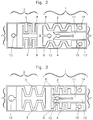
- the transition piece 9 forms simultaneously as a common part both actuators 1, 2 the connection between the structures 3, 4 and 5, 6. All of these elements as well as the calotte 10 consist as part of a structured film electrically conductive SMA, in the phase transformation in the actuators 1, 2 forces in each other opposite direction are generated. These powers are released by ohmic heating because of the structure is partly part of circuits and therefore partially heated above the phase transformation temperature can be. To do this, play in the to 3 shown execution of the micro fuse two Circuits matter. The first is the one to be switched Load or circuit.
- the second circuit is a control circuit for closing the load circuit by the first actuator 1, the transition piece 9 and the connections 14, 15 is formed.
- the switch contact 10, 11 is designed as a releasable clamping device in the load circuit, which is the reversible opening and closing of the electrical and mechanical connection in the load circuit.
- the clamping device 10, 11 is dimensioned so that that the contact at low currents in Load circuit can be maintained and the contact resistance is sufficiently lowered.
- the actuators 1, 2 of the two circuits are designed that when current is applied to the actuator 1 and open Switching contact 10.11 in the control circuit the force in Actuating direction of the actuator 1 with respect to the restoring force the actuator 2 and the holding force of the switching contact 10, 11 predominates. It also predominates at currents above the limiting current in the load circuit is the restoring force of the actuator 2 relative to the force of the actuator 1 in the direction of adjustment and the clamping force.
- the limit current in Load circuit is determined by the dimensions of the actuator 2.
- the transition piece 9 between the two actuators 1, 2 is dimensioned so that both actuators 1, 2 thermally are sufficiently decoupled from one another so that at Current applied to the actuator 1 in the control circuit, the temperature of the actuator 2 below its phase transformation temperature remains.
- the Switching contact from parts 10, 11 switched into the load circuit by changing the shape of one of the two Actuators 1, 2 opened and by changing the shape of each other is closed again.
- the first of the actuators 1 consists of the two side by side Structures 3, 4 at their working ends 8 with each other by means of the transition piece 9 are connected.
- the switching contact 10, 11 arranged, one half 10 of the switch contact 10, 11 on the transition piece 9 between the workers 8 electrically conductive, the other half 11 between the Structures 3, 4 of the first actuator 1, but electrical attached separately from this and the rest of the structure is.
- FIG. 1 shows the exemplary embodiment shown, built on a non-conductive substrate plate 16.
- Both actuators 1, 2 with the transition piece 9 and the spherical cap 10 attached to it form a freely movable one SMA actuator between the fixed contact elements 17, 18, 19, in which the connections 12, 14, 15 sit tight. In this way the ends mentioned of the actuators 1, 2 relative to the substrate plate 16 fixed in place.
- the distance between the contact elements 17, 18, 19 is selected so that the actuators 1, 2 to a certain extent are biased against each other.
- FIG. 4 shows a second embodiment of the micro fuse shown according to the invention. This is with the in Figures 1 to 3 shown execution in all position digits identical to 19, but with an additional one third actuator 20 extended.
- This actuator 20 out two meandering structures 21, 22 is on the transition piece 9 parallel to the second actuator 2 next to this attached with his working end 23 so that he with the Transition piece 9 together as a separate circuit forms the second control circuit.
- This second control circuit enables the separate loosening of the switching contact 10, 11 without heating or influencing the actuator 2 in the load circuit.
- the structures 21, 22 of the additional actuator 20 also have connections 24, 25 which, like that of other actuators 1, 2 in contact elements 26, 27 on the Sit substrate plate 16.
- foils or rolled sheets of SMA As a starting material for the production of the entire structure thin films, foils or rolled sheets of SMA with typical thicknesses D in the area from 20 to 200 ⁇ m. Thin films made of SMA can be sputtered and subsequent thermomechanical treatment getting produced. Foils made of SMA in the thickness range of 50 ⁇ m z. B. with the "melt spinning" process will be realized. Films can now be rolled SME sheets produced by melt metallurgy in all Thickness ranges can be realized. Within certain limits the thickness can also be determined by chemical etching desired value can be set.
- the microstructuring of the starting material into the desired one Shape of the structure of the micro fuse can be by Laser cutting, eroding or by a lithographic Procedures are carried out.
- a lithographic process especially the electrolytic photoetching process prefers.
- a suitable photoresist is applied the material applied, which is then optically cast by shadows or exposed to direct laser writing and is subsequently developed.
- the microstructured so generated Photoresist serves as a protective mask for the following one electrolytic etching process in which the unprotected Parts in an electrolytic bath in the presence of a electrical field can be selectively removed. Because of the high chemical resistance of SMA materials The electrolytic etching processes are particularly suitable here Well.
Landscapes
- Thermally Actuated Switches (AREA)
- Fuses (AREA)
Abstract
Description
- 1
- erster Aktor, 1.Steuerkreis
- 2
- zweiter Aktor Lastkreis
- 3
- mäanderförmige Struktur
- 4
- mäanderförmige Struktur
- 5
- mäanderförmige Struktur
- 6
- mäanderförmige Struktur
- 7
- ortfestes Ende
- 8
- bewegliches Arbeitsende
- 9
- Übergangsstück
- 10
- Kalotte Schaltkontakt
- 11
- Klemmvorrichtung Schaltkontakt
- 12
- Anschluß
- 13
- Anschluß
- 14
- Anschluß
- 15
- Anschluß
- 16
- Substratplatte
- 17
- Kontaktelemente
- 18
- Kontaktelemente
- 19
- Kontaktelemente
- 20
- dritter Aktor, 2.Steuerkreis
- 21
- mäanderförmige Struktur
- 22
- mäanderförmige Struktur
- 23
- bewegliches Arbeitsende
- 24
- Anschluß
- 25
- Anschluß
- 26
- Kontaktelemente
- 27
- Kontaktelemente
Claims (7)
- Mikrosicherung (MEMS), zum Unterbrechen und Schließen eines elektrischen Stromkreises mit den folgenden Merkmalen:a) die Mikrosicherung weist mindestens zwei ebene, gegeneinander vorgespannte Linearaktoren (1, 2) aus mäanderförmigen Strukturen (3, 4, 5, 6) als Stellelemente mit je einen ortsfestem (7) und einem beweglichen (8) Arbeitsende aus strukturierter Folie einer elektrisch leitfähigen Formgedächtnislegierung FGL auf,b) in den Stellelementen (3, 4, 5, 6) werden durch Phasentransformation Kräfte in einander entgegengesetzter Richtung erzeugtc) die Stellelemente (3, 4, 5, 6) sind zum Teil Bestandteil des elektrischen Stromkreises,d) die gegeneinander liegenden Arbeitsenden (8) der Linearaktoren (1, 2) sind durch ein Übergangsstück (9) miteinander verbunden, wobei an dem Übergangsstück (9) ein Schaltkontakt (10, 11) in dem elektrischen Stromkreis angeordnet ist,e) der Schaltkontakt (10, 11) durch die Formänderung eines der Linearaktoren (1, 2) geöffnet und durch die Formänderung des anderen der Linearaktoren wieder geschlossen wird.
- Mikrosicherung nach Anspruch 1, gekennzeichnet durch die weiteren Merkmale:a) der erste Linearaktor (1) besteht aus mindestens zwei nebeneinanderliegenden, mäanderförmigen Strukturen (3, 4), die an ihren Arbeitsenden (8) über das Übergangsstück (9) miteinander verbunden sind und zwischen oder neben sich den Schaltkontakt (10, 11) aufnehmen,b) dabei ist die eine Hälfte (10) des Schaltkontaktes (10, 11) an dem Übergangsstück (9) elektrisch leitend, die andere Hälfte (11) zwischen oder neben den mäanderförmigen Strukturen (3, 4) des ersten Linearaktors (1), jedoch elektrisch von diesen und der übrigen Struktur getrennt angebracht.
- Mikrosicherung nach Anspruch 2, gekennzeichnet durch die weiteren Merkmale:a) die eine Hälfte des Schaltkontaktes (10, 11) besteht aus einer Kalotte (10), die andere Hälfte des Schaltkontaktes (10, 11) aus einer diese Kalotte (10) aufnehmende Klemmvorrichtung (11), deren Klemmkraft durch die Formänderung je eines der Linearaktoren (1, 2) beim Öffnen und Schließen in beiden Richtungen überwindbar ist.
- Mikrosicherung nach Anspruch 2 oder 3, gekennzeichnet durch die weiteren Merkmale:a) der über das Übergangsstück (9) mit dem Schaltkontakt (10, 11) verbundene zweite Linearaktor (2) ist Bestandteil des Strompfades des zu schaltenden Strom-/Lastkreises, der um den Schaltkontakt (10, 11) gelegene erste Linearaktor (1) bildet einen davon getrennten ersten Steuerkreis mit einem eigenen Strompfad.
- Mikrosicherung nach Anspruch 4, gekennzeichnet durch die weiteren Merkmale:a) an dem Übergangsstück (9) ist parallel zu dem zweiten Linearaktor (2) neben diesem ein dritter Linearaktor (20) aus zwei mäanderförmigen Strukturen (21, 22) mit deren Arbeitsenden (23) angebracht, die mit dem Übergangsstück (9) zusammen einen separaten Stromkreis als zweiten Steuerkreis bilden.
- Mikrosicherung nach Anspruch 5, gekennzeichnet durch die weiteren Merkmale:a) alle Linearaktoren (1, 2, 20) und der dadurch betätigte Schaltkontakt (10, 11) sind gemeinsamer Bestandteil der strukturierten Folie aus der Formgedächtnislegierung FGL, wobei die Linearaktoren (1, 2; 20) dabei jedoch thermisch weitgehend voneinander entkoppelt sind.
- Mikrosicherung nach einem der Ansprüche 3 oder 6, gekennzeichnet durch die weiteren Merkmale:a) die offenen Enden an dem ortsfesten Ende aller Linearaktoren (1, 2; 20) sind als Kontakte (12, 14, 15; 24, 25) ausgebildet, mittels derer die mäanderförmigen Strukturen (3, 4, 5, 6; 21, 22) der Linearaktoren (1, 2; 20) durch Stromaufgabe erwärmbar sind.
Applications Claiming Priority (2)
| Application Number | Priority Date | Filing Date | Title |
|---|---|---|---|
| DE1997157024 DE19757024C1 (de) | 1997-12-20 | 1997-12-20 | Mikrosicherung |
| DE19757024 | 1997-12-20 |
Publications (2)
| Publication Number | Publication Date |
|---|---|
| EP0924733A2 true EP0924733A2 (de) | 1999-06-23 |
| EP0924733A3 EP0924733A3 (de) | 2000-05-24 |
Family
ID=7852837
Family Applications (1)
| Application Number | Title | Priority Date | Filing Date |
|---|---|---|---|
| EP98121442A Withdrawn EP0924733A3 (de) | 1997-12-20 | 1998-11-11 | Mikrosicherung |
Country Status (2)
| Country | Link |
|---|---|
| EP (1) | EP0924733A3 (de) |
| DE (1) | DE19757024C1 (de) |
Cited By (1)
| Publication number | Priority date | Publication date | Assignee | Title |
|---|---|---|---|---|
| WO2003088292A1 (en) * | 2002-04-09 | 2003-10-23 | Microsaic Systems Limited | Microengineered self-releasing switch |
Families Citing this family (6)
| Publication number | Priority date | Publication date | Assignee | Title |
|---|---|---|---|---|
| US6917276B1 (en) | 2000-06-19 | 2005-07-12 | Simpler Networks | Bistable switch with shape memory metal |
| DE10062704A1 (de) * | 2000-12-15 | 2002-07-04 | Siemens Ag | Elektromechanisches Bauelement |
| DE102017124885B4 (de) | 2017-10-24 | 2021-10-28 | Memetis Gmbh | Fernsteuerbare Kupplung insbesondere Modellbahnkupplungen |
| DE102019204846A1 (de) * | 2019-04-04 | 2020-10-08 | Memetis Gmbh | Aktuator-Vorrichtung |
| DE102020213648A1 (de) * | 2020-10-29 | 2022-05-05 | Memetis Gmbh | Aktor und Optikbaugruppe mit Aktor |
| DE102024111548B4 (de) * | 2024-04-24 | 2026-04-16 | Lear Corporation | Serpentinenförmige Formgedächtnislegierungs-Aktuatorbaugruppe |
Family Cites Families (3)
| Publication number | Priority date | Publication date | Assignee | Title |
|---|---|---|---|---|
| GB2182747B (en) * | 1985-11-07 | 1989-10-04 | Gen Electric Plc | Actuator |
| US4811564A (en) * | 1988-01-11 | 1989-03-14 | Palmer Mark D | Double action spring actuator |
| DE19525475B4 (de) * | 1995-02-06 | 2005-10-13 | Bayerische Motoren Werke Ag | Sicherungsvorrichtung für eine Stromleitung in Fahrzeugen |
-
1997
- 1997-12-20 DE DE1997157024 patent/DE19757024C1/de not_active Expired - Fee Related
-
1998
- 1998-11-11 EP EP98121442A patent/EP0924733A3/de not_active Withdrawn
Cited By (1)
| Publication number | Priority date | Publication date | Assignee | Title |
|---|---|---|---|---|
| WO2003088292A1 (en) * | 2002-04-09 | 2003-10-23 | Microsaic Systems Limited | Microengineered self-releasing switch |
Also Published As
| Publication number | Publication date |
|---|---|
| DE19757024C1 (de) | 1999-06-02 |
| EP0924733A3 (de) | 2000-05-24 |
Similar Documents
| Publication | Publication Date | Title |
|---|---|---|
| DE3531710C2 (de) | Durch Zusammenbau von Modulelementen realisierbare Schaltvorrichtung mit veränderlicher Zusammensetzung | |
| DE2106732C3 (de) | Elektrische Membran-Tastatur | |
| DE102019204846A1 (de) | Aktuator-Vorrichtung | |
| DE2515185B2 (de) | Elektrischer Schnappschalter | |
| EP0924733A2 (de) | Mikrosicherung | |
| EP3915153B1 (de) | Aktor mit rückstellfedern | |
| EP1130615B1 (de) | Schaltschloss für einen Niederspannungs-Leistungsschalter | |
| DE1765920B2 (de) | Kontaktanordnung fur elektrische Schaltgerate | |
| WO1999028094A1 (de) | Mikrogreifer | |
| DE102010036215A1 (de) | Elektrischer Leistungsschalter | |
| DE202020104004U1 (de) | Elektrisches Verbindungsschaltglied | |
| DE69714408T2 (de) | Magnetischer Mikroschalter und Herstellungsverfahren | |
| DE10015598A1 (de) | Mikroaktoranordnung | |
| DE2934837A1 (de) | Thermischer ausschalter und verfahren zum montieren einer anzahl dieser ausschalter | |
| WO2002049059A1 (de) | Elektromechanisches bauelement | |
| DE60217802T2 (de) | Durch niedrige Spannung gesteuertes Mikroschaltbauelement | |
| DE2732723C2 (de) | Elektrische Schaltvorrichtung | |
| EP1292961B1 (de) | Schaltereinrichtung mit einem aktuatorelement aus einer form-gedächtnis-legierung | |
| EP2071293B1 (de) | Positionssensor | |
| DE2528502A1 (de) | Schalter mit zwei schaltstellungen | |
| EP0975058A2 (de) | Kontaktvorrichtung | |
| DE102020118270A1 (de) | Elektrisches Verbindungsschaltglied | |
| DE19629482C1 (de) | Schaltkontaktanordnung mit einer Gelenkanordnung für einen Kontakthebel | |
| DE102006051424B4 (de) | Schlossmechanismus für elektrisches Gerät | |
| DE2450742C2 (de) | Elektrischer Schalter |
Legal Events
| Date | Code | Title | Description |
|---|---|---|---|
| PUAI | Public reference made under article 153(3) epc to a published international application that has entered the european phase |
Free format text: ORIGINAL CODE: 0009012 |
|
| AK | Designated contracting states |
Kind code of ref document: A2 Designated state(s): AT BE CH DE FR GB LI LU NL |
|
| AX | Request for extension of the european patent |
Free format text: AL;LT;LV;MK;RO;SI |
|
| PUAL | Search report despatched |
Free format text: ORIGINAL CODE: 0009013 |
|
| AK | Designated contracting states |
Kind code of ref document: A3 Designated state(s): AT BE CH CY DE DK ES FI FR GB GR IE IT LI LU MC NL PT SE |
|
| AX | Request for extension of the european patent |
Free format text: AL;LT;LV;MK;RO;SI |
|
| 17P | Request for examination filed |
Effective date: 20000420 |
|
| AKX | Designation fees paid |
Free format text: AT BE CH DE FR GB LI LU NL |
|
| GRAP | Despatch of communication of intention to grant a patent |
Free format text: ORIGINAL CODE: EPIDOSNIGR1 |
|
| STAA | Information on the status of an ep patent application or granted ep patent |
Free format text: STATUS: THE APPLICATION IS DEEMED TO BE WITHDRAWN |
|
| 18D | Application deemed to be withdrawn |
Effective date: 20041113 |