EP0924794B1 - Antenne rétractable pour téléphone mobile - Google Patents
Antenne rétractable pour téléphone mobile Download PDFInfo
- Publication number
- EP0924794B1 EP0924794B1 EP98402796A EP98402796A EP0924794B1 EP 0924794 B1 EP0924794 B1 EP 0924794B1 EP 98402796 A EP98402796 A EP 98402796A EP 98402796 A EP98402796 A EP 98402796A EP 0924794 B1 EP0924794 B1 EP 0924794B1
- Authority
- EP
- European Patent Office
- Prior art keywords
- strip
- rod
- mobile telephone
- housing
- roll
- Prior art date
- Legal status (The legal status is an assumption and is not a legal conclusion. Google has not performed a legal analysis and makes no representation as to the accuracy of the status listed.)
- Expired - Lifetime
Links
- 239000004020 conductor Substances 0.000 claims description 5
- 239000011810 insulating material Substances 0.000 claims description 3
- 239000000463 material Substances 0.000 claims description 2
- RYGMFSIKBFXOCR-UHFFFAOYSA-N Copper Chemical compound [Cu] RYGMFSIKBFXOCR-UHFFFAOYSA-N 0.000 description 1
- 238000010276 construction Methods 0.000 description 1
- 239000011889 copper foil Substances 0.000 description 1
- 239000000758 substrate Substances 0.000 description 1
Images

Classifications
-
- H—ELECTRICITY
- H01—ELECTRIC ELEMENTS
- H01Q—ANTENNAS, i.e. RADIO AERIALS
- H01Q11/00—Electrically-long antennas having dimensions more than twice the shortest operating wavelength and consisting of conductive active radiating elements
- H01Q11/02—Non-resonant antennas, e.g. travelling-wave antenna
- H01Q11/08—Helical antennas
- H01Q11/086—Helical antennas collapsible
-
- H—ELECTRICITY
- H01—ELECTRIC ELEMENTS
- H01Q—ANTENNAS, i.e. RADIO AERIALS
- H01Q1/00—Details of, or arrangements associated with, antennas
- H01Q1/12—Supports; Mounting means
- H01Q1/22—Supports; Mounting means by structural association with other equipment or articles
- H01Q1/24—Supports; Mounting means by structural association with other equipment or articles with receiving set
- H01Q1/241—Supports; Mounting means by structural association with other equipment or articles with receiving set used in mobile communications, e.g. GSM
- H01Q1/242—Supports; Mounting means by structural association with other equipment or articles with receiving set used in mobile communications, e.g. GSM specially adapted for hand-held use
- H01Q1/243—Supports; Mounting means by structural association with other equipment or articles with receiving set used in mobile communications, e.g. GSM specially adapted for hand-held use with built-in antennas
- H01Q1/244—Supports; Mounting means by structural association with other equipment or articles with receiving set used in mobile communications, e.g. GSM specially adapted for hand-held use with built-in antennas extendable from a housing along a given path
-
- H—ELECTRICITY
- H01—ELECTRIC ELEMENTS
- H01Q—ANTENNAS, i.e. RADIO AERIALS
- H01Q5/00—Arrangements for simultaneous operation of antennas on two or more different wavebands, e.g. dual-band or multi-band arrangements
- H01Q5/40—Imbricated or interleaved structures; Combined or electromagnetically coupled arrangements, e.g. comprising two or more non-connected fed radiating elements
Definitions
- This invention relates to a retractable antenna for a hand held mobile telephone.
- Antennas for satellite reception are typically larger than those used for terrestrial reception- for example an antenna for a medium earth orbit satellite (MEO) is typically 10 cms long and 1 cm in diameter and usually consists of two or four conductors in helical arrangement for transmitting and receiving a circularly polarized wave.
- MEO medium earth orbit satellite
- US patent 5,612,707 is devoted to a helical antenna which may be manipulated to change characteristics of the antenna, in particular to steer the beam of the antenna.
- an antenna made by a conductor 36 deposited on dielectric sheet 30 The step of the helical antenna is varied by furling and unfurling of the dielectric sheet.
- An example of a mechanism to furl and unfurl the dielectric sheet 30 is given in relation to figures 8 and 10.
- An outer side of the sheet is fixed all along a radome 32, 55 which is rotated by a motor 59 that drives rotationally the radome through gears 56, 57, furling and unfurling the dielectric sheet 30.”
- a mobile telephone has a housing and an antenna comprising a strip of flexible insulating material having provided thereon a plurality of lines of conductive material, the strip being formed into a roll with one outer end at the outside of the roll and an inner end inside the roll, and guide means for controlling a movement of the strip.
- the antenna being retractable and by the guide means including a nut on the housing and a threaded rod extending through the centre of the roll into the interior of the phone housing, the rod being engaged and co-acting with said nut, the rod being connected to the inner end of the strip so as to extend the strip outwardly into an elongated cone as the rod is withdrawn from the housing.
- the antenna In the rolled condition, the antenna is suitable for use for GSM and weak satellite signals.
- the conductive lines In the extended position, the conductive lines form a tapering helical array suitable for use as a high gain ICO satellite antenna which enable to transmit and receive a circularly polarized wave.
- Guide means are preferably provided for controlling the movement of the strip between its extended and retracted positions.
- Such guide means may be in the form of a threaded rod extending through the centre of the roll into the interior of the phone housing on which the antenna is mounted.
- the rod engages with a nut fixed on the housing so that it rotates in a predetermined manner as the rod is withdrawn from the housing, the rod be coupled to the inner end of the strip so as draw it outwardly as the rod is withdrawn.
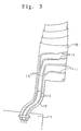
- the antenna comprises an elongate strip of flexible insulating material such as strip 10 of flexible printed circuit substrate material.
- strip 10 Formed on this strip is a series of parallel lines 11 of flexible conductive material, such as thin copper foil lines. Preferably there are four such lines which are parallel to one another and extend along the length of the flexible strip 10.
- the strip 10 is provided at one end with a flexible extension 12 as shown in Figure 3.
- the four lines 11 on the strip are merged into two lines 13 on the extension at microstrip splitters 14 on the strip 10.
- the extension 12 is clamped to a printed circuit board 15 within the mobile telephone case and the two lines 13 are soldered to pads on the printed circuit board.
- the strip 10 Adjacent the splitters 14 on the strip, there is provided on the strip 10 a pivot which extends into a hole in a nut 19 on the phone housing to form a pivotal connection.
- the strip 10 is formed into roll with the pivot boss on the outside. In its rolled condition the strip has one end within the roll and this end can be drawn out to extend the antenna into an elongated cone.
- This inner end of the strip is connected to one end of a guide rod 17 which extends through the roll into the interior of the mobile telephone housing 18.
- the rod is formed with a raised helical thread 17 a which co-acts with the nut 19 fixed on the housing 18.
- the rod 17 When the rod 17 is pulled out of a housing using a knob 20 on the end of the rod 17, the rod 17 is twisted in a predetermined fashion because of the engagement of the thread 17 a with the nut 19, so that the end of the strip is guided as it the antenna is extended to ensure that the proper conical extended shape is achieved.
- the pivotal connection between the outer end of the strip 10 and the housing allows the end of the strip 10 to tip as the antenna extends.
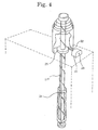
- Figure 4 shows another embodiment of the antenna in accordance with the present invention.
- Rod 17 b is driven up and down by the rotation of nut 25 which is rotatably fixed at the place and rotated by motor 21 through bolt 22.
- Rod 17 b has straight notch along its axis to prevent the rotation of rod 17 b with latch 24 which project into the notch.
Landscapes
- Physics & Mathematics (AREA)
- Electromagnetism (AREA)
- Engineering & Computer Science (AREA)
- Computer Networks & Wireless Communication (AREA)
- Support Of Aerials (AREA)
- Details Of Aerials (AREA)
- Telephone Set Structure (AREA)
Claims (6)
- Téléphone mobile ayant un logement (18) et une antenne comprenant une bande (10) de matériau isolant flexible présentant sur celle-ci une pluralité de lignes (11) de matériau conducteur, la bande (10) étant formée en un rouleau avec une extrémité externe à l'extérieur du rouleau et une extrémité interne à l'intérieur du rouleau, et des moyens de guidage pour contrôler un mouvement de la bande (10),
caractérisé en ce que l'antenne est rétractable et en ce que les moyens de guidage comprennent un écrou (19) fixé sur le logement (18) et une tige filetée (17) s'étendant à travers le centre du rouleau à l'intérieur du logement de téléphone (18), la tige (17) étant en prise et agissant conjointement avec ledit écrou (19), la tige (17) étant reliée à l'extrémité interne de la bande de sorte à étendre la bande vers l'extérieur dans un cône allongé lorsque la tige (17) est retirée du logement. - Téléphone mobile selon la revendication 1, dans lequel la bande (10) est formée d'un matériau de circuit imprimé flexible.
- Téléphone mobile selon l'une quelconque des revendications précédentes, comprenant en outre des moyens de guidage pour faire tourner ladite extrémité interne de la bande (10) lorsqu'elle est retirée du rouleau.
- Téléphone mobile selon l'une quelconque des revendications précédentes, dans lequel l'extrémité externe de la bande enroulée (10) est reliée de façon pivotante au logement (18) du téléphone.
- Téléphone mobile selon l'une quelconque des revendications précédentes, dans lequel ledit écrou (19) est mis en rotation par un moteur (21) dont la direction de rotation est convertible.
- Téléphone mobile selon la revendication 5, dans lequel ladite tige (17b) a une encoche droite le long d'un axe de ladite tige, et un verrou (24) qui fait saillie dans ladite encoche.
Applications Claiming Priority (2)
| Application Number | Priority Date | Filing Date | Title |
|---|---|---|---|
| GB9724445 | 1997-11-20 | ||
| GB9724445A GB2331630B (en) | 1997-11-20 | 1997-11-20 | Retractable antenna for a mobile telephone |
Publications (3)
| Publication Number | Publication Date |
|---|---|
| EP0924794A2 EP0924794A2 (fr) | 1999-06-23 |
| EP0924794A3 EP0924794A3 (fr) | 2000-08-02 |
| EP0924794B1 true EP0924794B1 (fr) | 2006-06-21 |
Family
ID=10822303
Family Applications (1)
| Application Number | Title | Priority Date | Filing Date |
|---|---|---|---|
| EP98402796A Expired - Lifetime EP0924794B1 (fr) | 1997-11-20 | 1998-11-12 | Antenne rétractable pour téléphone mobile |
Country Status (6)
| Country | Link |
|---|---|
| US (1) | US6054960A (fr) |
| EP (1) | EP0924794B1 (fr) |
| JP (1) | JP3226032B2 (fr) |
| KR (1) | KR100278462B1 (fr) |
| GB (1) | GB2331630B (fr) |
| NO (1) | NO985371L (fr) |
Families Citing this family (12)
| Publication number | Priority date | Publication date | Assignee | Title |
|---|---|---|---|---|
| AUPR452601A0 (en) * | 2001-04-23 | 2001-05-24 | M & S Smith Pty Ltd | Helical antenna |
| AU2002248994B8 (en) * | 2001-04-23 | 2008-06-12 | Syntonic Technologies Pty Ltd | Helical antenna |
| KR100677428B1 (ko) * | 2005-01-29 | 2007-02-02 | 엘지전자 주식회사 | 이동통신 단말기 |
| JP2009171343A (ja) * | 2008-01-17 | 2009-07-30 | Panasonic Electric Works Co Ltd | 警報器 |
| WO2015057786A1 (fr) * | 2013-10-16 | 2015-04-23 | Elgan Steven L | Étui de dispositif électronique portatif protecteur à dispositif d'extension |
| EP3552318B1 (fr) | 2016-12-09 | 2020-09-30 | Telefonaktiebolaget LM Ericsson (publ) | Système d'antenne amélioré pour système mimo massif distribué |
| US11564188B2 (en) | 2017-10-17 | 2023-01-24 | Telefonaktiebolaget Lm Ericsson (Publ) | Distributed MIMO synchronization |
| US11616540B2 (en) | 2017-11-21 | 2023-03-28 | Telefonaktiebolaget Lm Ericsson (Publ) | Antenna arrangement for distributed massive MIMO |
| CN110324462B (zh) * | 2018-03-30 | 2021-06-15 | Oppo广东移动通信有限公司 | 电子设备及其控制方法 |
| WO2020078537A1 (fr) * | 2018-10-16 | 2020-04-23 | Telefonaktiebolaget Lm Ericsson (Publ) | Atténuation de perturbation dans un système de communication sans fil |
| WO2021160570A1 (fr) | 2020-02-10 | 2021-08-19 | Telefonaktiebolaget Lm Ericsson (Publ) | Procédé et appareil de communications radio |
| EP4104321B1 (fr) | 2020-02-10 | 2024-09-18 | Telefonaktiebolaget Lm Ericsson (Publ) | Compensation de fonction de transfert de signal de guides d'ondes diélectriques |
Citations (2)
| Publication number | Priority date | Publication date | Assignee | Title |
|---|---|---|---|---|
| US5612707A (en) * | 1992-04-24 | 1997-03-18 | Industrial Research Limited | Steerable beam helix antenna |
| US6184844B1 (en) * | 1997-03-27 | 2001-02-06 | Qualcomm Incorporated | Dual-band helical antenna |
Family Cites Families (16)
| Publication number | Priority date | Publication date | Assignee | Title |
|---|---|---|---|---|
| US3649394A (en) * | 1969-04-03 | 1972-03-14 | Hughes Aircraft Co | 3-dimensional cone antenna method |
| US3863404A (en) * | 1973-08-09 | 1975-02-04 | Building Components Research I | Building Construction |
| US3863405A (en) * | 1974-01-25 | 1975-02-04 | Ametek Inc | Self-erecting tube device |
| US4117495A (en) * | 1977-03-01 | 1978-09-26 | Hochstein Peter A | Self-tuning deployable antenna |
| DE3036084A1 (de) * | 1980-09-25 | 1982-04-29 | Robert Bosch Gmbh, 7000 Stuttgart | Stabantenne, insbesondere fuer ukw-rundfunkempfang |
| US4435716A (en) * | 1981-09-14 | 1984-03-06 | Adrian Zandbergen | Method of making a conical spiral antenna |
| GB2106717B (en) * | 1981-09-22 | 1985-07-03 | Plessey Co Ltd | A self-erecting waveguide antenna |
| US4447816A (en) * | 1981-11-25 | 1984-05-08 | Rca Corporation | Stiffening clamp for self-erecting antenna |
| US4725845A (en) * | 1986-03-03 | 1988-02-16 | Motorola, Inc. | Retractable helical antenna |
| FR2624656B1 (fr) * | 1987-12-10 | 1990-05-18 | Centre Nat Etd Spatiales | Antenne de type helice et son procede de realisation |
| US5198831A (en) * | 1990-09-26 | 1993-03-30 | 501 Pronav International, Inc. | Personal positioning satellite navigator with printed quadrifilar helical antenna |
| US5216436A (en) * | 1991-05-31 | 1993-06-01 | Harris Corporation | Collapsible, low visibility, broadband tapered helix monopole antenna |
| US5541617A (en) * | 1991-10-21 | 1996-07-30 | Connolly; Peter J. | Monolithic quadrifilar helix antenna |
| US5828348A (en) * | 1995-09-22 | 1998-10-27 | Qualcomm Incorporated | Dual-band octafilar helix antenna |
| JP2000500315A (ja) * | 1995-11-15 | 2000-01-11 | アルゴン・アーベー | 携帯無線通信機用小型アンテナ及びそのスイッチレスアンテナ接続手段 |
| US5872549A (en) * | 1996-04-30 | 1999-02-16 | Trw Inc. | Feed network for quadrifilar helix antenna |
-
1997
- 1997-11-20 GB GB9724445A patent/GB2331630B/en not_active Expired - Fee Related
-
1998
- 1998-11-12 EP EP98402796A patent/EP0924794B1/fr not_active Expired - Lifetime
- 1998-11-17 JP JP32683698A patent/JP3226032B2/ja not_active Expired - Fee Related
- 1998-11-18 NO NO985371A patent/NO985371L/no not_active Application Discontinuation
- 1998-11-19 KR KR1019980049753A patent/KR100278462B1/ko not_active Expired - Fee Related
- 1998-11-20 US US09/197,027 patent/US6054960A/en not_active Expired - Fee Related
Patent Citations (2)
| Publication number | Priority date | Publication date | Assignee | Title |
|---|---|---|---|---|
| US5612707A (en) * | 1992-04-24 | 1997-03-18 | Industrial Research Limited | Steerable beam helix antenna |
| US6184844B1 (en) * | 1997-03-27 | 2001-02-06 | Qualcomm Incorporated | Dual-band helical antenna |
Also Published As
| Publication number | Publication date |
|---|---|
| EP0924794A3 (fr) | 2000-08-02 |
| US6054960A (en) | 2000-04-25 |
| GB2331630B (en) | 2001-12-05 |
| JPH11225009A (ja) | 1999-08-17 |
| KR19990045419A (ko) | 1999-06-25 |
| NO985371D0 (no) | 1998-11-18 |
| NO985371L (no) | 1999-05-21 |
| JP3226032B2 (ja) | 2001-11-05 |
| GB9724445D0 (en) | 1998-01-14 |
| KR100278462B1 (ko) | 2001-01-15 |
| GB2331630A (en) | 1999-05-26 |
| EP0924794A2 (fr) | 1999-06-23 |
Similar Documents
| Publication | Publication Date | Title |
|---|---|---|
| EP0924794B1 (fr) | Antenne rétractable pour téléphone mobile | |
| KR100447003B1 (ko) | 복합안테나 | |
| US5189435A (en) | Retractable motorized multiband antenna | |
| AU683907B2 (en) | An antenna arrangement | |
| JP3580654B2 (ja) | 共用アンテナおよびこれを用いた携帯無線機 | |
| DE69924104T2 (de) | Asymmetrische Dipolantennenanordnung | |
| EP0920075B1 (fr) | Antenne a polarisation circulaire grand angle | |
| EP0945917A2 (fr) | Agencement d'antenne et appareil terminal mobile | |
| US5717409A (en) | Dual frequency band antenna system | |
| EP0227804A1 (fr) | Antenne mobile multipolaire axiale | |
| AU734079B2 (en) | Bent-segment helical antenna | |
| WO1997039493A1 (fr) | Dispositif radio portable | |
| JPS61502579A (ja) | 伸縮自在アンテナ | |
| GB2185635A (en) | Antenna for a motor vehicle for am-fm-cellular telephone multiband transmissions/receptions | |
| WO1998005090A9 (fr) | Antenne helicoidale a segment coude | |
| WO1994021002A1 (fr) | Systeme de commande pour antennes orientables mecaniquement | |
| EP0323726A2 (fr) | Antenne à large bande | |
| JP3122017B2 (ja) | 複合アンテナ装置 | |
| JP3662465B2 (ja) | 角型スパイラルアンテナ | |
| US6219008B1 (en) | Antenna connector for radio communication equipment | |
| KR20010072684A (ko) | 미끄럼 커넥터수단을 구비한 안테나장치 | |
| JP3481801B2 (ja) | 平面アンテナおよびこれを用いた携帯無線機 | |
| JPH0117846Y2 (fr) | ||
| JP3407837B2 (ja) | 携帯無線機 | |
| JPH118512A (ja) | 低姿勢アンテナ |
Legal Events
| Date | Code | Title | Description |
|---|---|---|---|
| PUAI | Public reference made under article 153(3) epc to a published international application that has entered the european phase |
Free format text: ORIGINAL CODE: 0009012 |
|
| AK | Designated contracting states |
Kind code of ref document: A2 Designated state(s): FR SE |
|
| AX | Request for extension of the european patent |
Free format text: AL;LT;LV;MK;RO;SI |
|
| PUAL | Search report despatched |
Free format text: ORIGINAL CODE: 0009013 |
|
| AK | Designated contracting states |
Kind code of ref document: A3 Designated state(s): AT BE CH CY DE DK ES FI FR GB GR IE IT LI LU MC NL PT SE |
|
| AX | Request for extension of the european patent |
Free format text: AL;LT;LV;MK;RO;SI |
|
| 17P | Request for examination filed |
Effective date: 20010116 |
|
| AKX | Designation fees paid |
Free format text: FR SE |
|
| REG | Reference to a national code |
Ref country code: DE Ref legal event code: 8566 |
|
| 17Q | First examination report despatched |
Effective date: 20041027 |
|
| GRAP | Despatch of communication of intention to grant a patent |
Free format text: ORIGINAL CODE: EPIDOSNIGR1 |
|
| GRAS | Grant fee paid |
Free format text: ORIGINAL CODE: EPIDOSNIGR3 |
|
| GRAA | (expected) grant |
Free format text: ORIGINAL CODE: 0009210 |
|
| AK | Designated contracting states |
Kind code of ref document: B1 Designated state(s): FR SE |
|
| REG | Reference to a national code |
Ref country code: SE Ref legal event code: TRGR |
|
| ET | Fr: translation filed | ||
| PLBE | No opposition filed within time limit |
Free format text: ORIGINAL CODE: 0009261 |
|
| STAA | Information on the status of an ep patent application or granted ep patent |
Free format text: STATUS: NO OPPOSITION FILED WITHIN TIME LIMIT |
|
| 26N | No opposition filed |
Effective date: 20070322 |
|
| PGFP | Annual fee paid to national office [announced via postgrant information from national office to epo] |
Ref country code: SE Payment date: 20081107 Year of fee payment: 11 |
|
| PGFP | Annual fee paid to national office [announced via postgrant information from national office to epo] |
Ref country code: FR Payment date: 20081112 Year of fee payment: 11 |
|
| EUG | Se: european patent has lapsed | ||
| REG | Reference to a national code |
Ref country code: FR Ref legal event code: ST Effective date: 20100730 |
|
| PG25 | Lapsed in a contracting state [announced via postgrant information from national office to epo] |
Ref country code: FR Free format text: LAPSE BECAUSE OF NON-PAYMENT OF DUE FEES Effective date: 20091130 |
|
| PG25 | Lapsed in a contracting state [announced via postgrant information from national office to epo] |
Ref country code: SE Free format text: LAPSE BECAUSE OF NON-PAYMENT OF DUE FEES Effective date: 20091113 |