EP0924835A2 - Poste de charge et méthode - Google Patents
Poste de charge et méthode Download PDFInfo
- Publication number
- EP0924835A2 EP0924835A2 EP98811225A EP98811225A EP0924835A2 EP 0924835 A2 EP0924835 A2 EP 0924835A2 EP 98811225 A EP98811225 A EP 98811225A EP 98811225 A EP98811225 A EP 98811225A EP 0924835 A2 EP0924835 A2 EP 0924835A2
- Authority
- EP
- European Patent Office
- Prior art keywords
- rail
- pins
- truck
- charging
- battery
- Prior art date
- Legal status (The legal status is an assumption and is not a legal conclusion. Google has not performed a legal analysis and makes no representation as to the accuracy of the status listed.)
- Withdrawn
Links
Images
Classifications
-
- H—ELECTRICITY
- H02—GENERATION; CONVERSION OR DISTRIBUTION OF ELECTRIC POWER
- H02J—ELECTRIC POWER NETWORKS; CIRCUIT ARRANGEMENTS OR SYSTEMS FOR SUPPLYING OR DISTRIBUTING ELECTRIC POWER; SYSTEMS FOR STORING ELECTRIC ENERGY
- H02J7/00—Circuit arrangements for charging or discharging batteries or for supplying loads from batteries
- H02J7/70—Circuit arrangements for charging or discharging batteries or for supplying loads from batteries characterised by the mechanical construction
- H02J7/751—Circuit arrangements for charging or discharging batteries or for supplying loads from batteries characterised by the mechanical construction concerning the insertion or the connection of the batteries
-
- H—ELECTRICITY
- H02—GENERATION; CONVERSION OR DISTRIBUTION OF ELECTRIC POWER
- H02J—ELECTRIC POWER NETWORKS; CIRCUIT ARRANGEMENTS OR SYSTEMS FOR SUPPLYING OR DISTRIBUTING ELECTRIC POWER; SYSTEMS FOR STORING ELECTRIC ENERGY
- H02J2105/00—Networks for supplying or distributing electric power characterised by their spatial reach or by the load
- H02J2105/30—Networks for supplying or distributing electric power characterised by their spatial reach or by the load the load networks being external to vehicles, i.e. exchanging power with vehicles
-
- Y—GENERAL TAGGING OF NEW TECHNOLOGICAL DEVELOPMENTS; GENERAL TAGGING OF CROSS-SECTIONAL TECHNOLOGIES SPANNING OVER SEVERAL SECTIONS OF THE IPC; TECHNICAL SUBJECTS COVERED BY FORMER USPC CROSS-REFERENCE ART COLLECTIONS [XRACs] AND DIGESTS
- Y10—TECHNICAL SUBJECTS COVERED BY FORMER USPC
- Y10S—TECHNICAL SUBJECTS COVERED BY FORMER USPC CROSS-REFERENCE ART COLLECTIONS [XRACs] AND DIGESTS
- Y10S320/00—Electricity: battery or capacitor charging or discharging
- Y10S320/34—Robot, hybrid, recreational or emergency vehicle
Definitions
- the present invention relates to in-track charging stations for charging the batteries of track-mounted lifting assemblies and more particularly to a system for charging batteries of ceiling-mounted lifts that is compatible for use with continuous or jointed rail systems.
- a conventional patient transport system includes a truck that travels along ceiling-mounted rails, for example, running between a bed and a tub or toilet, and a load carrier suspended from the truck.
- the load carrier can be moved manually or equipped with drive motors for moving the truck along the rails and for powering a lifting and lowering mechanism.
- One or more batteries are included in the load carrier for supplying power to the drive motors.
- the batteries are electrically connectable to a charging unit via means provided on the truck and/or rails.
- a charging, or parking, station 1 is disposed in a rail and positioned at a terminal end thereof.
- a local or remote charging unit (not shown) is connected to the charging station 1.
- the engaging end 3 of the charging station has elements 5 for effecting electrical engagement with complementary elements 6 provided on one end of a movable truck 11.
- the mating elements 5, 6 typically include spring-loaded prongs 7 extending from the charging station 1 and mating contacts 9 provided on the movable truck 11. When engaged with the contacts 9, the prongs 7 deliver current from the charging unit to the batteries (not shown) via electrical conductors 13 extending between the contacts 9 and the batteries.
- the truck 11 and the charging station 1 are provided with securing means 15, such as an extension 17 engageable in a receiving channel 19 with spring-loaded balls 18 for releasably holding the truck 11 in a charging position.
- the system shown in Figure 1 has certain disadvantages and limitations.
- the charging station is disposed in the path of travel of the truck, and therefore can only be positioned at an end of the rail.
- the number of possible charging stations is limited, as only one end of the truck is typically equipped with the necessary mating elements and no intermediate stations are possible.
- the inclusion of mating means on one end of the truck increases the length of the truck, necessitating a larger turning radius for the truck and thereby imposing design limitations on the rail system.
- the mating mechanical and electrical elements of the system shown in Figure 1 occasionally become disengaged so that battery charging is interrupted.
- a typical patient transport device having a continuous charging system is disclosed in U.S. Patent No. 5,138,953.
- a transportation device includes bus bars in the form of copper strips on top of insulating layers fastened to the insides of vertically-extending side walls of each rail. Carbon brushes extending from the sides of a movable truck bear against the copper strips and tap the DC voltage at the copper strips. Current is continuously transferred via conductors extending between the brushes and the battery and drive motors. While the device disclosed in U.S. Patent No. 5,138,953 provides for charging of the battery at any position along the rail, it is not cost effective and is subject to failure, particularly when used in combination with jointed rail systems, as the brushes can become damaged when traversing joints in the rails.
- a first embodiment is a charging system as defined in claim 1.
- Preferred embodiments thereof are as defined in claims 2 - 6.
- the invention provides for a battery charging system as defined in claim 7, preferred embodiments being as defined in claims 8 - 17.
- the invention provides for a method of charging a battery of a patient transportation unit as defined in claim 18 with a preferred embodiment as specified in claim 19.
- the present invention provides for a method of and an apparatus for charging batteries of ceiling-mounted lifts.
- Multiple in-track charging stations comprising spaced contact plates are positioned at predetermined locations along the upper interior horizontal surfaces of a rail assembly.
- a short truck having a pair of spring-loaded pins extending from an upper surface thereof and a load carrier suspended from a bolt passing through the carrier traverses the entire rail assembly unencumbered.
- a rail mounted assembly is located for convenience within the rail and the truck is positioned such that the spring-loaded pins extending from the upper surface of the truck press against respective ones of the contact plates of the charging station.
- the plates are secured by conductive screws which are recessed slightly below the surfaces of the plates.
- An audible “click” and tactile “feel” provide the user with indications that the pins are properly engaged with the recessed contact screws.
- the charging system includes a truck-mounted assembly and at least one rail-mounted charging station.
- the truck-mounted assembly includes a truck body having roller pairs provided on opposite sides thereof. Bores extend through the truck body from top to bottom thereof. Each bore houses a spring-loaded pin assembly, which includes a pin that is biased upwardly such that the upper end of the pin extends above the upper surface of the truck body. An electrical lead is soldered to the lower end of the pin, with the free end thereof exiting the bore through the lower surface of the truck body and ultimately terminating at the batteries to be charged. Insulating bushings are provided in the bores for preventing electrical shorts to the truck body.
- Each rail-mounted assembly includes conductive plates, such as brass strips, that are joined to the lower horizontal surface of a cross-piece of the rail.
- An insulator is positioned between the strips and the rail.
- Contact screws extend through holes provided in the brass strips, the insulator and the horizontal cross-piece of the rail for connecting the strips and insulator to the rail and for providing a current path from a local or remote charging unit to the inside of the rail.
- Insulating bushings are disposed in the holes extending through the rail to prevent electrical short circuiting to the rail.
- the truck assembly freely traverses the rail system, with the contact pins spaced from the horizontal cross-piece of the rail by a short distance in their fully extended positions.
- the pins engage beveled ends of the contact plates so as to be cammed inwardly against the pressure of the biasing springs to insure a reliable electrical contact between the pins and contact plates.
- the truck is positioned such that the pins, which are slightly depressed, press against the heads of the contact screws. In that position, a continuous current path from the charging unit to the battery is established.
- An important advantage of the battery charging system of the present invention is that it provides for the implementation of multiple charging locations along a continuous or jointed rail system. This is particularly advantageous to those operating the transport system independently. Users can customize new transport systems or retrofit existing systems to enable recharging of the batteries at locations where the unit is typically left for extended periods of time. Inasmuch as no docking or mating elements are required at the ends of the mobile unit, the truck body can be made substantially smaller than those of the prior art systems, thereby enabling the truck to more easily negotiate curves in the rail and allowing for smaller radii of curvature when designing rail systems.
- the present invention is also superior to prior art continuous charging systems in that it can be used with jointed rail systems and provides for dependable charging. In addition, the present charging system is less prone to being inadvertently disconnected since the spring-biased pins tend to retain the truck in the charging position rather than bias it away from the charging position.
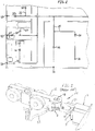
- FIG. 2 illustrates a multiple room structure having a patient transportation system provided therein.
- the system includes interconnected (i.e., jointed) ceiling-mounted rails 21 positioned for supporting a sling or other carrier device 10 carrying a patient to and from important locations, including over a bed 23 or adjacent a toilet 25 and tub 27.
- a truck 29 (FIG. 3) having a conventional load carrier (not shown) suspended from a hanger 20 traverses the rails 21.
- the present invention provides for the installation of charging stations 31 at any point along the rails 21.
- the charging stations 31 are mounted to the rails 21 but do not impede travel of the truck 29 along the rails 21.
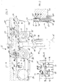
- FIG. 3 is a longitudinal sectional view of the in-track charging system of the present invention which is generally referred to by reference numeral 35.
- the charging system 35 includes a pin assembly 37 integrated with the movable truck 29 and one or more rail-mounted charging stations 39.
- each of the rails 21 along which the truck 29 travels and to which the charging stations 31 are secured is of generally channel-shape.
- Each rail 21 has a horizontal cross-piece 39, side walls 41 extending downwardly from the cross-piece 39, and bottom portions or lips 43 extending inwardly from lower ends of the side walls 41 such that the bottom portions 43 run parallel to the cross-piece 39.
- a load carrier (not shown) housing a battery 45 and drive motors (not shown) is movable along the rails 21. Specifically, the load carrier is suspended from the movable truck 29 by a support bolt 47 and hanger 20.
- the truck 29 includes a main truck body 49 having a top 51, a bottom 53, a front 55, a back 57 and left and right sides 59, 61 (FIG. 4).
- Rollers 63 such as wheels made of a low-friction material, are connected to the left and right sides 59, 61 and have a diameter slightly greater than the top to bottom height of the body 49. The rollers 63 rest upon and travel along the bottom portions 43 of the rail 21. Stops or other means are provided to prevent the truck 29 from traveling off the ends of the rail 21.
- the truck 29 includes a pair of bores 65 (only one shown in FIG. 5) for housing spring-loaded pin assemblies 37.
- Each bore 65 extends generally vertically through the truck body 49.
- a contact pin 67 is positioned in each bore 65 such that its upper end projects beyond the top 51 of the truck body 49. As shown in phantom lines to the left of FIG. 3, the pins 67, when in their fully extended positions, do not contact the horizontal cross-piece 39 of the rail 21.
- the pins 67 When the truck 29 moves into a "charging position" beneath a charging assembly 31, the pins 67 are pressed slightly inwardly. When the truck 29 is moved away from the charging assembly 31, the pins 67 return to their fully extended positions.
- each bore 65 for urging the pin 67 upwardly and for allowing vertical displacement of the pin 67.
- Such urging means is preferably a spring 69 positioned in a lower portion of the bore 65, with one end of the spring 69 connected to or abutting a lower end, or base 75, of the pin 67.
- the length of the spring 69, as well as the design of the bore 65 and the pin 67, are selected to prevent the pin 67 from exiting the truck body 49 through the opening in the top 51 thereof.
- each bore 65 includes a smaller diameter upper bore portion 71 and a larger diameter lower bore portion 73.
- the pin base 75 has a narrow shank portion 77 extending upwardly therefrom through the upper bore portion 71 and beyond the top 51 of the truck body 49.
- the spring 69 is positioned in the lower bore portion 73 and urges the pin 67 upwardly.
- a plastic bushing 79 or other insulating means is provided at least along the walls of the bore 65 surrounding the pin 67 for preventing electrical short circuiting against the truck body 49. It is understood that other biasing means and designs for the pins and bores may be used in the present system, and that embodiments of the present system incorporating such modifications are considered to be within the scope of the present invention.
- a wiring cable 81 connects pins 67 to the battery 45 to be charged.
- Each wire 83 of the cable 81 extends into a bore 65 of the truck body 49 through an opening in the bottom 53 of the truck body 49.
- Each wire 83 passes up through the lower bore portion 73 of the bore 65 and is connected to the lower end 75, or base, of the pin 67.
- the wires 83 are preferably soldered to the pins 67.
- the pin assembly 37 is readily a replaceable by securing removable blocks 85 to the bottom 53 of the truck body 49 beneath the bores 65.
- Each block 85 includes a passage 89 for providing access to the bore 65 in the truck body 49.
- a fastener 87 such as a screw, is provided for removably connecting the block 85 to the truck body 49.
- the entire pin assembly 37, or any part thereof, may be removed and replaced by unlocking or otherwise disengaging the fasteners 87 securing the blocks 85 to the truck body 49.
- the pins 67 and springs 69 are no longer supported in the bores 65 and can be removed therefrom.
- charging station assemblies 31 are positioned in the passage defined by the rail 21 but do not impede travel of the truck 29 therethrough.
- Each assembly 31 includes an insulator strip 91 mounted on the lower surface 93 of the horizontal cross-piece 39 of the rail 21.
- the insulator strip 91 is preferably about one-eighth of an inch thick and is made of polycarbonate or any other acceptable insulating material.
- Metallic plates 95 preferably made of copper or brass, are mounted to the outer surface 97 of the insulator strip 91. Conductive screws 99 extend through the outer surface 101 of the metallic plates 95. As best shown in FIG.
- the insulator strip 91 has a longitudinal recess 103 provided along its lower central surface 97, with the depth of the recess 103 being substantially equal the thickness of the metallic plates 95.
- the outer surface 101 of each metallic plate 95 is substantially flush with the outer surface 97 of the insulator strip 91.
- the metallic plates 95 are spaced apart for electrically isolating each metallic plate from one another.
- lateral edges 105 of the insulator strip 91 are bevelled to provide a "ramp," such that when the truck 29 initially meets the charging assembly 31, the pins 67 are cammed by the edges 105 and gradually pressed inwardly.
- lateral edges 107 of the plates 95 are also bevelled following the slope of the lateral edges 105 of the insulator strip 91.
- the edges 105 of the insulator strip 91 and, if appropriate, the metallic plates 95 preferably slope inwardly at about a 32° angle.
- the insulator strip 91 and the metallic plates 95 lying in the recess 103 of the insulator strip 91 are fastened to the lower surface 93 of the horizontal cross-piece 39 of the rail 21.
- Mounting holes 111 are provided through the horizontal cross-piece 39 of the rail 21, the insulator strip 91, and the metallic plates 95 for receiving fasteners or conductive screws 99 therethrough.
- the holes 111 are aligned such that a single fastener 99 extends through a single mounting hole 111 in each component when the charging station 31 is assembled
- the insulator strip 91 may serve as the drill template for drilling the mounting holes 111 in the rail 21.
- the screws 99 for fastening the insulator strip 91 and the metallic plates 95 to the rail 21 may also serve as the conductive path for delivering current to the charging station 31 in the rail 21.
- the screws 99 are preferably flat head screws countersunk into the metallic plates 95 and insulator strip 91.
- Wires 121 extending from a charging unit 123 are connected to the ends of the screws 99 by a pair of conductive nuts 133, 135.
- the wires are preferably arranged in a harness connected to a charging unit 123.
- a screw post insulator 137 is provided in each mounting hole 111 in the rail 21 for preventing short circuiting of the screws 99 to the rail 21.
- Visual identification means are preferably provided along the outer exposed surfaces of the rails to indicate locations where charging stations are present.
- Such indicating means include, but are not limited to, stickers and other printed media. Additional means such as an audible signal or lights may be provided for indicating that charging of the battery is taking place or that the transportation unit is in a charging position.
- the present invention operates as follows. Multiple charging stations are positioned at predetermined locations along a rail assembly.
- the movable truck having spring-loaded pins extending from an upper surface thereof and a load carrier suspended from a hanger extending from a lower surface thereof traverses the entire rail assembly without being hindered by the presence of the charging stations.
- the most convenient charging station is located and the truck is positioned such that the pins extending from the truck press against the contact screws of the charging station.
- An audible "click” and tactile “feel” provide the user with an indication that the pins are properly engaging the contact screws.
- the present invention provides a particularly effective and advantageous method of and apparatus for solving several problems associated with the implementation of patient transportation systems.
- the invention provides for an in-track charging system (35) for charging the batteries (45) of ceiling-mounted patient lifts including a spring-biased pin assembly (37) integrated with a movable truck 29) and one or more rail-mounted charging stations (123);
- the truck-mounted assembly includes multiple spring-biased brass pins (67) having upper ends extending upward from a top surface (51) of the truck and lower ends terminating inside the main body of the truck; a wiring cable (81) electrically connects the lower ends of the pins with a battery (45) to be charged; insulated bushings (73) surround the spring-biased pins to prevent electrical short circuiting to the body of the truck;
- each rail-mounted charging station includes a pair of insulated conductive plates(95) that are joined to the inner surface of the upper horizontal cross-piece of the rail using conductive screws (99) and nuts; to prevent electrical short circuiting to the rail insulator bushings are placed around the screws; wires (121) are connected to the ends of the screws and terminate at a battery
Landscapes
- Engineering & Computer Science (AREA)
- Power Engineering (AREA)
- Charge And Discharge Circuits For Batteries Or The Like (AREA)
- Electric Propulsion And Braking For Vehicles (AREA)
- Current-Collector Devices For Electrically Propelled Vehicles (AREA)
- Arrangement Or Mounting Of Propulsion Units For Vehicles (AREA)
Applications Claiming Priority (2)
| Application Number | Priority Date | Filing Date | Title |
|---|---|---|---|
| US08/990,449 US5939857A (en) | 1997-12-15 | 1997-12-15 | In-track charging station and method |
| US990449 | 1997-12-15 |
Publications (2)
| Publication Number | Publication Date |
|---|---|
| EP0924835A2 true EP0924835A2 (fr) | 1999-06-23 |
| EP0924835A3 EP0924835A3 (fr) | 2000-08-02 |
Family
ID=25536162
Family Applications (1)
| Application Number | Title | Priority Date | Filing Date |
|---|---|---|---|
| EP98811225A Withdrawn EP0924835A3 (fr) | 1997-12-15 | 1998-12-14 | Poste de charge et méthode |
Country Status (2)
| Country | Link |
|---|---|
| US (1) | US5939857A (fr) |
| EP (1) | EP0924835A3 (fr) |
Cited By (3)
| Publication number | Priority date | Publication date | Assignee | Title |
|---|---|---|---|---|
| CN113241833A (zh) * | 2021-05-11 | 2021-08-10 | 诠航科技有限公司 | 一种隧道机 |
| US11376180B2 (en) | 2016-12-01 | 2022-07-05 | Liko Research & Development Ab | Gates for overhead lifting rails |
| US11793702B2 (en) | 2018-10-12 | 2023-10-24 | Liko Research & Development Ab | Gates with transition ramps for overhead lifting rails |
Families Citing this family (17)
| Publication number | Priority date | Publication date | Assignee | Title |
|---|---|---|---|---|
| US6532607B1 (en) * | 2001-09-28 | 2003-03-18 | Arlan Dean Heil | Body lift |
| US7117799B2 (en) * | 2004-06-09 | 2006-10-10 | Texas Instruments Incorporated | Overhead material handling system and track block |
| US8324858B2 (en) | 2008-07-01 | 2012-12-04 | Proterra Inc. | Charging stations for electric vehicles |
| US8978821B2 (en) * | 2009-07-10 | 2015-03-17 | Transol Corporation | Anchor trolley and fall arrest system and method implementing the same |
| KR20120101566A (ko) | 2009-12-23 | 2012-09-13 | 프로테라 인크 | 전기 차량용 충전소 |
| US8978905B2 (en) | 2010-07-02 | 2015-03-17 | Liko Research & Development Ab | Lift systems with continuous in-rail charging |
| US8584274B2 (en) * | 2011-04-22 | 2013-11-19 | Medtrak Holding Company, Llc | Patient support and transport system |
| US8898830B2 (en) * | 2011-04-22 | 2014-12-02 | Medtrak Holding Company, Llc | Patient support and transport system of a multimodality medical suite |
| US8746739B2 (en) * | 2011-06-22 | 2014-06-10 | Carlston Life Support Systems, Inc. | Aircrew restraint system with integrated communications and controls |
| US9421140B2 (en) * | 2011-07-19 | 2016-08-23 | Arjohuntleigh Magog Inc. | Patient/invalid lift with support line bearing power and data communications |
| WO2013081522A1 (fr) * | 2011-12-02 | 2013-06-06 | Handicare Ab | Chariot de levage de patient |
| US9913546B2 (en) | 2012-10-18 | 2018-03-13 | Tempur-Pedic Management, Llc | Support cushion and method for converting a temperature difference within the same into an electric voltage |
| DE102013223459A1 (de) * | 2013-08-19 | 2015-02-19 | Kl Megla Gmbh | Tür mit elektrischer Kontaktierung |
| US11730285B2 (en) | 2019-04-10 | 2023-08-22 | Omni Consumer Products, Llc | Method, system and apparatus for a rail track |
| CN110584958B (zh) * | 2019-10-18 | 2024-06-07 | 广州虹扬医疗科技有限公司 | 一种多功能的天轨电动位移机 |
| USD1075051S1 (en) | 2021-08-27 | 2025-05-13 | Omni Consumer Products, Llc | Rail |
| CN114204368A (zh) * | 2021-11-24 | 2022-03-18 | 常州市钱璟康复股份有限公司 | 不间断导电的轨道及轨道不间断导电方法 |
Citations (1)
| Publication number | Priority date | Publication date | Assignee | Title |
|---|---|---|---|---|
| US5138953A (en) | 1991-01-09 | 1992-08-18 | Horcher Gmbh & Co. Kg | Transportation device with a load carrier suspended movably from a rail for a suspended load |
Family Cites Families (9)
| Publication number | Priority date | Publication date | Assignee | Title |
|---|---|---|---|---|
| DE3613626A1 (de) * | 1986-04-23 | 1987-10-29 | Roth Werke Gmbh | Verkehrsanlage |
| SE464446B (sv) * | 1986-11-10 | 1991-04-29 | Unbescheiden Gmbh | Patientlyftanordning |
| US4944056A (en) * | 1988-09-28 | 1990-07-31 | The Research Foundation Of State University Of Ny | Method and apparatus for transporting a disabled person |
| DE4014695C2 (de) * | 1990-05-08 | 1993-11-25 | Bosch Gmbh Robert | Werkstücktransportsystem |
| TW200605B (fr) * | 1990-09-13 | 1993-02-21 | Daihuku Co Ltd | |
| US5158188A (en) * | 1991-09-23 | 1992-10-27 | Nordberg Henry T | Portable apparatus for moving a patient about a room |
| US5511256A (en) * | 1994-07-05 | 1996-04-30 | Capaldi; Guido | Patient lift mechanism |
| DE19536288C2 (de) * | 1995-09-29 | 1999-12-02 | Mlr System Gmbh Fuer Materialf | Fahrsystem für elektromotorisch betriebene Fahrzeuge |
| US5809591A (en) * | 1996-03-19 | 1998-09-22 | Lift Aid, Inc. | Patient lift mechanism |
-
1997
- 1997-12-15 US US08/990,449 patent/US5939857A/en not_active Expired - Fee Related
-
1998
- 1998-12-14 EP EP98811225A patent/EP0924835A3/fr not_active Withdrawn
Patent Citations (1)
| Publication number | Priority date | Publication date | Assignee | Title |
|---|---|---|---|---|
| US5138953A (en) | 1991-01-09 | 1992-08-18 | Horcher Gmbh & Co. Kg | Transportation device with a load carrier suspended movably from a rail for a suspended load |
Cited By (4)
| Publication number | Priority date | Publication date | Assignee | Title |
|---|---|---|---|---|
| US11376180B2 (en) | 2016-12-01 | 2022-07-05 | Liko Research & Development Ab | Gates for overhead lifting rails |
| US11793702B2 (en) | 2018-10-12 | 2023-10-24 | Liko Research & Development Ab | Gates with transition ramps for overhead lifting rails |
| CN113241833A (zh) * | 2021-05-11 | 2021-08-10 | 诠航科技有限公司 | 一种隧道机 |
| CN113241833B (zh) * | 2021-05-11 | 2023-04-14 | 诠航科技有限公司 | 一种隧道机 |
Also Published As
| Publication number | Publication date |
|---|---|
| US5939857A (en) | 1999-08-17 |
| EP0924835A3 (fr) | 2000-08-02 |
Similar Documents
| Publication | Publication Date | Title |
|---|---|---|
| US5939857A (en) | In-track charging station and method | |
| EP2254539B1 (fr) | Connexion conductrice pour appareils de levage de patient à chemin de roulement | |
| JP4568736B2 (ja) | 架線レス交通システム及びその充電方法 | |
| WO2010117139A2 (fr) | Dispositif d'alimentation électrique ultrafin et dispositif d'acquisition électrique pour un véhicule électrique | |
| US20130037366A1 (en) | Tile for forming a ground power supply line | |
| GB2185866A (en) | Charging battery-powered vehicles | |
| AU2024200511A1 (en) | Drawers and components for drawers | |
| CN109177738B (zh) | 一种轨道车辆的供电取电系统 | |
| DK156195B (da) | Skinnebaaret hejseapparat til haandtering af patienter | |
| CN114630800B (zh) | 带有用于竖井门组件的简化电源的电梯设备 | |
| CN117382493B (zh) | 基于智能运行的空中轨道式共享充电结构 | |
| BRMU8603058U2 (pt) | disposição construtiva introduzida em placas para esteiras de linha de produção | |
| CN214124267U (zh) | 一种安全滑动受电装置 | |
| CN207725255U (zh) | 一种道路供电系统 | |
| WO2013081522A1 (fr) | Chariot de levage de patient | |
| CN220764102U (zh) | 一种立体停车库的停车充电装置及其立体停车库 | |
| US20250041139A1 (en) | Patient hoist | |
| US5937977A (en) | Non-contact power supply for conveyor carriages | |
| EP4077092B1 (fr) | Système de transport de charges et/ou de personnes en hauteur | |
| US12286021B1 (en) | Suspended battery charging station | |
| AU2019283903A1 (en) | Storage System | |
| JPH0323379B2 (fr) | ||
| GB2428723A (en) | An insulating cover for an electrifiable railway rail | |
| KR20050105351A (ko) | 특고압 전차선 송전선로의 안전보호장치. | |
| CN121487885A (zh) | 应急电力装置、电梯系统、用于电梯系统的应急操作的方法 |
Legal Events
| Date | Code | Title | Description |
|---|---|---|---|
| PUAI | Public reference made under article 153(3) epc to a published international application that has entered the european phase |
Free format text: ORIGINAL CODE: 0009012 |
|
| AK | Designated contracting states |
Kind code of ref document: A2 Designated state(s): DE GB NL |
|
| AX | Request for extension of the european patent |
Free format text: AL;LT;LV;MK;RO;SI |
|
| PUAL | Search report despatched |
Free format text: ORIGINAL CODE: 0009013 |
|
| AK | Designated contracting states |
Kind code of ref document: A3 Designated state(s): AT BE CH CY DE DK ES FI FR GB GR IE IT LI LU MC NL PT SE |
|
| AX | Request for extension of the european patent |
Free format text: AL;LT;LV;MK;RO;SI |
|
| 17P | Request for examination filed |
Effective date: 20010131 |
|
| AKX | Designation fees paid |
Free format text: DE GB NL |
|
| STAA | Information on the status of an ep patent application or granted ep patent |
Free format text: STATUS: THE APPLICATION IS DEEMED TO BE WITHDRAWN |
|
| 18D | Application deemed to be withdrawn |
Effective date: 20060701 |