EP0924857A2 - Akustisches Oberfächenwellenfilter - Google Patents
Akustisches Oberfächenwellenfilter Download PDFInfo
- Publication number
- EP0924857A2 EP0924857A2 EP98124548A EP98124548A EP0924857A2 EP 0924857 A2 EP0924857 A2 EP 0924857A2 EP 98124548 A EP98124548 A EP 98124548A EP 98124548 A EP98124548 A EP 98124548A EP 0924857 A2 EP0924857 A2 EP 0924857A2
- Authority
- EP
- European Patent Office
- Prior art keywords
- interdigital transducer
- input
- electrode
- output
- surface acoustic
- Prior art date
- Legal status (The legal status is an assumption and is not a legal conclusion. Google has not performed a legal analysis and makes no representation as to the accuracy of the status listed.)
- Withdrawn
Links
Images







Classifications
-
- H—ELECTRICITY
- H03—ELECTRONIC CIRCUITRY
- H03H—IMPEDANCE NETWORKS, e.g. RESONANT CIRCUITS; RESONATORS
- H03H9/00—Networks comprising electromechanical or electro-acoustic elements; Electromechanical resonators
- H03H9/46—Filters
- H03H9/64—Filters using surface acoustic waves
- H03H9/6423—Means for obtaining a particular transfer characteristic
- H03H9/6433—Coupled resonator filters
- H03H9/644—Coupled resonator filters having two acoustic tracks
- H03H9/6443—Coupled resonator filters having two acoustic tracks being acoustically coupled
- H03H9/6453—Coupled resonator filters having two acoustic tracks being acoustically coupled by at least an interdigital transducer overlapping both tracks
-
- H—ELECTRICITY
- H03—ELECTRONIC CIRCUITRY
- H03H—IMPEDANCE NETWORKS, e.g. RESONANT CIRCUITS; RESONATORS
- H03H9/00—Networks comprising electromechanical or electro-acoustic elements; Electromechanical resonators
- H03H9/0023—Networks for transforming balanced signals into unbalanced signals and vice versa, e.g. baluns, or networks having balanced input and output
- H03H9/0028—Networks for transforming balanced signals into unbalanced signals and vice versa, e.g. baluns, or networks having balanced input and output using surface acoustic wave devices
- H03H9/0033—Networks for transforming balanced signals into unbalanced signals and vice versa, e.g. baluns, or networks having balanced input and output using surface acoustic wave devices having one acoustic track only
- H03H9/0042—Networks for transforming balanced signals into unbalanced signals and vice versa, e.g. baluns, or networks having balanced input and output using surface acoustic wave devices having one acoustic track only the balanced terminals being on opposite sides of the track
-
- H—ELECTRICITY
- H03—ELECTRONIC CIRCUITRY
- H03H—IMPEDANCE NETWORKS, e.g. RESONANT CIRCUITS; RESONATORS
- H03H9/00—Networks comprising electromechanical or electro-acoustic elements; Electromechanical resonators
- H03H9/46—Filters
- H03H9/64—Filters using surface acoustic waves
- H03H9/6423—Means for obtaining a particular transfer characteristic
- H03H9/6433—Coupled resonator filters
-
- H—ELECTRICITY
- H03—ELECTRONIC CIRCUITRY
- H03H—IMPEDANCE NETWORKS, e.g. RESONANT CIRCUITS; RESONATORS
- H03H9/00—Networks comprising electromechanical or electro-acoustic elements; Electromechanical resonators
- H03H9/02—Details
- H03H9/02535—Details of surface acoustic wave devices
- H03H9/02818—Means for compensation or elimination of undesirable effects
- H03H9/02842—Means for compensation or elimination of undesirable effects of reflections
- H03H9/0285—Means for compensation or elimination of undesirable effects of reflections of triple transit echo
-
- H—ELECTRICITY
- H03—ELECTRONIC CIRCUITRY
- H03H—IMPEDANCE NETWORKS, e.g. RESONANT CIRCUITS; RESONATORS
- H03H9/00—Networks comprising electromechanical or electro-acoustic elements; Electromechanical resonators
- H03H9/02—Details
- H03H9/125—Driving means, e.g. electrodes, coils
- H03H9/145—Driving means, e.g. electrodes, coils for networks using surface acoustic waves
- H03H9/14502—Surface acoustic wave [SAW] transducers for a particular purpose
- H03H9/14505—Unidirectional SAW transducers
-
- H—ELECTRICITY
- H03—ELECTRONIC CIRCUITRY
- H03H—IMPEDANCE NETWORKS, e.g. RESONANT CIRCUITS; RESONATORS
- H03H9/00—Networks comprising electromechanical or electro-acoustic elements; Electromechanical resonators
- H03H9/02—Details
- H03H9/125—Driving means, e.g. electrodes, coils
- H03H9/145—Driving means, e.g. electrodes, coils for networks using surface acoustic waves
- H03H9/14517—Means for weighting
- H03H9/14526—Finger withdrawal
-
- H—ELECTRICITY
- H03—ELECTRONIC CIRCUITRY
- H03H—IMPEDANCE NETWORKS, e.g. RESONANT CIRCUITS; RESONATORS
- H03H9/00—Networks comprising electromechanical or electro-acoustic elements; Electromechanical resonators
- H03H9/46—Filters
- H03H9/64—Filters using surface acoustic waves
- H03H9/6423—Means for obtaining a particular transfer characteristic
- H03H9/643—Means for obtaining a particular transfer characteristic the transfer characteristic being determined by reflective or coupling array characteristics
Definitions
- the present invention relates to a surface acoustic wave filter for use in, for example, high-frequency circuits in radio communication devices.
- the electromechanical components using a surface acoustic wave have received attention in the tide toward higher density of hardware due to the following fact, that is, the acoustic velocity of the wave is several km/s, and the energy of the wave has a property of concentrating on the surface of a propagation medium.
- IDT interdigital transducer
- resonator type surface acoustic wave filters and transversal type surface acoustic wave filters are well known.
- the resonator type surface acoustic wave filter has narrow-band and steep cut-off characteristics, and also small insertion loss and device size, while being inferior in group delay time characteristic.
- the transversal type surface acoustic wave filter has large insertion loss and device size, while having a broad-band and flat group delay time deviation characteristic. From the foregoing features, the transversal type surface acoustic wave filter is suitable for use as IF filter in CDMA(code division multiple access).
- Fig. 15 is a block diagram showing a transversal type surface acoustic wave filter in accordance with prior art.
- the reference numeral 151 denotes a single crystal piezoelectric substrate. On the piezoelectric substrate 151, is formed an electrode pattern, which enables the excitation of a surface acoustic wave.
- the reference numeral 152 represents an input IDT electrode pair, from which an output IDT electrode pair 153 is formed at a prescribed distance, thus forming a transversal type surface acoustic wave filter.
- any one of, or both of the input and output IDT electrode pairs 152 and 153 are set to be a uni-directional IDT electrode pair, or the like. This determines the frequency characteristics of the filter, thus implementing the filter characteristics with a broad bandwidth and being flat within the passband.
- a surface acoustic wave filter of the present invention comprises:
- a surface acoustic wave filter of the present invention comprises:
- a surface acoustic wave filter of the present invention comprises:
- a surface acoustic wave filter of the present invention comprises:
- a communication device of the present invention comprises: said surface acoustic wave filter according to any one of the present invention : a signal processing circuit for processing a signal by the use of said filter; a transmitter for transmitting the signal processed by said signal processing circuit, and a receiver for receiving an electronic radio wave.
- the foregoing configuration results in a small-sized surface acoustic wave filter having balanced type input and output terminals, with low insertion loss, flat passband characteristics, and excellent attenuation characteristics in the vicinity of the passband.
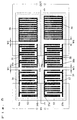
- FIG. 1 is an electrode pattern block diagram showing a first embodiment of a surface acoustic wave filter according to the present invention.
- an electrode pattern in stripline of a periodic structure enabling the excitation of a surface acoustic wave.
- a first filter track 12 On the piezoelectric substrate 11, are formed a first filter track 12 and a second filter track 13.
- the first filter track 12 is comprised of an input IDT 14, an output IDT 15, and a reflector 16.
- the second filter track13 is comprised of an input IDT 17, an output IDT 18, and a reflector 19.
- the distance W1 between the input IDT 14 and the output IDT 15 of the first filter track 12 is equal to the distance W3 between the input IDT 17 and the output IDT 18 of the second filter track 13. Assuming that the wavelength of the surface acoustic wave is ⁇ , the distance W2 between the output IDT 15 and the reflector 16 of the first filter track 12 differs from the distance W4 between the output IDT 18 and the reflector 19 of the second filter track 13 by n ⁇ + ⁇ /4 (n: natural number).
- the input IDTs 14 and 17 are single phase uni-directional transducers (SPUDTs). Further, the input IDT 14 and the input IDT 17 are electrically connected in phase with each other (that is, the arrangements of their respective electrode fingers are mutually equal), while the output IDT 15 and the output IDT 18 are electrically connected in opposite phase to each other (that is, the arrangements of their respective electrode fingers are displaced from each other), thus forming balanced type terminals, respectively.
- SPUDTs single phase uni-directional transducers
- electrode fingers are arranged in groups of two in a cycle of ⁇ at both of a positive electrode 15a and a negative electrode 15b, respectively.
- Each of the electrode fingers has a width along the propagation direction of surface acoustic wave of approximately ⁇ /8, while the center-to-center distance between the two electrode fingers of the one group is ⁇ /4.
- the space between adjacent, one pair of electrode fingers of the positive electrode 15a and one pair of electrode fingers of the negative electrode 15b is ⁇ /2. That is, the space H between the central point of the one pair of electrode fingers and the central point of the other pair of electrode fingers is ⁇ /2.
- an IDT configured in such a manner is referred to as double electrode.
- the output IDT 18 of the second filter track 13 also constitutes the double electrode. That is, in the IDT 18, electrode fingers are arranged in groups of two in a cycle of ⁇ at both of a positive electrode 18a and a negative electrode 18b, respectively. Each of the electrode fingers has a width along the propagation direction of surface acoustic wave of approximately ⁇ /8, while the center-to-center distance between the two electrode fingers of the one group is ⁇ /4. Further, the space between adjacent, one pair of electrode fingers of the positive electrode 18a and one pair of electrode fingers of the negative electrode 18b is ⁇ /2.
- the propagation path of a surface acoustic wave is considered in the embodiment 1 of the present invention shown in FIG. 1.
- the respective surface acoustic waves excited at the input IDTs 14 and 17 reach the output IDTs 15 and 18.
- these surface acoustic waves cannot be extracted as electric signal from the output IDTs 15 and 18 due to the fact that the electric phase difference between the output IDT 15 of the first filter track 12 and the output IDT 18 of the second filter track 13 is 180° .
- these surface acoustic waves pass through the output IDTs 15 and 18 to be reflected by the reflectors 16 and 19, respectively.
- the distance W2 and the distance W4 are mutually different, and hence the surface acoustic waves become 180° out of phase with each other.
- the electrical phase difference between the output IDT 15 of the first filter track 12 and the output IDT 18 of the second filter track 13 is 0° , and hence the out-of-phase surface acoustic waves can be extracted as output signal there.
- the surface acoustic wave propagation path is folded back by the use of the reflector, resulting in steep attenuation characteristics in the vicinity of the passband without an increase in number of electrode fingers of the input and output IDTs.
- the conventional surface acoustic wave filter shown in FIG. 15 the surface acoustic wave excited at the IDT 152 can be received at the output IDT 153 to be extracted as electric signal. Therefore, the number of electrode fingers of the input and output IDTs must be largely increased in order to obtain steep attenuation characteristics in the vicinity of the passband. Accordingly, the surface acoustic wave filter of this embodiment shown in FIG. 1 is largely reduced in filter size as compared with the prior art surface acoustic wave filter shown in FIG. 15.
- the output IDT 15 of the first filter track 12 and the output IDT 18 of the second filter track 13 are double electrodes. Accordingly, as shown in FIG. 2, the surface acoustic waves each reflected at the end face of its respective electrode finger have a phase difference of ⁇ /2 to be canceled, which enables the suppression of the internal reflection. Consequently, the surface acoustic waves propagated from the input IDTs 14 and 17 to the reflectors 16 and 19 are not disturbed at the output IDTs 15 and 18 to pass therethrough, which enables the implementation of filter characteristics being flat within the passband.
- the input IDT 14 of the first filter track 12 and the input IDT 17 of the second filter track 13 are uni-directional transducers such as single phase uni-directional transducer (SPUDT). Accordingly, the bi-directional loss at the input IDTs can be reduced to implement low-loss filter characteristics.
- SPUDT single phase uni-directional transducer
- the input IDT 14 of the first filter track 12 and the input IDT 17 of the second filter track 13 can properly be double electrodes each with an electrode finger width of ⁇ /8. In this case, the internal reflection can be suppressed to implement filter characteristics with broad and flat passband.
- the reflection coefficients of the reflectors 16 and 19 are set as roughly 1, which causes the surface acoustic waves reaching the reflectors 16 and 19 to totally reflect. This results in no leaking surface acoustic wave, enabling the implementation of low-loss filter characteristics.
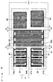
- FIG. 3 is a block diagram of an electrode pattern showing a second embodiment in accordance with the present invention.
- the difference from the embodiment 1 shown in FIG. 1 is in that on each of a reflector 36 of a first filter track 32 and a reflector 39 of a second filter track 33, weighting based on the width along the surface acoustic wave propagation direction of the electrode finger is performed. This enables the expansion of the degree of freedom of filter design. Alternatively, weighting based on the position of the electrode finger, and weighting based on the combination of the foregoing two terms can be carried out.
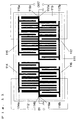
- FIG. 4 is a block diagram of an electrode pattern in which the reflector 36 of the first filter track 32 and the reflector 39 of the second filter track 33 are each comprised of at least two or more reflectors each having a different reflection characteristic.
- a reflector 46 of a first filter track 42 is comprised of reflector electrodes 46a, 46b, and 46c each having a different reflection characteristic
- a reflector electrode 49 of a second filter track 43 is comprised of reflectors 49a, 49b, and 49c each having a different reflection characteristic.
- the use of such a configuration enables the expansion of the degree of freedom of filter design, and hence the desired reflection characteristic can be obtained with ease.
- the input IDTs are electrically connected in phase with each other, while the output IDTs are electrically connected in opposite phase to each other.
- the same effects can be obtained.
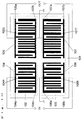
- FIG. 5 is a block diagram of an electrode pattern showing a third embodiment of the surface acoustic wave filter in accordance with the present invention.
- the difference from the embodiment 1 shown in FIG. 1 is as follows: in the embodiment 1, a connection is provided between the upper electrode 14a of the input IDT 14 of the first filter track 12 and the lower electrode 17b of the input IDT 17 of the second filter track 13 to form one of the balanced type input terminals. Meanwhile, a connection is provided between the lower electrode 14b of the input IDT 14 of the first filter track 12 and the upper electrode 17a of the input IDT 17 of the second filter track 13 to form the other of the balanced type input terminals. Thus, the balanced type input is implemented.
- the upper electrode 54a of an input IDT 54 of a first filter track 52 and the lower electrode 57b of an input IDT 57 of a second filter track 53 form balanced type input terminals. Meanwhile, the lower electrode 54b of the input IDT 54 of the first filter track 52 and the upper electrode 57a of the input IDT 57 of the second filter track 53 are grounded.
- the routing of wiring in the foregoing manner provides parallel to series connections of the cross capacities of the IDTs, which can raise the impedance of the filter without a reduction in cross width of the IDTs.
- an increase in impedance of the filter requires the cross capacity of the IDTs controlling the impedance of the filter to be reduced.
- This requires the cross width of the IDTs to be made small.
- the foregoing configuration enables an increase in impedance of the filter without reducing the cross width of the IDTs to implement filter characteristics with good attenuation characteristics on the high frequencies side.
- FIG. 8 is a block diagram of an electrode pattern showing a fourth embodiment of the surface acoustic wave filter in accordance with the present invention.
- a piezoelectric substrate 81 On a piezoelectric substrate 81, are formed a first filter track 82 and a second filter track 83.
- the first filter track 82 is comprised of an input IDT 84, a multi-strip coupler 85, and a reflector 86.
- the second filter track 83 is comprised of an input IDT 87, a multi-strip coupler 85, and a reflector 88.
- the input IDT 84 of the first filter track 82 and the input IDT 87 of the second filter track 83 have the same electrode configuration.
- the reflector electrode 86 of the first filter track 82 and the reflector electrode 88 of the second filter track 83 have the same electrode configuration.
- the distance W5 between the input IDT 84 and the multi-strip coupler 85 of the first filter track 82 is equal to the distance W7 between the input IDT 87 and the multi-strip coupler 85 of the second filter track 83.
- the distance W6 between the multi-strip coupler 85 and the reflector electrode 86 of the first filter track 82 differs from the distance W8 between the multi-strip coupler 85 and the reflector electrode 88 of the second filter track 83 by n ⁇ + ⁇ /4 (n: natural number).
- the input IDT 84 of the first filter track 82 and the input IDT 87 of the second filter track 83 are electrically connected in phase with each other to form balanced type input terminals, while the upper electrode 85a and the lower electrode 85b of the multi-strip coupler 85 form balanced type output terminals.
- both the positive electrode 85a and the negative electrode 85b are comprised of double electrodes, respectively. That is, in both the electrodes, electrode fingers are arranged in groups of two in a cycle of ⁇ . Each of the electrode fingers has a width along the surface acoustic wave propagation direction of approximately ⁇ /8, while the center-to-center distance between the two electrode fingers of the one group is ⁇ /4. Further, the space H between adjacent, one pair of electrode fingers of the positive electrode 85a and one pair of electrode fingers of the negative electrode 85b is ⁇ /2.
- the same filter characteristics as those in the embodiment 1 of the present invention of FIG. 1 can be implemented, and a routing electrode for an output terminal can be taken out easily, or the length of the routing electrode can be reduced, which enables a reduction in resistance loss. This results in the implementation of low-loss filter characteristics.
- FIG. 9 is a block diagram of an electrode pattern showing a fifth embodiment of the surface acoustic wave filter in accordance with the present invention.
- a piezoelectric substrate 91 On a piezoelectric substrate 91, are formed a first filter track 92 and a second filter track 93.
- the first filter track 92 and the second filter track 93 have a symmetrical construction with respect to the surface acoustic wave propagation direction as axial direction.
- the first filter track 92 is comprised of an input IDT 94 and an output IDT 95.
- the second filter track 93 is comprised of an input IDT 96 and an output IDT 97.
- a spacing of 10 ⁇ or more between the first filter track 92 and the second filter track 93 is preferably allowed. This ensures the prevention of mutual interference.
- the difference between this embodiment and the conventional surface acoustic wave filter shown in FIG. 15 is as follows: that is, the electrodes 152a and 152b each connected to the input terminal pair in the prior art example of FIG. 15 have mutually different electrode configurations, while, in this embodiment, the electrodes 94a and 96b each connected to the input terminal pair have the same electrode configuration. It is noted that the electrodes 94b and 96a also have the same electrode configuration. Similarly, the electrodes 95a and 97b each connected to the output terminal pair have the same electrode configuration. Also, 95b and 97a have the same electrode configuration.
- the electrodes each connected to the respective input and output terminal pairs have the same configuration, respectively.
- the balancing between terminals when the balanced type operation is effected is largely improved. This results in improvements in amount of attenuation outside the passband and insertion loss.
- the center frequency of the filter is fo, it is found to be fo ⁇ 5 MHz in the case of a filter having a passband of 1.3 MHz, thus it is improved by about 10 dB as compared with the prior art surface acoustic wave filter shown in FIG. 15.
- one electrode of the respective input and output IDTs is provided with dummy electrodes 944, 955, 966, and 977 at the portions from which IDT electrodes have been thinned out, respectively, in order to adjust the acoustic velocity of the surface acoustics waves.
- FIG. 9 illustrates such an electrode configuration that the dummy electrodes are provided at the lower electrodes 94b and 95b of the input and output IDT electrode pairs 94 and 95 of the first filter track 92 and the upper electrodes 96a and 97a of the input and output IDTs 96 and 97 of the second filter track 93.
- dummy electrodes are provided at the upper electrodes 94a and 95a of the input and output IDTs 94 and 95 of the first filter track 92 and the lower electrodes 96b and 97b of the input and output IDTs 96 and 97 of the second filter track 93.
- FIG. 10 is a block diagram of an electrode pattern in which the input and output IDTs 94, 95, 96, and 97 of the first filter track 92 and the second filter track 93 are single phase uni-directional transducers (SPUDTs) in the embodiment of the present invention of FIG. 9.
- the SPUDT electrode is a uni-directional electrode, and it is of an electrode configuration having a reflector in the inside of the IDT.
- reflector electrodes 1044, 1055, 1066, and 1077 are provided at the lower electrodes 104b and 105b of input and output IDTs 104 and 105 of a first filter track 102, and the upper electrodes 106a and 107a of input and output IDTs 106 and 107 of a second filter track 103, respectively.
- reflector electrodes are provided at the upper electrodes 104a and 105a of the input and output IDTs 104 and 105 of the first filter track 102, and the lower electrodes 106b and 107b of the input and output IDTs 106 and 107 of the second filter track 103.
- the connecting section between the IDT electrode 104b and the IDT electrode 106a, and the connecting section between the IDT electrode 105b and the IDT electrode 107a are connected to an earth.
- the resulting electrode configuration becomes less susceptible to the influences of the stray capacitance, and the like of the dummy electrodes and the reflector electrodes as compared with the latter case. This results in excellent characteristics in insertion loss and amount of attenuation outside the passband.
- FIG. 11 is a block diagram of an electrode pattern showing a sixth embodiment of the surface acoustic wave filter in accordance with the present invention.
- a first filter track 112 and a second filter track 113 are formed on a piezoelectric substrate 111.
- the first filter track 112 and the second filter track 113 have the construction as follows.
- the first filter track 112 is comprised of an input IDT 114 and an output IDT 114.
- the second filter track 113 is comprised of an input IDT 116 and an output IDT 117.
- the first filter track 112 is shifted in the surface acoustic wave propagation direction with respect to the second filter track 113 by an integral multiple of ⁇ /2 ( ⁇ : wavelength of the surface acoustic wave propagating on the piezoelectric substrate). Consequently, both the tracks form a symmetrical construction with respect to the surface acoustic wave propagation direction as axial direction.
- the two tracks having a symmetrical construction with respect to the surface acoustic wave propagation direction as axial direction are mutually shifted in the surface acoustic wave propagation direction by an integral multiple of ⁇ /2 ( ⁇ : wavelength of the surface acoustic wave propagating on the piezoelectric substrate), resulting in the construction of FIG. 11.
- connection between the lower electrode 114b of the input IDT 114 of the first filter track 112 and the upper electrode 116a of the input IDT 116 of the second track 113 to form a terminal, which is then connected to an earth.
- connection between the lower electrode 115b of the output IDT 115 of the first filter track 112 and the upper electrode 117a of the input IDT 117 of the second filter track 113 to form a terminal, which is then connected to an earth.
- the first filter track 112 and the second filter track 113 are arranged with being mutually shifted in the surface acoustic wave propagation direction by an integral multiple of ⁇ /2. Accordingly, the first filter track 112 and the second filter track 113 will not be acoustically influenced with each other. Therefore, it is unnecessary to ensure a sufficient distance between the first filter track 112 and the second filter track 113, and hence it becomes possible to implement a substantial downsizing of the device size.
- FIG. 12 is a block diagram of an electrode pattern showing a seventh embodiment of the surface acoustic wave filter in accordance with the present invention.
- a first filter track 122 and a second filter track 123 are formed on a piezoelectric substrate 121.
- the first filter track 122 and the second filter track 123 have the construction as follows.
- the first filter track 122 is comprised of an input IDT 124 which is a bi-directional electrode and an output IDT 124 which is a SPUDT electrode.
- the second filter track 123 is comprised of an input IDT 126 which is a bi-directional electrode, and an output IDT 127 which is a SPUDT electrode.
- the first filter track 122 is shifted in the surface acoustic wave propagation direction with respect to the second filter track 123 by an integral multiple of ⁇ /2. Consequently, both the tracks form a symmetrical construction with respect to the surface acoustic wave propagation direction as axial direction.
- the two tracks having a symmetrical construction with respect to the surface acoustic wave propagation direction as axial direction are mutually shifted in the surface acoustic wave propagation direction by an integral multiple of ⁇ /2 ( ⁇ : wavelength of the surface acoustic wave propagating on the piezoelectric substrate), resulting in the construction of FIG. 12.
- connection between the lower electrode 124b of the input IDT 124 of the first filter track 122 and the upper electrode 126a of the input IDT 126 of the second track 123 to form a terminal, which is then connected to an earth.
- connection between the lower electrode 125b of the output IDT 125 of the first filter track 122 and the upper electrode 127a of the input IDT 127 of the second filter track 123 to form a terminal, which is then connected to an earth.
- a filter for use in an IF stage of a digital mobile communication device is required to have flat in-passband characteristics, and hence it must be used in a state of impedance mismatching in order to suppress TTE, resulting in a very large insertion loss.
- the TTE level is very small in a state of impedance matching. This results in a filter with flat in-passband characteristics and low insertion loss. However, the amount of attenuation in the vicinity of the passband deteriorates for implementing a uni-directional property.
- the one electrode pair is of bi-directional electrodes, while the other is of SPUDT electrodes. This enables suppression of the TTE level in a state of impedance matching.
- this embodiment can implement a filter excellent in balancing to achieve improvements in amount of attenuation outside the passband and insertion loss.
- the above-described filter of the one-track configuration is assumed to be a balanced type filter in FIG. 14.
- the present invention can implement a small-sized and low-loss surface acoustic wave filter excellent in amount of attenuation in the vicinity of the passband.
- a piezoelectric substrate in the present invention it is preferable that a ST cut-quartz excellent in temperature characteristics is used.
- LiTaO3, LiNbO3, Li2B4O7, La3Ga5SiO14, and the like can be used as a substrate.
- electrode materials it is preferable to use aluminium of which the film thickness is easy to control, and having a relatively small density, however, a gold electrode can also be used.
- the communication device of the present invention is a communication device characterized by including the surface acoustic filter described above, a signal processing circuit for conducting a signal processing using the filter, a transmitter for transmitting the signals processed by the signal processing circuit, and a receiver for receiving an electronic radio wave.
Landscapes
- Physics & Mathematics (AREA)
- Acoustics & Sound (AREA)
- Surface Acoustic Wave Elements And Circuit Networks Thereof (AREA)
Applications Claiming Priority (4)
| Application Number | Priority Date | Filing Date | Title |
|---|---|---|---|
| JP35306797 | 1997-12-22 | ||
| JP35306797A JP3315913B2 (ja) | 1997-12-22 | 1997-12-22 | 弾性表面波フィルタ |
| JP517398 | 1998-01-13 | ||
| JP517398 | 1998-01-13 |
Publications (2)
| Publication Number | Publication Date |
|---|---|
| EP0924857A2 true EP0924857A2 (de) | 1999-06-23 |
| EP0924857A3 EP0924857A3 (de) | 2001-08-29 |
Family
ID=26339084
Family Applications (1)
| Application Number | Title | Priority Date | Filing Date |
|---|---|---|---|
| EP98124548A Withdrawn EP0924857A3 (de) | 1997-12-22 | 1998-12-22 | Akustisches Oberfächenwellenfilter |
Country Status (2)
| Country | Link |
|---|---|
| US (1) | US6104260A (de) |
| EP (1) | EP0924857A3 (de) |
Cited By (7)
| Publication number | Priority date | Publication date | Assignee | Title |
|---|---|---|---|---|
| DE19909470A1 (de) * | 1999-03-04 | 2000-09-21 | Dresden Ev Inst Festkoerper | Wandler für akustische Oberflächenwellen |
| EP1137176A2 (de) * | 2000-03-17 | 2001-09-26 | Fujitsu Media Devices Limited | Oberflächenwellenvorrichtung |
| DE10126036B4 (de) * | 2001-05-23 | 2004-02-26 | Leibniz-Institut für Festkörper- und Werkstoffforschung e.V. | Einphasen-Unidirektionalwandler |
| EP1221769A4 (de) * | 2000-06-30 | 2005-04-20 | Fujitsu Media Devices Ltd | Akustische oberflächenwellenanordnung |
| EP1443642A3 (de) * | 2003-01-24 | 2010-03-10 | Murata Manufacturing Co., Ltd. | Oberflächenwellenfilter und Kommunikationsvorrichtung |
| RU2457450C1 (ru) * | 2011-03-25 | 2012-07-27 | Открытое акционерное общество "Научно-производственное предприятие "Радар ммс" | Чувствительный элемент для измерения механических напряжений |
| EP2905616A4 (de) * | 2012-10-01 | 2015-12-16 | Panasonic Ip Man Co Ltd | Elastisches wellenelement und elastischer wellensensor damit |
Families Citing this family (27)
| Publication number | Priority date | Publication date | Assignee | Title |
|---|---|---|---|---|
| JP3487772B2 (ja) * | 1998-03-11 | 2004-01-19 | 富士通株式会社 | 弾性表面波フィルタ |
| KR20010034613A (ko) * | 1998-03-23 | 2001-04-25 | 에프코스 아게 | 표면파 음향 필터 |
| EP1104952B1 (de) * | 1999-05-14 | 2007-06-27 | Kabushiki Kaisha Toshiba | Oberflächenwellenfilter |
| KR20010072241A (ko) * | 1999-06-03 | 2001-07-31 | 모리시타 요이찌 | 탄성 표면파 필터 |
| CN1162968C (zh) * | 1999-10-04 | 2004-08-18 | 东芝株式会社 | 声表面波器件 |
| US6720842B2 (en) * | 2000-02-14 | 2004-04-13 | Murata Manufacturing Co., Ltd. | Surface acoustic wave filter device having first through third surface acoustic wave filter elements |
| JP3414373B2 (ja) * | 2000-07-26 | 2003-06-09 | 株式会社村田製作所 | 弾性表面波装置 |
| EP1189346B1 (de) * | 2000-09-13 | 2008-10-08 | Matsushita Electric Industrial Co., Ltd. | Akustisches Oberflächenwellenfilter und Kommunikationsvorrichtung mit demselben |
| JP3323860B2 (ja) * | 2000-10-31 | 2002-09-09 | 日本碍子株式会社 | 一方向性変換器及びそれを具える弾性表面波フィルタ装置 |
| JP3695353B2 (ja) * | 2000-11-17 | 2005-09-14 | 株式会社村田製作所 | トランスバーサル型弾性表面波フィルタ |
| US6815868B2 (en) * | 2001-04-09 | 2004-11-09 | Murata Manufacturing Co., Ltd. | Surface acoustic wave apparatus and communication unit |
| US6861927B1 (en) * | 2001-04-27 | 2005-03-01 | Sawtek, Inc. | Longitudinally coupled leaky surface acoustic wave resonator filter |
| US6798318B1 (en) | 2001-04-27 | 2004-09-28 | Sawtek, Inc. | Hybrid leaky surface acoustic wave resonator filter |
| US6806619B2 (en) * | 2001-10-16 | 2004-10-19 | Matsushita Electric Industrial Co., Ltd. | Interdigital transducer, surface acoustic wave filter, and radio communication apparatus |
| US6664871B2 (en) * | 2002-05-16 | 2003-12-16 | Northrop Grumman Corporation | Cascaded surface acoustic wave filter system for cancelling time spurious responses |
| JP2004040636A (ja) * | 2002-07-05 | 2004-02-05 | Murata Mfg Co Ltd | 表面波装置 |
| US6836197B2 (en) * | 2003-02-28 | 2004-12-28 | Northrop Grumman Corporation | Dual track SAW reflector filter using weighted reflective gratings |
| US6842091B2 (en) * | 2003-02-28 | 2005-01-11 | Northrop Grumman Corporation | Weighted SAW reflector grating using dithered acoustic reflectors |
| US6847272B2 (en) * | 2003-02-28 | 2005-01-25 | Northrop Grumman Corporation | Weighted SAW reflector using distributed acoustic reflective dots |
| JP4103666B2 (ja) * | 2003-04-03 | 2008-06-18 | 株式会社村田製作所 | 無線受信装置 |
| SG112100A1 (en) * | 2003-11-18 | 2005-06-29 | Fujitsu Media Devices Ltd | Surface acoustic device |
| JP4527968B2 (ja) * | 2003-11-26 | 2010-08-18 | 住友ゴム工業株式会社 | 空気入りタイヤ |
| US7653118B1 (en) | 2004-03-26 | 2010-01-26 | Cypress Semiconductor Corporation | Chirped surface acoustic wave (SAW) correlator/expander |
| DE102012107049B4 (de) * | 2012-08-01 | 2017-10-05 | Snaptrack, Inc. | Elektroakustischer Wandler |
| KR102331130B1 (ko) * | 2020-01-06 | 2021-11-26 | (주)와이솔 | 수신 필터회로 및 이것을 가진 공용기 |
| US12506464B2 (en) | 2021-12-06 | 2025-12-23 | Skyworks Solutions, Inc. | Multi-band surface acoustic wave filters |
| US12648470B2 (en) | 2022-03-30 | 2026-06-02 | Skyworks Solutions, Inc. | Package with integrated device die at least disposed within carrier |
Family Cites Families (17)
| Publication number | Priority date | Publication date | Assignee | Title |
|---|---|---|---|---|
| US3727155A (en) * | 1972-03-20 | 1973-04-10 | Zenith Radio Corp | Acoustic surface wave filter |
| US3946342A (en) * | 1973-08-10 | 1976-03-23 | Texas Instruments Incorporated | Weighting surface wave filters by withdrawing electrodes |
| GB1554366A (en) * | 1977-02-04 | 1979-10-17 | Philips Electronic Associated | Acoustic surface wave devices |
| JPS57119509A (en) * | 1981-01-19 | 1982-07-26 | Toshiba Corp | Surface acoustic wave resonator |
| DE3267639D1 (en) * | 1981-02-04 | 1986-01-09 | Matsushita Electric Industrial Co Ltd | Surface acoustic wave device |
| US5521565A (en) * | 1988-09-28 | 1996-05-28 | Siemens Aktiengesellschaft | Surface wave interdigital transducer and surface wave filter with symmetric or predeterminable asymmetric transfer characteristic between input and output |
| DE3942140A1 (de) * | 1989-12-20 | 1991-06-27 | Siemens Ag | Oberflaechenwellen-reflektorfilter |
| FR2658013B1 (fr) * | 1990-02-02 | 1992-04-17 | Thomson Csf | Filtre a ondes acoustiques de surface. |
| FR2682833B1 (fr) * | 1991-10-18 | 1993-12-03 | Thomson Csf | Filtre a ondes de surface et a trajet acoustique replie. |
| US5313177A (en) * | 1992-04-06 | 1994-05-17 | Motorola, Inc. | Method and apparatus for an acoustic wave filter |
| DE4214122C2 (de) * | 1992-04-29 | 2001-02-22 | Siemens Ag | Zweispur-Oberflächenwellenanordnung mit verbesserter Selektionseigenschaft |
| JP3606944B2 (ja) * | 1994-04-25 | 2005-01-05 | ノキア コーポレイション | Sawフィルタ |
| DE4419722C1 (de) * | 1994-06-06 | 1996-02-22 | Siemens Ag | Mit akustischen Oberflächenwellen arbeitendes Filter |
| US5663695A (en) * | 1994-10-31 | 1997-09-02 | Ngk Insulators, Ltd. | Surface acoustic wave filter device and transducer therefor |
| DE19548042C2 (de) * | 1995-12-21 | 1999-11-04 | Siemens Matsushita Components | Mit akustischen Oberflächenwellen arbeitendes Filter -OFW-Filter- |
| US5831494A (en) * | 1996-12-12 | 1998-11-03 | Sawtek Inc. | Dual track low-loss reflective saw filter |
| US5896071A (en) * | 1997-05-15 | 1999-04-20 | Northern Telecom Limited | Surface wave device balun resonator filters |
-
1998
- 1998-12-21 US US09/216,941 patent/US6104260A/en not_active Expired - Lifetime
- 1998-12-22 EP EP98124548A patent/EP0924857A3/de not_active Withdrawn
Cited By (9)
| Publication number | Priority date | Publication date | Assignee | Title |
|---|---|---|---|---|
| DE19909470A1 (de) * | 1999-03-04 | 2000-09-21 | Dresden Ev Inst Festkoerper | Wandler für akustische Oberflächenwellen |
| DE19909470C2 (de) * | 1999-03-04 | 2003-09-25 | Leibniz Inst Fuer Festkoerper | Wandler für akustische Oberflächenwellen |
| EP1137176A2 (de) * | 2000-03-17 | 2001-09-26 | Fujitsu Media Devices Limited | Oberflächenwellenvorrichtung |
| EP1221769A4 (de) * | 2000-06-30 | 2005-04-20 | Fujitsu Media Devices Ltd | Akustische oberflächenwellenanordnung |
| DE10126036B4 (de) * | 2001-05-23 | 2004-02-26 | Leibniz-Institut für Festkörper- und Werkstoffforschung e.V. | Einphasen-Unidirektionalwandler |
| EP1443642A3 (de) * | 2003-01-24 | 2010-03-10 | Murata Manufacturing Co., Ltd. | Oberflächenwellenfilter und Kommunikationsvorrichtung |
| RU2457450C1 (ru) * | 2011-03-25 | 2012-07-27 | Открытое акционерное общество "Научно-производственное предприятие "Радар ммс" | Чувствительный элемент для измерения механических напряжений |
| EP2905616A4 (de) * | 2012-10-01 | 2015-12-16 | Panasonic Ip Man Co Ltd | Elastisches wellenelement und elastischer wellensensor damit |
| US9518863B2 (en) | 2012-10-01 | 2016-12-13 | Panasonic Intellectual Property Management Co., Ltd. | Elastic wave element and elastic wave sensor using same |
Also Published As
| Publication number | Publication date |
|---|---|
| EP0924857A3 (de) | 2001-08-29 |
| US6104260A (en) | 2000-08-15 |
Similar Documents
| Publication | Publication Date | Title |
|---|---|---|
| US6104260A (en) | Surface acoustic wave filter with first and second filter tracks and balanced or unbalanced terminals | |
| US5721519A (en) | Balanced type surface acoustic wave device | |
| EP0897218B1 (de) | Akustische Oberflächenwellenfilter | |
| US6346864B1 (en) | Saw resonator filter and duplexer utilizing SH waves, substrate edge reflection, and sub-interdigital transducer portions | |
| EP0871288B1 (de) | Akustische Oberflächenwellenanordnung | |
| US7532090B2 (en) | Acoustic wave filter device and duplexer | |
| EP1263137B1 (de) | Akustisches Oberflächenwellenfilter, symmetrisches Filter und Kommunikationsgerät | |
| JPH08265087A (ja) | 弾性表面波フィルタ | |
| EP1251638A2 (de) | Akustische Oberflächenwellenfiltervorrichtung und Kommunikationseinrichtung | |
| EP2254244B1 (de) | Symmetrierfilter und Duplexer | |
| US6326864B1 (en) | Surface acoustic wave filter, duplexer and communications device with specific series resonator multiple anti-resonant point placement | |
| JP4541853B2 (ja) | アンテナ分波器およびアンテナ分波器用表面弾性波フィルタ | |
| KR20020003077A (ko) | 탄성표면파 장치 | |
| EP0981857B1 (de) | Oberflächenwellen balun resonatorfilter | |
| US6462633B1 (en) | Surface acoustic wave device including parallel connected main and sub-filters | |
| US7429905B2 (en) | Balanced acoustic wave filter | |
| JP3757893B2 (ja) | 弾性表面波装置、および、これを搭載した通信装置 | |
| JP3315913B2 (ja) | 弾性表面波フィルタ | |
| JP3514015B2 (ja) | 弾性表面波装置及びその製造方法 | |
| US6310524B1 (en) | Edge reflection type longitudinally coupled saw resonator filter | |
| JPH11266138A (ja) | 弾性表面波フィルタ | |
| JPH10261936A (ja) | 弾性表面波フィルタ | |
| JP3224455B2 (ja) | 弾性表面波素子 | |
| JPH10270981A (ja) | 弾性表面波フィルタ | |
| JP2004128928A (ja) | 弾性表面波フィルタ装置、通信装置 |
Legal Events
| Date | Code | Title | Description |
|---|---|---|---|
| PUAI | Public reference made under article 153(3) epc to a published international application that has entered the european phase |
Free format text: ORIGINAL CODE: 0009012 |
|
| AK | Designated contracting states |
Kind code of ref document: A2 Designated state(s): AT BE CH CY DE DK ES FI FR GB GR IE IT LI LU MC NL PT SE |
|
| AX | Request for extension of the european patent |
Free format text: AL;LT;LV;MK;RO;SI |
|
| PUAL | Search report despatched |
Free format text: ORIGINAL CODE: 0009013 |
|
| AK | Designated contracting states |
Kind code of ref document: A3 Designated state(s): AT BE CH CY DE DK ES FI FR GB GR IE IT LI LU MC NL PT SE |
|
| AX | Request for extension of the european patent |
Free format text: AL;LT;LV;MK;RO;SI |
|
| 17P | Request for examination filed |
Effective date: 20011001 |
|
| AKX | Designation fees paid |
Free format text: DE FR GB |
|
| 17Q | First examination report despatched |
Effective date: 20050215 |
|
| 17Q | First examination report despatched |
Effective date: 20050215 |
|
| STAA | Information on the status of an ep patent application or granted ep patent |
Free format text: STATUS: THE APPLICATION IS DEEMED TO BE WITHDRAWN |
|
| 18D | Application deemed to be withdrawn |
Effective date: 20070109 |