EP0924877A2 - Méthode de filtrage et de démodulation de sources indépendentes FDMA - Google Patents
Méthode de filtrage et de démodulation de sources indépendentes FDMA Download PDFInfo
- Publication number
- EP0924877A2 EP0924877A2 EP98123470A EP98123470A EP0924877A2 EP 0924877 A2 EP0924877 A2 EP 0924877A2 EP 98123470 A EP98123470 A EP 98123470A EP 98123470 A EP98123470 A EP 98123470A EP 0924877 A2 EP0924877 A2 EP 0924877A2
- Authority
- EP
- European Patent Office
- Prior art keywords
- satellite
- cpe
- ofdm
- timing
- uplink signal
- Prior art date
- Legal status (The legal status is an assumption and is not a legal conclusion. Google has not performed a legal analysis and makes no representation as to the accuracy of the status listed.)
- Withdrawn
Links
Images

Classifications
-
- H—ELECTRICITY
- H04—ELECTRIC COMMUNICATION TECHNIQUE
- H04B—TRANSMISSION
- H04B7/00—Radio transmission systems, i.e. using radiation field
- H04B7/14—Relay systems
- H04B7/15—Active relay systems
- H04B7/204—Multiple access
- H04B7/208—Frequency-division multiple access [FDMA]
-
- H—ELECTRICITY
- H04—ELECTRIC COMMUNICATION TECHNIQUE
- H04L—TRANSMISSION OF DIGITAL INFORMATION, e.g. TELEGRAPHIC COMMUNICATION
- H04L5/00—Arrangements affording multiple use of the transmission path
- H04L5/02—Channels characterised by the type of signal
- H04L5/023—Multiplexing of multicarrier modulation signals, e.g. multi-user orthogonal frequency division multiple access [OFDMA]
Definitions
- the present invention relates to satellite communications systems. More specifically, the invention relates to a method of synchronizing received uplink signals at a satellite such that bulk signal processing may be used to simultaneously recover multiple data channels in the uplink signals.
- Modern communications networks carry staggering amounts of information, typically divided for transmission purposes into individual data channels. Whether the data channels carried by the communications network have their origin in the telephone system, television stations, or other source, these data channels often need to be transmitted through a communications network including a satellite link.
- CPE Customer Premises Equipment
- Multiple uplink signals may be generated by multiple CPEs, with each uplink signal carrying one or more data channels. Because many CPEs may communicate with a single satellite, the potential number of data channels that a single satellite may need to process can grow very large.
- FDMA frequency division multiple access
- channels narrow frequency subbands
- ACI adjacent channel interference
- each data channel present in an FDMA uplink signal is received and demodulated on an individual basis.
- a very efficient bulk demodulation scheme can be implemented at the satellite to receive and demodulate all the channels in the uplink signal in a single operation.
- Bulk demodulation requires time signaling synchronization among all the CPEs transmitting uplink signals.
- satellites and CPEs have been unable to achieve synchronization among the individual CPEs.
- the channels can be spaced such that their frequency responses are orthogonal (thereby giving rise to the name orthogonal frequency division multiplexing (OFDM)).
- OFDM orthogonal frequency division multiplexing
- the frequency responses can be overlapping, and with proper processing, be free of ACI. The result is very efficient bandwidth utilization.
- the satellite communications technique of the present invention synchronizes the reception of numerous CPE-transmitted OFDM uplink signals at the satellite receiver. Because the OFDM uplink signals are synchronized correctly, the satellite may bulk process the data channels in the OFDM uplink signals. In other words, the individual data channels in the OFDM uplink signals may be processed without the need for individual processing electronics for each data channel.
- the satellite receives an OFDM uplink signal transmitted by a CPE.
- the satellite compares the reception timing of the received OFDM uplink signal with a satellite timing reference and generates a timing correction.
- the satellite provides a downlink symbol clock in a downlink beam to the CPE and further transmits the timing correction in the downlink beam.
- the CPE During reception, the CPE synchronizes to the downlink beam and extracts the inherent downlink symbol clock. The CPE uses the downlink symbol clock in conjunction with the timing correction to generate an uplink clock. The CPE then uses the uplink clock to synchronously pass uplink data to CPE transmitter circuitry.
- the satellite may synchronize each OFDM uplink signal transmitted by each CPE.
- the net result is individual OFDM uplink signals arriving at the satellite with synchronization that makes the individual OFDM uplink signals appear to the satellite as a single composite OFDM uplink signal that has a bandwidth spanning the individual OFDM uplink signals.
- the single composite OFDM uplink signal may then be processed in bulk in the satellite.
- the satellite may also periodically re-compare the reception timing of the OFDM uplink signals with the satellite timing reference to generate new timing corrections, if necessary, for the CPEs. In this manner, the satellite may keep the OFDM uplink signals in synchronization and achieve the benefits of bulk processing indefinitely.
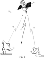
- FIG 1 that figure illustrates a communications network 100 including a first CPE 102, a second CPE 104, and a satellite 106.
- the first CPE 102 transmits a first OFDM uplink signal 108 to the satellite 106
- the second CPE 104 transmits a second OFDM uplink signal 110 to the satellite 106.
- the satellite 106 communicates in part with the first CPE 102 and second CPE 104 through the downlink beam 112.
- each OFDM uplink signal 108, 110 is divided into a number of subcarriers containing the actual data channels. Furthermore, since there may be additional CPEs (not shown) transmitting OFDM uplink signals to the satellite 106, a large quantity of data channels may arrive for processing at the satellite 106 asynchronously. Because techniques are available for efficiently processing the data channels in an OFDM uplink signal, the present invention uses the satellite 106 to adjust the timing of the individual OFDM uplink signals 108,110 such that the satellite 106 can treat the individual uplink OFDM signals 108,110 as a single composite OFDM uplink signal for processing purposes. In other words, after the satellite adjusts the timing of the individual uplink OFDM signals 108, 110, the satellite may treat the individual uplink OFDM signals 108, 110 as the equivalent of a single composite uplink signal.
- the CPE 104 may begin service by locking onto and demodulating the downlink beam 112 in order to generate an initial uplink clock that controls the timing of the uplink signal 110.
- satellite 106 provides the structure in the downlink beam 112 that allows the CPE 104 to lock onto the downlink beam 112.
- Figure 2 a block diagram of the satellite 106 is shown that illustrates the transmitter, internal synchronization, and processing hardware in the satellite 106.
- the satellite 106 receiver provides received signals, including the OFDM uplink signal 110 signal, for processing on an uplink RF receiver output 200 which is connected to a Wideband analog to digital (A/D) converter 202.
- the satellite 106 also includes an input buffer 204, Window and Pre-sum block 206, and a Fast Fourier Transform (FFT) processor 208.
- FFT Fast Fourier Transform
- the satellite 106 further includes a calibration demodulator 210, control processor 212, time and frequency generator 214, and a data formatter and downlink multiplexer 216.
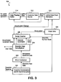
- FIG 3 a block diagram representative of the CPE 104 is shown.
- the CPE 104 includes a downlink demodulation and bit synchronizer 300, error correction unit 302, and a downlink data demultiplexer 304.
- the CPE 104 further includes "Bump" counter 306, clock gate 308, and an uplink clock generator 310.
- the CPE 104 is able to accept customer data from a customer data source 312 and synchronize the customer data with the data phasing buffer 314.
- the CPE 104 structure shown in Figure 3 operates in conjunction with the satellite 106 to establish communication and synchronization with the satellite 106.
- the time and frequency generator 214 produces the internal reference clocks used in the satellite 106.
- the time and frequency generator 214 generates a downlink clock that is connected to the data formatter and downlink multiplexer 216.
- the data formatter and downlink multiplexer 216 uses the downlink clock to time the production of data streams that will be transmitted in the downlink beam 112.
- the downlink beam 112 contains, as inherent structure, a downlink symbol clock represented by the modulated transmitted data forming the downlink beam 112.
- the CPE 104 To establish service with the satellite 106, the CPE 104 first locks onto and demodulates the downlink beam 112 using the downlink demodulator and bit synchronizer 300 ( Figure 3). Because the downlink symbol clock is inherent in the downlink beam 112, the downlink demodulator and bit synchronizer 300 may recover the downlink symbol clock and provide it to the clock gate 308.
- the clock gate 308 determines when the downlink symbol clock is allowed to drive the uplink data clock generator 310. When establishing service with the satellite 106, the clock gate 308 may allow the downlink symbol clock to drive the uplink clock generator 310 continuously so that the CPE can generate an initial uplink clock.
- the uplink clock generator 310 synthesizes an uplink clock from the downlink symbol clock.
- a variety of techniques may be used to generate the uplink clock, including using a numerically controlled oscillator (NCO) or a digital direct frequency synthesizer (DDFS) that uses the downlink symbol clock as a reference.
- NCO numerically controlled oscillator
- DDFS digital direct frequency synthesizer
- the downlink symbol clock provided by the satellite 106 runs at a frequency 10 times or more higher than the uplink clock that the uplink clock generator 310 will synthesize.
- An initial frequency for the uplink clock may be established, for example, by storing a predetermined increment value in the NCO accumulator.
- the CPE 104 may then request service through the satellite 106 by transmitting a synchronization request to the satellite 106.
- the CPE 104 may use the OFDM uplink signal 110 to send the synchronization request to the satellite 106.
- the CPE 104 transmits the synchronization request at a rate which is a submultiple of the uplink clock rate that the CPE 104 uses.
- the synchronization request preferably includes a CPE 104 identifier, such as a unique number, string, or location.
- the satellite 106 processes the synchronization request and provides the CPE 104 with synchronization information.
- Information in the OFDM uplink signal 110 may be processed starting at the uplink RF receiver output 200.
- the uplink RF receiver output 200 connects to the Wideband A/D converter 202 which converts the OFDM uplink signal present on the uplink RF receiver output 200 into digital samples.
- the calibration demodulator 210 analyzes the digital samples and detects the presence of the synchronization request.
- the time and frequency generator 214 provides a spacecraft symbol time reference to the calibration demodulator 212.
- the calibration demodulator 212 may, therefore, determine the relative time of arrival between the OFDM uplink signal 110 carrying the synchronization request and the spacecraft symbol time reference.
- the calibration demodulator 210 operates at ten to twelve times the digital sample rate in order to provide timing measurement accuracy in the symbols that make up the uplink data channel of under 1% of the symbol duration and uplink signal 110 frequency measurement inaccuracy of under 5% of the symbol rate.
- the calibration demodulator 210 forwards the relative time of arrival to the control processor 212.
- the control processor 212 determines the timing correction needed to place the uplink signal 110 at the optimum time position for bulk processing of the OFDM uplink signal 110.
- the control processor 212 determines the timing correction for the CPE 104 such that the symbols in the data channels in the OFDM uplink signal 110 arrive at the satellite in synchronization with other OFDM uplink signals.
- the individual OFDM uplink signals appear to the satellite 106 as a single composite OFDM uplink signal that has a bandwidth spanning the individual OFDM uplink signals.
- the OFDM uplink signal timing is phased so that each symbol interval in each data channel in each OFDM uplink signal spans each FFT processor 208 input data block.
- the control processor 212 After the control processor 212 has determined the necessary timing correction for the uplink signal 110, the control processor 212 forwards the timing correction along with the corresponding CPE 104 identifier to the data formatter and downlink multiplexer 216.
- the data formatter and downlink multiplexer 216 inserts the timing correction and CPE 104 identifier into the downlink data stream along with any additional user data destined for the CPE 104.
- the satellite 106 then transmits the resultant multiplexed raw data comprising the downlink data stream in the downlink beam 112 for processing in the CPE 104.
- the downlink demodulator and bit synchronizer 300 extracts the raw data destined for the CPE 104 from the downlink beam 112.
- the raw data undergoes error correction controlled by the error correction unit 302 in conjunction with any predetermined error correcting codes (for example, parity codes, Hamming codes, block codes, or convolutional codes) that the satellite may have used.
- the output of the error correction unit 302 consists of downlink data which is multiplexed between user data and timing correction information.
- the downlink data demultiplexer 304 separates the user data from the timing correction and forwards the timing correction to the bump counter 306.
- the timing correction represents the number of downlink symbol clock periods for which the downlink symbol clock should be disabled.
- the bump counter 306 produces a clock inhibit signal which causes the clock gate 308 to disconnect the downlink symbol clock from the uplink data clock generator 310 (thereby delaying, phase shifting, and correcting the uplink clock generated by the uplink data clock generator 310).
- the bump counter 306 releases the clock inhibit signal when the bump counter 306 has detected that the number of downlink symbol clock periods indicated by the timing correction has passed.
- the bump counter 306 may operate whenever the timing correction is non-zero, or, in an alternative embodiment, the satellite 106 may provide an explicit execute command in addition to the timing correction to start the operation of the bump counter 306.
- the satellite 106 provides a new accumulator increment value for an NCO operating as the uplink data clock generator 310.
- the bump counter 306 may then assert the new accumulator increment value to the uplink data clock generator 310.
- the new accumulator increment value may be set as permanent change in the uplink data clock generator 310.
- the satellite 106 may also provide a count value representing the number of downlink symbol clocks after which the bump counter 306 de-asserts the new accumulator increment value (thereby allowing the uplink data clock generator 310 to revert to its previous accumulator increment value). It is noted that the timing correction schemes discussed above may be used with one another, or with any other timing correction method (such as controlling the voltage on a voltage controlled oscillator).
- the CPE 104 may begin regular OFDM uplink signal transmissions to the satellite 106. Note that the CPE 104 may provide the uplink clock to the customer data source 312 to help ensure synchronization. Because the user data source may contain delays that the CPE 104 cannot account for, however, the customer data source 312 may be connected to a data phasing buffer 314.
- the data phasing buffer 314 is connected to the CPE 104 transmitter, the uplink clock, and the customer data source 312. Customer data produced by the customer data source 312 may thereby be buffered in the data phasing buffer 314. The data phasing buffer 314 then stores the customer data and provides the customer data to the CPE transmitter with the uplink clock to maintain the proper synchronization.
- the satellite 106 may treat all the OFDM uplink signals arriving at the satellite as a single composite OFDM uplink signal. In other words, the satellite 106 may bulk process the composite OFDM uplink signal.
- the satellite 106 employs the Wideband A/D converter 202 to generate signal samples representative of the composite OFDM uplink signal arriving at the satellite 106.
- the signal samples are then operated on in bulk by an FFT process.
- the FFT process optionally includes the pre-processing steps of synchronously buffering the digital samples with the spacecraft symbol time reference in the input buffer 204, as well as windowing and pre-summing the digital samples for more efficient processing by the FFT processor 208.
- the FFT processor 208 produces signals representative of the data channels carried in the composite uplink signal. Because the symbols in the data channels making up the OFDM uplink signals are synchronized with the FFT processor 208 input data block, the FFT processor 208 also functions as a predetection matched filter at the uplink symbol rate. In one embodiment of the present invention, the FFT processor 208 is configured to generate channel I-Q pairs that represent the Quadrature Phase Shift Keying (QPSK) modulation of the data channels. If differential detection is used, each channel may be demodulated by performing a complex multiplication between the current I-Q pairs and the complex conjugate of the previous I-Q pairs. The FFT processor 208 outputs data for each channel at the uplink symbol rate. Furthermore, the FFT processor 208 may continue to operate indefinitely because the satellite 106 periodically checks the synchronization of each OFDM uplink signal.
- QPSK Quadrature Phase Shift Keying
- the satellite 106 may periodically re-compare the reception timing of the OFDM uplink signal 104 with the spacecraft symbol timing reference to generate new timing corrections for the CPE 104.
- the satellite 106 may re-compare the reception timing on a fixed basis, for example every 10 or 20 minutes, or on command, for example, from a ground station. In this manner, the satellite 106 may keep the OFDM uplink signal 110 in synchronization and achieve the benefits of bulk processing indefinitely.
Landscapes
- Engineering & Computer Science (AREA)
- Signal Processing (AREA)
- Computer Networks & Wireless Communication (AREA)
- Radio Relay Systems (AREA)
Applications Claiming Priority (2)
| Application Number | Priority Date | Filing Date | Title |
|---|---|---|---|
| US08/995,327 US6064645A (en) | 1997-12-22 | 1997-12-22 | Bulk filtering and demodulation of independent FDMA sources |
| US995327 | 1997-12-22 |
Publications (2)
| Publication Number | Publication Date |
|---|---|
| EP0924877A2 true EP0924877A2 (fr) | 1999-06-23 |
| EP0924877A3 EP0924877A3 (fr) | 2003-02-05 |
Family
ID=25541664
Family Applications (1)
| Application Number | Title | Priority Date | Filing Date |
|---|---|---|---|
| EP98123470A Withdrawn EP0924877A3 (fr) | 1997-12-22 | 1998-12-11 | Méthode de filtrage et de démodulation de sources indépendentes FDMA |
Country Status (2)
| Country | Link |
|---|---|
| US (1) | US6064645A (fr) |
| EP (1) | EP0924877A3 (fr) |
Cited By (2)
| Publication number | Priority date | Publication date | Assignee | Title |
|---|---|---|---|---|
| WO2002028002A3 (fr) * | 2000-09-27 | 2003-01-16 | Spacenet Inc | Systeme a satellite bidirectionnel de multiplexage orthogonal a repartition en frequence |
| US7626920B2 (en) | 1999-10-22 | 2009-12-01 | Nextnet Wireless, Inc. | Fixed OFDM wireless MAN utilizing CPE having internal antenna |
Families Citing this family (6)
| Publication number | Priority date | Publication date | Assignee | Title |
|---|---|---|---|---|
| US6643281B1 (en) * | 1998-03-05 | 2003-11-04 | At&T Wireless Services, Inc. | Synchronization preamble method for OFDM waveforms in a communications system |
| US7593724B2 (en) * | 2001-09-14 | 2009-09-22 | Atc Technologies, Llc | Systems and methods for terrestrial reuse of cellular satellite frequency spectrum in a time-division duplex mode |
| US7792069B2 (en) | 2001-09-14 | 2010-09-07 | Atc Technologies, Llc | Systems and methods for terrestrial reuse of cellular satellite frequency spectrum using different channel separation technologies in forward and reverse links |
| US7664460B2 (en) * | 2001-09-14 | 2010-02-16 | Atc Technologies, Llc | Systems and methods for terrestrial reuse of cellular satellite frequency spectrum in a time-division duplex and/or frequency-division duplex mode |
| FR3092455B1 (fr) * | 2019-01-31 | 2021-08-06 | Thales Sa | Systeme de communication par satellite a demodulation distribuee |
| DE102019209968A1 (de) * | 2019-07-06 | 2021-01-07 | Robert Bosch Gmbh | OFDM-Radarsensor mit mehreren Sendekanälen und fortschreitender Berechnung von Zeitsignalen |
Family Cites Families (14)
| Publication number | Priority date | Publication date | Assignee | Title |
|---|---|---|---|---|
| US4715029A (en) * | 1986-07-02 | 1987-12-22 | Hughes Aircraft Company | FDMA communications channel synchronizer |
| US4719619A (en) * | 1986-07-03 | 1988-01-12 | Hughes Aircraft Company | Synchronizer for communications processor |
| JPS6471329A (en) * | 1987-09-11 | 1989-03-16 | Nec Corp | Mobile body satellite communication system |
| JPS6488273A (en) * | 1987-09-30 | 1989-04-03 | Nec Corp | Communication/position-measurement system of moving body by satellites |
| JPH0746217A (ja) * | 1993-07-26 | 1995-02-14 | Sony Corp | ディジタル復調装置 |
| JPH0746218A (ja) * | 1993-07-28 | 1995-02-14 | Sony Corp | ディジタル復調装置 |
| US5444697A (en) * | 1993-08-11 | 1995-08-22 | The University Of British Columbia | Method and apparatus for frame synchronization in mobile OFDM data communication |
| JP3521016B2 (ja) * | 1995-03-27 | 2004-04-19 | 松下電器産業株式会社 | 直交周波数分割多重信号の受信方法および受信装置 |
| SE515752C2 (sv) * | 1995-08-28 | 2001-10-08 | Telia Ab | Direktåtkomst i OFDM-system |
| GB9521739D0 (en) * | 1995-10-24 | 1996-01-03 | Nat Transcommunications Ltd | Decoding carriers encoded using orthogonal frequency division multiplexing |
| JPH09130362A (ja) * | 1995-10-30 | 1997-05-16 | Sony Corp | 受信装置および受信方法 |
| JP2875976B2 (ja) * | 1996-01-29 | 1999-03-31 | 三星電子株式会社 | 直交周波数分割多重の方法及び同期方法と、直交周波数分割多重用変調器及び復調器 |
| US5914933A (en) * | 1996-03-08 | 1999-06-22 | Lucent Technologies Inc. | Clustered OFDM communication system |
| US5867478A (en) * | 1997-06-20 | 1999-02-02 | Motorola, Inc. | Synchronous coherent orthogonal frequency division multiplexing system, method, software and device |
-
1997
- 1997-12-22 US US08/995,327 patent/US6064645A/en not_active Expired - Lifetime
-
1998
- 1998-12-11 EP EP98123470A patent/EP0924877A3/fr not_active Withdrawn
Cited By (4)
| Publication number | Priority date | Publication date | Assignee | Title |
|---|---|---|---|---|
| US7626920B2 (en) | 1999-10-22 | 2009-12-01 | Nextnet Wireless, Inc. | Fixed OFDM wireless MAN utilizing CPE having internal antenna |
| CN1758621B (zh) * | 1999-10-22 | 2012-12-05 | 耐克斯特奈特无线公司 | 无线通信系统中的自动计算机房屋设备登记 |
| CN1758618B (zh) * | 1999-10-22 | 2012-12-05 | 耐克斯特奈特无线公司 | 利用下行链路和上行链路的数据分组传送系统和方法 |
| WO2002028002A3 (fr) * | 2000-09-27 | 2003-01-16 | Spacenet Inc | Systeme a satellite bidirectionnel de multiplexage orthogonal a repartition en frequence |
Also Published As
| Publication number | Publication date |
|---|---|
| EP0924877A3 (fr) | 2003-02-05 |
| US6064645A (en) | 2000-05-16 |
Similar Documents
| Publication | Publication Date | Title |
|---|---|---|
| AU605447B2 (en) | Earth station capable of effectively using a frequency band of a satellite | |
| US4599732A (en) | Technique for acquiring timing and frequency synchronization for modem utilizing known (non-data) symbols as part of their normal transmitted data format | |
| US4470141A (en) | Multi-direction time division multiplex communication system | |
| AU604206B2 (en) | Mobile satellite communication system | |
| US5790784A (en) | Network for time synchronizing a digital information processing system with received digital information | |
| AU710269B2 (en) | Doubly orthogonal code and frequency division multiple access communication system | |
| US6128357A (en) | Data receiver having variable rate symbol timing recovery with non-synchronized sampling | |
| US4783779A (en) | Frequency assignment system in FDMA communication system | |
| JPH1075203A (ja) | 衛星をベースとするテレコミュニケーションシステムにおいて通信を同期する方法及び装置 | |
| CA2367978A1 (fr) | Reseau de multiples recepteurs mrof en amont | |
| WO1998035455A1 (fr) | Procede de synchronisation d'une station distante avec une station de base dans un systeme de communication multi-tonalites discretes a spectre etale | |
| US7277493B2 (en) | Equalization in orthogonal frequency domain multiplexing | |
| US7042854B2 (en) | Method and apparatus for acquiring a synchronization signal | |
| JPH0795758B2 (ja) | 復調器 | |
| US6064645A (en) | Bulk filtering and demodulation of independent FDMA sources | |
| US5259005A (en) | Apparatus for and method of synchronizing a clock signal | |
| US9059780B1 (en) | Device and method for nodal multiple access into communications channels | |
| TW448646B (en) | Method and apparatus for precorrecting timing and frequency in communication systems | |
| US4754449A (en) | Wide bandwidth device for demodulating frequency division multiplexed signals | |
| JPH09252278A (ja) | 無線同報通信システム | |
| HK18797A (en) | TDMA communications system with adaptive equalization | |
| US4591730A (en) | Master clock generator for telecommunications system | |
| KR100965192B1 (ko) | 여러 무선 단말기들을 위한 빠른 타이밍 포착 | |
| Hui et al. | A fast and high-precision satellite-ground synchronization technology in satellite beam hopping communication | |
| MXPA04011778A (es) | Metodo y aparato para habilitar la transmision de una senal inalambrica de un canal de regreso en un sistema de comunicaciones por satelite. |
Legal Events
| Date | Code | Title | Description |
|---|---|---|---|
| PUAI | Public reference made under article 153(3) epc to a published international application that has entered the european phase |
Free format text: ORIGINAL CODE: 0009012 |
|
| AK | Designated contracting states |
Kind code of ref document: A2 Designated state(s): AT BE CH CY DE DK ES FI FR GB GR IE IT LI LU MC NL PT SE |
|
| AX | Request for extension of the european patent |
Free format text: AL;LT;LV;MK;RO;SI |
|
| RIC1 | Information provided on ipc code assigned before grant |
Free format text: 7H 04B 7/208 A, 7H 04B 7/185 B |
|
| PUAL | Search report despatched |
Free format text: ORIGINAL CODE: 0009013 |
|
| AK | Designated contracting states |
Designated state(s): AT BE CH CY DE DK ES FI FR GB GR IE IT LI LU MC NL PT SE |
|
| AX | Request for extension of the european patent |
Extension state: AL LT LV MK RO SI |
|
| 17P | Request for examination filed |
Effective date: 20030314 |
|
| 17Q | First examination report despatched |
Effective date: 20030522 |
|
| AKX | Designation fees paid |
Designated state(s): DE FR GB IT |
|
| RAP1 | Party data changed (applicant data changed or rights of an application transferred) |
Owner name: NORTHROP GRUMMAN CORPORATION |
|
| RAP1 | Party data changed (applicant data changed or rights of an application transferred) |
Owner name: NORTHROP GRUMMAN CORPORATION |
|
| GRAP | Despatch of communication of intention to grant a patent |
Free format text: ORIGINAL CODE: EPIDOSNIGR1 |
|
| GRAS | Grant fee paid |
Free format text: ORIGINAL CODE: EPIDOSNIGR3 |
|
| STAA | Information on the status of an ep patent application or granted ep patent |
Free format text: STATUS: THE APPLICATION IS DEEMED TO BE WITHDRAWN |
|
| 18D | Application deemed to be withdrawn |
Effective date: 20050701 |