EP0925950A2 - Appareil d'enregistrement et sa méthode de commande - Google Patents
Appareil d'enregistrement et sa méthode de commande Download PDFInfo
- Publication number
- EP0925950A2 EP0925950A2 EP98310668A EP98310668A EP0925950A2 EP 0925950 A2 EP0925950 A2 EP 0925950A2 EP 98310668 A EP98310668 A EP 98310668A EP 98310668 A EP98310668 A EP 98310668A EP 0925950 A2 EP0925950 A2 EP 0925950A2
- Authority
- EP
- European Patent Office
- Prior art keywords
- recording
- pitch
- conveying
- recording medium
- integer
- Prior art date
- Legal status (The legal status is an assumption and is not a legal conclusion. Google has not performed a legal analysis and makes no representation as to the accuracy of the status listed.)
- Granted
Links
- 238000000034 method Methods 0.000 title claims description 14
- 239000000976 ink Substances 0.000 claims description 68
- 238000007599 discharging Methods 0.000 claims description 19
- 230000015572 biosynthetic process Effects 0.000 description 13
- 238000010276 construction Methods 0.000 description 10
- 239000007788 liquid Substances 0.000 description 10
- 230000009467 reduction Effects 0.000 description 9
- 230000006870 function Effects 0.000 description 6
- 230000007246 mechanism Effects 0.000 description 5
- 238000010438 heat treatment Methods 0.000 description 4
- 238000009835 boiling Methods 0.000 description 3
- 230000008602 contraction Effects 0.000 description 2
- 238000010586 diagram Methods 0.000 description 2
- 230000000694 effects Effects 0.000 description 2
- 230000003287 optical effect Effects 0.000 description 2
- 238000004140 cleaning Methods 0.000 description 1
- 239000003086 colorant Substances 0.000 description 1
- 230000007547 defect Effects 0.000 description 1
- 230000008020 evaporation Effects 0.000 description 1
- 238000001704 evaporation Methods 0.000 description 1
- 230000010365 information processing Effects 0.000 description 1
- 239000011344 liquid material Substances 0.000 description 1
- 239000000203 mixture Substances 0.000 description 1
- 238000012986 modification Methods 0.000 description 1
- 230000004048 modification Effects 0.000 description 1
- 238000011084 recovery Methods 0.000 description 1
- 230000004044 response Effects 0.000 description 1
- 230000000717 retained effect Effects 0.000 description 1
- 230000008054 signal transmission Effects 0.000 description 1
- 239000011343 solid material Substances 0.000 description 1
- 238000007711 solidification Methods 0.000 description 1
- 230000008023 solidification Effects 0.000 description 1
Images











Classifications
-
- B—PERFORMING OPERATIONS; TRANSPORTING
- B41—PRINTING; LINING MACHINES; TYPEWRITERS; STAMPS
- B41J—TYPEWRITERS; SELECTIVE PRINTING MECHANISMS, i.e. MECHANISMS PRINTING OTHERWISE THAN FROM A FORME; CORRECTION OF TYPOGRAPHICAL ERRORS
- B41J11/00—Devices or arrangements of selective printing mechanisms, e.g. ink-jet printers or thermal printers, for supporting or handling copy material in sheet or web form
- B41J11/36—Blanking or long feeds; Feeding to a particular line, e.g. by rotation of platen or feed roller
- B41J11/42—Controlling printing material conveyance for accurate alignment of the printing material with the printhead; Print registering
Definitions
- the present invention relates to, for example, in a recording apparatus such as a printer for outputting information retained in a computer or the like or in an image forming apparatus such as a copying machine and a facsimile, a recording apparatus which records image data on a recording medium through the use of a recording head, and a control method therefor.
- a recording apparatus such as a printer for outputting information retained in a computer or the like or in an image forming apparatus such as a copying machine and a facsimile
- a recording apparatus which records image data on a recording medium through the use of a recording head, and a control method therefor.
- a prior recording apparatus is equipped with a print head in which nozzles for formation of recording dots on a recording medium are made at a predetermined pitch and a conveying mechanism for conveying the recording medium, on which printing is done by this print head, at a predetermined timing, and forms recording dots on the recording medium, thereby accomplishing the recording.
- a conveying mechanism comprises a conveying roller made of a rubber or the like and a motor for driving the conveying roller, and is designed to convey a recording medium by transferring a driving force of the motor through a transfer mechanism such as a gear up to the conveying roller.
- a type providing a minimum drive unit such as a stepping motor, is used as the motor, and the specification including the gear ratio and the roller diameter is determined so that the conveying quantity of the recording medium assumes a predetermined value with respect to the minimum drive unit of the motor.
- the conveying quantity of a recording medium relative to the minimum drive unit of a drive motor equals the pitch of recording dots to be formed on the recording medium or assumes integer times the pitch of recording dots, and in the case that the nozzle pitch of the print head assumes integer times the pitch of the recording dots to be formed on the recording medium, becomes equal to the pitch of the recording dots to be formed on the recording medium.
- Fig. 21 is an illustration of a print pattern taken for when a nozzle pitch of a print head assumes integer times the pitch of recording dots to be formed on a recording medium.
- a distance Pd represents a pitch of recording dots formed on a recording medium
- a distance Ph designates an arrangement pitch of nozzles of a print head
- a distance L denotes a recording medium conveying quantity at step of a stepping motor
- Columns C0 to C3 signify nozzle positions of the print head in conveying the recording medium.
- a conveying quantity L corresponding to one step of the stepping motor is set to be equal to the recording dot pitch Pd, and if the recording medium is conveyed by a quantity being integer times of L in a feeding direction S of the recording medium in Fig. 21, the print head relatively shifts with respect to the recording medium as indicated by the columns C1, C2 and C3, and therefore, the recording dots can be formed on the recording medium at a predetermined recording dot pitch Pd.
- the conveying quantity of the recording medium is set to integer times the basic conveying quantity L for the formation of the recording dots at the respective recording positions to correspond to the number of nozzles installed in the print head.
- the conveying quantity of a recording medium corresponding to the minimum drive unit of the stepping motor is set to integer times the pitch of recording dots to be formed on the recording medium
- the recording dot pitch is needed to be equal to the nozzle pitch of the print head
- there is a limit to the reduction of the nozzle pitch of the print head so that difficulty is experienced in reducing it to below a predetermined pitch, so that higher image quality recording becomes impossible.
- the present invention has been developed with view to eliminating the above-mentioned problems of the prior art, and it is an object of this invention to provide a low-cost recording apparatus which is capable of gaining a recording medium conveying speed and of accomplishing recording of a high quality at a small recording dot pitch, and further to provide a control method therefor.
- a recording apparatus is constructed as follows. That is, the recording apparatus comprises a recording head having a plurality of discharge ports for discharging inks, said plurality of discharge ports are arranged at a predetermined pitch, a scanning means for scanning the recording head in scanning (main scanning) directions, a conveying means for conveying a recording medium in a conveying (sub-scanning) direction, and a control means for controlling the conveying means at integer times the minimum conveying unit.
- the control means controls the conveying means so that ink is discharged onto a recording medium at a recording dot pitch obtained by dividing the predetermined pitch of the discharge ports by an integer above 2, and a conveying quantity of the recording medium corresponding to the minimum conveying unit of the conveying means becomes larger than the pitch of the recording dots to be formed on the recording medium.
- a recording apparatus is constructed as follows.
- a recording apparatus comprises a recording head having a plurality of discharge ports for discharging inks, said plurality of discharge ports are arranged at a predetermined pitch, a scanning means for scanning the recording head in scanning directions, a conveying means for conveying a recording medium in a conveying direction, and a control means for controlling the conveying means at integer times its minimum conveying unit.
- the recording head discharges ink onto a recording medium at a recording dot pitch obtained by dividing the predetermined pitch of the discharge ports by an integer above 2, while the control means controls the conveying means to, when the conveying quantity of the recording medium is taken to be L, the pitch of the discharge ports is taken as Ph and the recording dot pitch is taken as Pd, satisfy the condition of Ph/Pd ⁇ 2 and L > Pd.
- a control method for a recording apparatus has the following features.
- a control method for a recording apparatus comprising a recording head having a plurality of discharge ports for discharging inks, said plurality of discharge ports are arranged at a predetermined pitch, a scanning means for scanning the recording head in scanning directions, a conveying means for conveying a recording medium in a conveying direction, and a control means for controlling the conveying means at integer times its minimum conveying unit, the ink is discharged onto a recording medium at a recording dot pitch obtained by dividing the predetermined pitch of the discharge ports by an integer above 2, and the conveying means is controlled so that a feed quantity of the recording medium corresponding to the minimum conveying unit of the conveying means becomes larger than the pitch of the recording dots to be formed on the recording medium.
- a control method for a recording apparatus has the following features.
- a control method for a recording apparatus comprising a recording head having a plurality of discharge ports for discharging inks, said plurality of discharge ports are arranged at a predetermined pitch, a scanning means for scanning the recording head in scanning directions, a conveying means for conveying a recording medium in a conveying direction, and a control means for controlling the conveying means at integer times its minimum conveying unit, the ink is discharged onto the recording medium at a recording dot pitch obtained by dividing the predetermined pitch of the discharge ports by an integer above 2, while the conveying means is controlled so that, when a conveying quantity of the recording medium is taken to be L, the pitch of the discharge ports is taken as Ph and the recording dot pitch is taken as Pd, the condition of Ph/Pd ⁇ 2 and L > Pd is satisfied.
- Fig. 1 is an external perspective view schematically showing a recording apparatus according to an embodiment of this invention.
- numeral 1 represents an ink jet print head in which nozzles for discharging ink are arranged at a predetermined pitch
- numeral 2 designates a carriage carrying the ink jet print head 1 to make the print head 1 scan in scanning (main scanning) directions D
- numeral 3 denotes a carriage motor for driving the carriage 2 in the scanning directions D
- numeral 4 depicts a carriage belt for driving the carriage 2 in the scanning directions D by a driving force of the carriage motor 3
- numeral 5 stands for a carriage guide for guiding the carriage 2 along the scanning directions when the carriage 2 conducts a scanning operation
- numeral 6 signifies a conveying roller for feeding a recording medium in a feed (sub-scanning) direction S
- numeral 7 indicates a conveying motor, such as a stepping motor (or a motor with an encoder), for driving the conveying roller 6, which is driven by one frame in a minimum drive unit
- numeral 8 stands for a control circuit
- numeral 9 shows a flexible cable for transferring a head drive
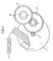
- Fig. 2 is an illustration of a transfer mechanism for transferring a driving force between the conveying roller 6 and the conveying motor 7.
- numeral 12 represents a motor gear fitted over a roller shaft 6a of the conveying roller 6
- numeral 13 signifies an idler gear for transferring the driving force of the conveying motor 7 from the motor gear 12 to a roller gear 14.
- the conveying roller 6 is rotated by a predetermined angle corresponding to the minimum drive unit of the conveying motor 7, so that the recording medium is conveyed by that rotating quantity.
- Fig. 3 is a block diagram showing an arrangement of the control circuit 8 in Fig. 8.
- a CPU 16 which is a microprocessor e.g., is connected through an interface circuit 17 being in connection with a common bus line 26 to a host computer 15.
- the CPU 16 controls the operation of recording apparatus on the basis of a recording control program stored in a program memory 18 serving as a ROM or record data (print data) stored in a buffer memory 19 acting as a RAM and outputted from the host computer 15.
- the CPU 16 controls a carriage driver 24 connected to the common bus line 26, the carriage motor 3 through a conveyance driver 25, and the conveying motor 7, and further controls the ink discharge from the nozzles of the print head 1 through the use of a head driver 23 on the basis of the print data stored in the RAM 19.
- An operating panel 20 is provided for the purpose of the operation of the recording apparatus, where the user can confirm the printing condition of the recording apparatus.
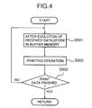
- Figs. 4 and 5 are flow charts showing a basic recording operation of the recording apparatus.
- a step S501 the CPU 16 expands a print signal received from the host computer 15 and sets the expanded print signal in a buffer memory of the RAM 19 for one scan so that it is printable by the print head 1.
- step S502 the CPU 16 carries out the printing operation through the use of the print head 1 on the basis of the print data stored in the buffer memory, and in a step S503, waits for the completion of the printing operation.
- a step S601 the CPU 16 drives the carriage motor 3 to make the carriage 2 scan the recording medium 11, while, in a step S602, shooting ink from the nozzles of the ink jet type print head 1 mounted on the carriage 2 to form ink dots on the recording medium, thus conducting the printing operation.
- step S604 After the completion of the printing of all of the print data in a line buffer in a step S603 (Yes in step S603), in a step S604, the conveying roller 6 is driven by the conveying roller 7 so that the recording medium is forwarded by a predetermined quantity Ln in the paper feed direction (sub-scanning direction).
- a step S605 the carriage 2 is returned to the start position, and the one-line printing operation reaches completion. Thereafter, in the case that the received data for the second line and the lines subsequent thereto are stored in the buffer memory, the operations of the steps S501 to S503 are repeatedly put into practice.
- Fig. 6 is an enlarged and simplified view showing the vicinity of the discharge ports of the ink jet print head 1 and a simplified view showing a configuration of the ink droplets 27.
- discharge ports la are made at an interval corresponding to a pitch Ph, and ink droplets 27 are discharged at the pitch Ph at the scanning of the print head 1 by the carriage 2. That is, recording dots are formed along the feed direction by one scanning of the ink jet print head 1.
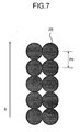
- Fig. 7 is an illustration of recording dots formed on a recording medium. As shown in Fig. 7, recording dots 28 are formed at the pitch Pd along the feed direction S of the recording medium.
- Fig. 8 is an illustration of the variation of the print head 1 relative to a recording medium in the case that the recording medium is forwarded by an arbitrary distance Lx in the feed direction S.
- Fig. 9 is an illustration of the relationship among a feed quantity L of a recording medium corresponding to the minimum drive unit of a conveying motor (for example, one step of a stepping motor), a pitch Ph of nozzles of a print head and a pitch Pd of recording dots to be formed on the recording medium in a first embodiment.
- the first embodiment is realizable with the recording apparatus shown in Fig. 1.
- the print head nozzle pitch Ph is twice the pitch Pd of recording dots to be formed on the recording medium
- the feed quantity L of the recording medium corresponding to the minimum drive unit of the conveying motor is set to three times the pitch Pd of recording dots to be formed on the recording medium.
- a print column C0 indicates the nozzle positions of the print head along the recording medium feed direction S, and each of the nozzle positions is expressed with a number allocated to each of the recording dots.
- the print head is shifted by the feed quantity L with respect to the recording medium, and therefore, recording dots are formed on the recording medium in a state of being shifted by the feed quantity L at the predetermined recording dot pitch Pd.
- the printing is feasible in a state where the print head is shifted relatively with respect to the recording medium, and even in the case of using a print head having nozzles disposed at a nozzle pitch 2Pd being twice the recording dot pitch Pd, the formation of recording dots is realizable at a predetermined recording dot pitch Pd.
- Fig. 10 also shows an example of recording dots formed by scanning the print head plurality of times. Each numerals of the dots corresponds to the nozzles respectively.
- the pitch Ph of nozzles in a print head and the pitch Pd of recording dots to be formed on the recording medium are set on the above-mentioned condition, as compared with the case that the feed quantity L of a recording medium corresponding to the minimum drive unit of a drive motor is set to be equal to the recording dot pitch Pd like the prior art, the recording medium can be forwarded at a several times higher speed.
- the recording medium feed speed is set to be equal to that in the prior art, even a low-priced stepping motor providing a lower number of steps to be taken per a constant time is available, which contributes to the reduction of the cost of the recording apparatus.
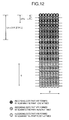
- Fig. 11 is an illustration of the relationship among a feed quantity L of a recording medium corresponding to the minimum drive unit of a conveying motor, a picth Ph of nozzles of a print head and a pitch Pd of recording dots to be formed on the recording medium in a second embodiment.
- the second embodiment is realizable with the recording apparatus shown in Fig. 1.
- the print head nozzle pitch Ph is twice the pitch Pd of recording dots to be formed on the recording medium
- the feed quantity L of the recording medium corresponding to the minimum drive unit of the conveying motor is 1.5 times the pitch Pd of recording dots to be formed on the recording medium.
- a print column C0 indicates nozzle positions of the print head along the feed direction S of the recording medium, and each of the nozzle positions is represented by each of numbers.
- the print head is shifted relatively with the recording medium as indicated by print columns C1 and C2, and hence, dots can be formed on the recording medium at the predetermined recording dot pitch Pd.
- the print head can be shifted relatively with respect to the recording medium, and even in the case of using a print head having nozzles disposed at the nozzle pitch 2Pd being twice the recording dot pitch Pd, the formation of recording dots is realizable at the predetermined recording dot pitch Pd.
- Fig. 12 also shows an example of recording dots formed by scanning the print head plurality of times. Each numerals of the dots corresponds to the nozzles respectively.
- the pitch Ph of nozzles in a print head and the pitch Pd of recording dots to be formed on the recording medium are set on the above-mentioned condition, as compared with the case that the feed quantity L of a recording medium corresponding to the minimum drive unit of a drive motor is set to be equal to the recording dot pitch Pd like the prior art, the recording medium can be forwarded at a several times higher speed.
- the recording medium feed speed is set to be equal to that in the prior art, even a low-priced stepping motor providing a lower number of steps to be taken per a constant time is available, which contributes to the reduction of the cost of the recording apparatus.
- the feed quantity Ln in the feed direction S is always taken to be even-number times the minimum drive unit of the conveying motor (that is, integer times of 2L), and therefore, if the motor to be put to use is a two-phase stepping motor, the factor to the rotational angle errors due to the phase of the motor is reset at 2L, thereby providing higher-accuracy feeding (sub-scanning).
- Fig. 13 is an illustration of the relationship among a feed quantity L of a recording medium corresponding to the minimum drive unit of a conveying motor, a pitch Ph of nozzles in a print head and a pitch Pd of recording dots to be formed on the recording medium in a third embodiment.
- the third embodiment is realizable with the recording apparatus shown in Fig. 1.
- the print head nozzle pitch Ph is three times the pitch Pd of recording dots to be formed on a recording medium
- the feed quantity L of the recording medium corresponding to the minimum drive unit of a conveying motor is twice the pitch Pd of recording dots to be formed on the recording medium.
- a print column C0 denotes nozzle positions of the print head along the feed direction of the recording medium, and each of the nozzle positions is expressed by each of numbers.
- the print head is shifted relatively with the recording medium as indicated by print columns C1 and C2, and hence, recording dots can be formed on the recording medium at the predetermined recording dot pitch Pd.
- the print head can be shifted relatively, and even in the case of using a print head having nozzles disposed at the nozzle pitch 3Pd being three times the recording dot pitch Pd, the formation of recording dots is realizable at the predetermined recording dot pitch Pd.
- Fig. 14 also shows an example of recording dots formed by scanning the print head plurality of times. Each numerals of the dots corresponds to the nozzles respectively.
- the pitch Ph of nozzles in a print head and the pitch Pd of recording dots to be formed on the recording medium are set on the above-mentioned condition, as compared with the case that the feed quantity L of a recording medium corresponding to the minimum drive unit of a drive motor is set to be equal to the recording dot pitch Pd like the prior art, the recording medium can be forwarded at a several times higher speed.
- the recording medium feed speed is set to be equal to that in the prior art, even a low-priced stepping motor providing a lower number of steps to be taken per a constant time is available, which contributes to the reduction of the cost of the recording apparatus.
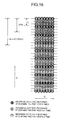
- Fig. 15 is an illustration of the relationship among a feed quantity L of a recording medium corresponding to the minimum drive unit of a conveying motor, a pitch Ph of nozzles of a print head and a pitch Pd of recording dots to be formed on the recording medium in a fourth embodiment.
- the fourth embodiment is also realizable with the recording apparatus shown in Fig. 1.
- the print head nozzle pitch Ph is three times the pitch Pd of recording dots to be formed on the recording medium
- the feed quantity L of the recording medium corresponding to the minimum drive unit of the conveying motor is 2.5 times the pitch Pd of recording dots to be formed on the recording medium.
- a print column C0 indicates nozzle positions of the print head along the feed direction S of the recording medium, and each of the nozzle positions is represented by each of numbers.
- the print head is shifted relatively with the recording medium as indicated by print columns C1 and C2, and hence, recording dots can be formed on the recording medium at the predetermined recording dot pitch Pd.
- the print head can be shifted relatively with respect to the recording medium, and even in the case of using a print head having nozzles disposed at the nozzle pitch 3Pd being three times the recording dot pitch Pd, the formation of recording dots is realizable at the predetermined recording dot pitch Pd.
- Fig. 16 also shows an example of recording dots formed by scanning the print head plurality of times. Each numerals of the dots corresponds to the nozzles respectively.
- the pitch Ph of nozzles in a print head and the pitch Pd of recording dots to be formed on the recording medium are set on the above-mentioned condition, as compared with the case that the feed quantity L of a recording medium corresponding to the minimum drive unit of a drive motor is set to be equal to the recording dot pitch Pd like the prior art, the recording medium can be forwarded at a several times higher speed.
- the recording medium feed speed is set to be equal to that in the prior art, even a low-priced stepping motor providing a lower number of steps to be taken per a constant time is available, which contributes to the reduction of the cost of the recording apparatus.
- the feed quantity Ln in the feed direction S is always taken to be even-number times the minimum drive unit of the conveying motor (that is, integer times of 2L), and therefore, if the motor to be put to use is a two-phase stepping motor, the factor to the rotational angle errors due to the phase of the motor is reset at 2L, thereby providing higher-accuracy feeding (sub-scanning).
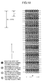
- Fig. 17 is an illustration of the relationship among a feed quantity L of a recording medium corresponding to the minimum drive unit of a conveying motor, a pitch Ph of nozzles of a print head and a pitch Pd of recording dots to be formed on the recording medium in a fifth embodiment.
- the fifth embodiment is also realizable with the recording apparatus shown in Fig. 1.
- the print head nozzle pitch Ph is four times the pitch Pd of recording dots to be formed on the recording medium
- the feed quantity L of the recording medium corresponding to the minimum drive unit of the conveying motor is three times the pitch Pd of recording dots to be formed on the recording medium.
- a print column C0 indicates nozzle positions of the print head along the feed direction S of the recording medium, and each of the nozzle positions is represented by each of numbers.
- the print head is shifted relatively with the recording medium as indicated by print columns C1, C2 and C3, and hence, recording dots can be formed on the recording medium at the predetermined recording dot pitch Pd.
- the print head nozzle pitch Ph is four times the pitch Pd of recording dots to be formed on the recording medium and the feed quantity L of the recording medium corresponding to the minimum drive unit of the conveying motor is twice the recording dot pitch Pd, as shown in Fig. 19, difficulty is encountered in relatively shifting the print head in the feed direction except positions corresponding to even-number times of Pd as integer times the minimum drive unit.
- the print head can be shifted relatively with respect to the recording medium, and even in the case of using a print head having nozzles disposed at the nozzle pitch 4Pd being four times the recording dot pitch Pd, the formation of recording dots is feasible at the predetermined recording dot pitch Pd.
- Fig. 18 also shows an example of recording dots formed by scanning the print head plurality of times. Each numerals of the dots corresponds to the nozzles respectively.
- the pitch Ph of nozzles in a print head and the pitch Pd of recording dots to be formed on the recording medium are set on the above-mentioned condition, as compared with the case that the feed quantity L of a recording medium corresponding to the minimum drive unit of a drive motor is set to be equal to the recording dot pitch Pd like the prior art, the recording medium can be forwarded at a several times higher speed.
- the recording medium feed speed is set to be equal to that in the prior art, even a low-priced stepping motor providing a lower number of steps to be taken per a constant time is available, which contributes to the reduction of the cost of the recording apparatus.
- inventions can accomplish the enhancement of the record density and precision by employing, particularly of ink jet recording types, a type which is equipped with a means (for example, an electro-thermal transducer or laser light) to generate thermal energy as an energy to be used for discharging ink and causes a state variation of the ink by the thermal energy.
- a means for example, an electro-thermal transducer or laser light
- the typical construction and principle are based upon the basic principle disclosed in U.S.P No. 7423129 or U.S.P No. 4740796.
- this type is applicable to both so-called on-demand type and continuous type, particularly, the on-demand type is effective because, in a manner that at least one drive signal corresponding to record information for providing a rapid temperature rise exceeding the film boiling is applied to an electro-thermal transducer located in connection with a sheet retaining a liquid (ink) or a liquid passage, the electro-thermal transducer is made to generate thermal energy to cause the film boiling on a heat working surface of a print head so that the formation of a bubble in the liquid (ink) is possible in one-to-one relation to this drive signal.
- the liquid (ink) is discharged through a discharging opening by the growth and contraction to develop at least one droplet. If this drive signal is made in the form of a pulse, since the growth and contraction of the bubble immediately and appropriately take place, liquid (ink) discharge excellent in response is achievable, and therefore, it is more preferable.
- this invention covers the construction in which a heat working surface exists in a bent area, disclosed in U.S.P. No. 4558333 or U.S.P. No. 4459600. besides, it is also possible to use the construction in which a slot common to a plurality of electro-thermal transducers is used as a discharging section of the electro-thermal transducers as disclosed in Japanese Unexamined Patent Publication No. 59-123670 or employ the construction in which an opening for absorbing pressure waves of thermal energy is made to correspond to a discharging section as disclosed in Japanese Unexamined Patent Publication No. 59-138461.
- a recovery means for the print head, an preliminary means or the like to the above-described constructions of the recording apparatus.
- the means to be added there are a capping means for the print head, a cleaning means, a pressurizing or sucking means, an electro-thermal transducer, a different heating device, a preliminary heating means comprising a combination of heating devices, and others.
- having a preliminary discharging mode for conducting the discharge which is not for the recording is also effective with a view to effecting stable recording.
- the recording mode of the recording apparatus in addition to a recording mode using only a main color such as black, it is possible to take a means for providing a plurality of different colors or at least one of full color based on color mixture by using an integrally constructed print head or a combination of a plurality of print heads.
- ink solidified at the room temperature or below or to use ink softened or liquefied at the room temperature.
- ink taking a liquid condition at the supply of a record signal to be used, for that, in general, in the ink jet type, the temperature control is done such that the ink itself is temperature-adjusted within a range between 30°C and 70°C to put the viscosity of the ink within a stable discharge range.
- this invention is also applicable to the case of using ink liquefied by giving thermal energy corresponding to a record signal so that the liquefied ink is discharged and the case of using ink having a property whereby solidification starts at the arrival of the recording medium and liquefaction occurs for the first time due to the supply of thermal energy.
- the ink faces the electro-thermal transducer in a state of being held in recess portions of a porous sheet or through holes thereof as a liquid material or a solid material as disclosed in Japanese Unexamined Patent Publication No. 54-56847 or No. 60-71260.
- the aforesaid film boiling type is most effective to the above-mentioned ink.
- the recording apparatus can be a recording apparatus serving as an image outputting terminal of information processing equipment such as a computer integrally or separately installed, a copying machine including a reader, or a facsimile having a signal transmission and reception function.
- This invention is applicable to a system comprising a plurality of equipment (for example, a host computer, an interface device, a reader, a printer, and others) or to an apparatus comprising one equipment (for example, a copying machine, a facsimile, and others).
- equipment for example, a host computer, an interface device, a reader, a printer, and others
- apparatus comprising one equipment (for example, a copying machine, a facsimile, and others).
- the object of this invention is achievable even in a manner that a storage medium storing a program code of a software for realizing the functions of the above-described embodiments is supplied to a system or an apparatus and a computer (CPU or MPU) of the system or the apparatus reads out and implements the program code from the storage medium.
- a storage medium storing a program code of a software for realizing the functions of the above-described embodiments is supplied to a system or an apparatus and a computer (CPU or MPU) of the system or the apparatus reads out and implements the program code from the storage medium.
- the program code itself read out from the recording medium realizes the function of each of the above-described embodiments, and the storage medium storing the program code constitutes this invention.
- the storage medium to be used for the supply of the program code for example, there are a floppy disk, a hard disk, an optical disk, a magneto optical disk, a CD-ROM, a CD-R, a magnetic tape, a non-volatile memory card, a ROM, and others.
- this invention covers the case that the functions of the above-described embodiments can be fulfilled in a manner that the computer executes the program code read out, and the case that an OS (Operating System) or the like operating on the computer conducts a portion of or all the actual processing in accordance with an instruction indicated by the program code to realize the functions of the above-described embodiments.
- OS Operating System
- this invention covers the case that, after the program code read out from the storage medium is written in a memory associated with an extended board inserted into the computer or an extended unit connected to the computer, the CPU concerned with the extended board or the extended unit executes a portion of or all the actual processing on the basis of an instruction indicated by the program code to fulfill the functions of the above-described embodiments.
- ink is discharged from the print head onto a recording medium at a recording dot pitch obtained by dividing a predetermined pitch of discharge ports by an integer above 2, and the medium drive means is controlled so that the feed quantity of the recording medium corresponding to the minimum drive unit of the medium drive means becomes larger than a pitch of recording dots to be formed on the recording medium, whereupon it is possible to increase the recording medium feed speed, to reduce the cost, and further, to accomplish high-quality recording at a small recording dot pitch.
- the medium drive means is controlled to satisfy the condition that, when the pitch of discharge ports is taken to be Ph and the recording dot pitch is taken as Pd, Ph/Pd ⁇ 2 and L > Pd, whereupon it is possible to increase the recording medium feed speed, to reduce the cost, and further, to accomplish high-quality recording at a small recording dot pitch.
Landscapes
- Ink Jet (AREA)
- Particle Formation And Scattering Control In Inkjet Printers (AREA)
- Character Spaces And Line Spaces In Printers (AREA)
- Dot-Matrix Printers And Others (AREA)
Applications Claiming Priority (2)
| Application Number | Priority Date | Filing Date | Title |
|---|---|---|---|
| JP35500197 | 1997-12-24 | ||
| JP9355001A JPH11179890A (ja) | 1997-12-24 | 1997-12-24 | 記録装置及びその制御方法 |
Publications (3)
| Publication Number | Publication Date |
|---|---|
| EP0925950A2 true EP0925950A2 (fr) | 1999-06-30 |
| EP0925950A3 EP0925950A3 (fr) | 1999-10-27 |
| EP0925950B1 EP0925950B1 (fr) | 2006-02-22 |
Family
ID=18441310
Family Applications (1)
| Application Number | Title | Priority Date | Filing Date |
|---|---|---|---|
| EP98310668A Expired - Lifetime EP0925950B1 (fr) | 1997-12-24 | 1998-12-23 | Appareil d'enregistrement et sa méthode de commande |
Country Status (4)
| Country | Link |
|---|---|
| US (1) | US6341834B1 (fr) |
| EP (1) | EP0925950B1 (fr) |
| JP (1) | JPH11179890A (fr) |
| DE (1) | DE69833540T2 (fr) |
Cited By (4)
| Publication number | Priority date | Publication date | Assignee | Title |
|---|---|---|---|---|
| NL1012813C2 (nl) * | 1999-08-12 | 2001-02-13 | Ocu Technologies B V | Werkwijze voor het bedrukken van een substraat en een drukinrichting geschikt om deze werkwijze toe te passen. |
| NL1012816C2 (nl) * | 1999-08-12 | 2001-02-13 | Ocu Technologies B V | Werkwijze voor het bedrukken van een substraat en een drukinrichting geschikt om deze werkwijze toe te passen. |
| EP1623838A1 (fr) * | 2004-07-28 | 2006-02-08 | Brother Kogyo Kabushiki Kaisha | Appareil et méthode d'impression d'images |
| EP1375147A4 (fr) * | 2001-03-28 | 2006-03-22 | Seiko Epson Corp | Enregistreur a jet d'encre et tete d'enregistreur |
Families Citing this family (3)
| Publication number | Priority date | Publication date | Assignee | Title |
|---|---|---|---|---|
| US7393075B2 (en) * | 2003-09-05 | 2008-07-01 | Canon Kabushiki Kaisha | Recording apparatus, and feed control method of recording medium in the apparatus |
| KR100788664B1 (ko) * | 2005-05-26 | 2007-12-26 | 삼성전자주식회사 | 프린트 헤드와 이를 구비하는 스캐닝 방식 잉크젯화상형성장치, 및 고해상도 구현 방법 |
| JP6123997B2 (ja) * | 2013-03-27 | 2017-05-10 | セイコーエプソン株式会社 | 記録装置 |
Citations (8)
| Publication number | Priority date | Publication date | Assignee | Title |
|---|---|---|---|---|
| US4313124A (en) | 1979-05-18 | 1982-01-26 | Canon Kabushiki Kaisha | Liquid jet recording process and liquid jet recording head |
| US4345262A (en) | 1979-02-19 | 1982-08-17 | Canon Kabushiki Kaisha | Ink jet recording method |
| US4423129A (en) | 1980-12-17 | 1983-12-27 | Canon Kabushiki Kaisha | Electrophotographic member having layer containing methylidenyl hydrazone compound |
| US4459600A (en) | 1978-10-31 | 1984-07-10 | Canon Kabushiki Kaisha | Liquid jet recording device |
| JPS59123670A (ja) | 1982-12-28 | 1984-07-17 | Canon Inc | インクジエツトヘツド |
| US4463359A (en) | 1979-04-02 | 1984-07-31 | Canon Kabushiki Kaisha | Droplet generating method and apparatus thereof |
| US4558333A (en) | 1981-07-09 | 1985-12-10 | Canon Kabushiki Kaisha | Liquid jet recording head |
| US4740796A (en) | 1977-10-03 | 1988-04-26 | Canon Kabushiki Kaisha | Bubble jet recording method and apparatus in which a heating element generates bubbles in multiple liquid flow paths to project droplets |
Family Cites Families (9)
| Publication number | Priority date | Publication date | Assignee | Title |
|---|---|---|---|---|
| JPS5936879B2 (ja) | 1977-10-14 | 1984-09-06 | キヤノン株式会社 | 熱転写記録用媒体 |
| US4540996A (en) * | 1982-05-11 | 1985-09-10 | Canon Kabushiki Kaisha | Recording apparatus |
| JPS59138461A (ja) | 1983-01-28 | 1984-08-08 | Canon Inc | 液体噴射記録装置 |
| JPS6071260A (ja) | 1983-09-28 | 1985-04-23 | Erumu:Kk | 記録装置 |
| JP2817224B2 (ja) | 1989-07-13 | 1998-10-30 | 松下電器産業株式会社 | カラープリンタ |
| JPH06171084A (ja) | 1992-02-07 | 1994-06-21 | Seiko Epson Corp | インクジェット記録ヘッド |
| US5349375A (en) | 1992-04-16 | 1994-09-20 | Lexmark International, Inc. | Ink jet printer dot placement compensation method |
| US5686944A (en) | 1994-03-02 | 1997-11-11 | Seiko Epson Corporation | Serial printer with hybrid print control of interlaced and minute feed printing |
| US5625390A (en) * | 1995-01-30 | 1997-04-29 | Tektronix, Inc. | Pairing of ink drops on a print medium |
-
1997
- 1997-12-24 JP JP9355001A patent/JPH11179890A/ja active Pending
-
1998
- 1998-12-22 US US09/218,094 patent/US6341834B1/en not_active Expired - Lifetime
- 1998-12-23 DE DE69833540T patent/DE69833540T2/de not_active Expired - Lifetime
- 1998-12-23 EP EP98310668A patent/EP0925950B1/fr not_active Expired - Lifetime
Patent Citations (8)
| Publication number | Priority date | Publication date | Assignee | Title |
|---|---|---|---|---|
| US4740796A (en) | 1977-10-03 | 1988-04-26 | Canon Kabushiki Kaisha | Bubble jet recording method and apparatus in which a heating element generates bubbles in multiple liquid flow paths to project droplets |
| US4459600A (en) | 1978-10-31 | 1984-07-10 | Canon Kabushiki Kaisha | Liquid jet recording device |
| US4345262A (en) | 1979-02-19 | 1982-08-17 | Canon Kabushiki Kaisha | Ink jet recording method |
| US4463359A (en) | 1979-04-02 | 1984-07-31 | Canon Kabushiki Kaisha | Droplet generating method and apparatus thereof |
| US4313124A (en) | 1979-05-18 | 1982-01-26 | Canon Kabushiki Kaisha | Liquid jet recording process and liquid jet recording head |
| US4423129A (en) | 1980-12-17 | 1983-12-27 | Canon Kabushiki Kaisha | Electrophotographic member having layer containing methylidenyl hydrazone compound |
| US4558333A (en) | 1981-07-09 | 1985-12-10 | Canon Kabushiki Kaisha | Liquid jet recording head |
| JPS59123670A (ja) | 1982-12-28 | 1984-07-17 | Canon Inc | インクジエツトヘツド |
Cited By (10)
| Publication number | Priority date | Publication date | Assignee | Title |
|---|---|---|---|---|
| NL1012813C2 (nl) * | 1999-08-12 | 2001-02-13 | Ocu Technologies B V | Werkwijze voor het bedrukken van een substraat en een drukinrichting geschikt om deze werkwijze toe te passen. |
| NL1012816C2 (nl) * | 1999-08-12 | 2001-02-13 | Ocu Technologies B V | Werkwijze voor het bedrukken van een substraat en een drukinrichting geschikt om deze werkwijze toe te passen. |
| EP1075953A1 (fr) * | 1999-08-12 | 2001-02-14 | Océ-Technologies B.V. | Méthode d'impression d'un substrat et un dispositif d'impression adapté à cette méthode |
| EP1075954A1 (fr) * | 1999-08-12 | 2001-02-14 | Océ-Technologies B.V. | Méthode d'impression sur un substrat et un dispositif d'impression adapté pour utiliser cette méthode |
| US6464331B1 (en) | 1999-08-12 | 2002-10-15 | Oce-Technologies B.V. | Method of printing a substrate and a printing device suitable for the use of the method |
| US7066570B1 (en) | 1999-08-12 | 2006-06-27 | Oce-Technologies B.V. | Method of printing a substrate and a printing device suitable for use of the method |
| EP1375147A4 (fr) * | 2001-03-28 | 2006-03-22 | Seiko Epson Corp | Enregistreur a jet d'encre et tete d'enregistreur |
| US7073888B2 (en) | 2001-03-28 | 2006-07-11 | Seiko Epson Corporation | Ink jet recording device, and recording head |
| EP1623838A1 (fr) * | 2004-07-28 | 2006-02-08 | Brother Kogyo Kabushiki Kaisha | Appareil et méthode d'impression d'images |
| US7422298B2 (en) | 2004-07-28 | 2008-09-09 | Brother Kogyo Kabushiki Kaisha | Inkjet recording apparatus and recording method |
Also Published As
| Publication number | Publication date |
|---|---|
| JPH11179890A (ja) | 1999-07-06 |
| US6341834B1 (en) | 2002-01-29 |
| DE69833540D1 (de) | 2006-04-27 |
| DE69833540T2 (de) | 2006-09-07 |
| EP0925950B1 (fr) | 2006-02-22 |
| EP0925950A3 (fr) | 1999-10-27 |
Similar Documents
| Publication | Publication Date | Title |
|---|---|---|
| EP1013423B1 (fr) | Tête d'impression à jet d'encre et appareil l'utilisant | |
| EP0595658A2 (fr) | Appareil d'enregistrement par jet d'encre | |
| EP1264697B1 (fr) | Appareil à imprimer des images et procédé de commande associé, support de stockage et programme | |
| EP0533486B1 (fr) | Méthode pour l'enregistrement en série capable de varier la résolution | |
| JP2008279616A (ja) | 記録装置、及びクロック生成方法 | |
| US5485178A (en) | Printer control apparatus for synchronously controlling driving of recording head and transfer of data | |
| US6655772B2 (en) | Printing apparatus and printhead temperature management method | |
| US6341834B1 (en) | Recording apparatus and control method thereof | |
| EP1355262A2 (fr) | Impression en série bi-directionelle | |
| JP3576782B2 (ja) | 記録装置及び記録制御方法 | |
| US7315393B2 (en) | Printing system, printer driver, and printing method | |
| EP0608880B1 (fr) | Appareil pour la formation d'images | |
| EP1355264B1 (fr) | Appareil et procédé d'impression | |
| US7126715B2 (en) | Ink jet recording apparatus and control method therefor | |
| JPH11179915A (ja) | プリントヘッド、プリント装置およびプリント方法 | |
| US6652065B2 (en) | Printing apparatus and control method therefor | |
| US6086184A (en) | Recording control method and recording control apparatus, and recording apparatus and recording system using the recording control apparatus | |
| EP1116587B1 (fr) | Imprimante et procédé d'imprimer | |
| US7206095B2 (en) | Printing apparatus and method | |
| US6559960B2 (en) | Image processing apparatus and method that sets a printing mode based on image data to be printed | |
| US5984453A (en) | Recording apparatus and method by time-division drive | |
| JPH07246718A (ja) | プリント装置およびプリント方法 | |
| US6478409B1 (en) | Printing apparatus and printing control method | |
| JP2002254612A (ja) | 画像記録装置および画像記録方法 | |
| JP2000015867A (ja) | プリント装置およびプリント方法 |
Legal Events
| Date | Code | Title | Description |
|---|---|---|---|
| PUAI | Public reference made under article 153(3) epc to a published international application that has entered the european phase |
Free format text: ORIGINAL CODE: 0009012 |
|
| AK | Designated contracting states |
Kind code of ref document: A2 Designated state(s): DE FR GB IT |
|
| AX | Request for extension of the european patent |
Free format text: AL;LT;LV;MK;RO;SI |
|
| PUAL | Search report despatched |
Free format text: ORIGINAL CODE: 0009013 |
|
| AK | Designated contracting states |
Kind code of ref document: A3 Designated state(s): AT BE CH CY DE DK ES FI FR GB GR IE IT LI LU MC NL PT SE |
|
| AX | Request for extension of the european patent |
Free format text: AL;LT;LV;MK;RO;SI |
|
| 17P | Request for examination filed |
Effective date: 20000310 |
|
| AKX | Designation fees paid |
Free format text: DE FR GB IT |
|
| 17Q | First examination report despatched |
Effective date: 20030602 |
|
| GRAP | Despatch of communication of intention to grant a patent |
Free format text: ORIGINAL CODE: EPIDOSNIGR1 |
|
| GRAS | Grant fee paid |
Free format text: ORIGINAL CODE: EPIDOSNIGR3 |
|
| GRAA | (expected) grant |
Free format text: ORIGINAL CODE: 0009210 |
|
| AK | Designated contracting states |
Kind code of ref document: B1 Designated state(s): DE FR GB IT |
|
| PG25 | Lapsed in a contracting state [announced via postgrant information from national office to epo] |
Ref country code: IT Free format text: LAPSE BECAUSE OF FAILURE TO SUBMIT A TRANSLATION OF THE DESCRIPTION OR TO PAY THE FEE WITHIN THE PRE;WARNING: LAPSES OF ITALIAN PATENTS WITH EFFECTIVE DATE BEFORE 2007 MAY HAVE OCCURRED AT ANY TIME BEFORE 2007. THE CORRECT EFFECTIVE DATE MAY BE DIFFERENT FROM THE ONE RECORDED.SCRIBED TIME-LIMIT Effective date: 20060222 |
|
| REG | Reference to a national code |
Ref country code: GB Ref legal event code: FG4D |
|
| REF | Corresponds to: |
Ref document number: 69833540 Country of ref document: DE Date of ref document: 20060427 Kind code of ref document: P |
|
| PLBE | No opposition filed within time limit |
Free format text: ORIGINAL CODE: 0009261 |
|
| STAA | Information on the status of an ep patent application or granted ep patent |
Free format text: STATUS: NO OPPOSITION FILED WITHIN TIME LIMIT |
|
| 26N | No opposition filed |
Effective date: 20061123 |
|
| EN | Fr: translation not filed | ||
| PG25 | Lapsed in a contracting state [announced via postgrant information from national office to epo] |
Ref country code: FR Free format text: LAPSE BECAUSE OF FAILURE TO SUBMIT A TRANSLATION OF THE DESCRIPTION OR TO PAY THE FEE WITHIN THE PRESCRIBED TIME-LIMIT Effective date: 20070309 |
|
| PG25 | Lapsed in a contracting state [announced via postgrant information from national office to epo] |
Ref country code: FR Free format text: LAPSE BECAUSE OF FAILURE TO SUBMIT A TRANSLATION OF THE DESCRIPTION OR TO PAY THE FEE WITHIN THE PRESCRIBED TIME-LIMIT Effective date: 20060222 |
|
| PGFP | Annual fee paid to national office [announced via postgrant information from national office to epo] |
Ref country code: GB Payment date: 20151218 Year of fee payment: 18 |
|
| PGFP | Annual fee paid to national office [announced via postgrant information from national office to epo] |
Ref country code: DE Payment date: 20151231 Year of fee payment: 18 |
|
| REG | Reference to a national code |
Ref country code: DE Ref legal event code: R119 Ref document number: 69833540 Country of ref document: DE |
|
| GBPC | Gb: european patent ceased through non-payment of renewal fee |
Effective date: 20161223 |
|
| PG25 | Lapsed in a contracting state [announced via postgrant information from national office to epo] |
Ref country code: GB Free format text: LAPSE BECAUSE OF NON-PAYMENT OF DUE FEES Effective date: 20161223 Ref country code: DE Free format text: LAPSE BECAUSE OF NON-PAYMENT OF DUE FEES Effective date: 20170701 |