EP0926060A2 - Bâteau réducteur de friction et méthode pour la réduction de la friction superficielle - Google Patents
Bâteau réducteur de friction et méthode pour la réduction de la friction superficielle Download PDFInfo
- Publication number
- EP0926060A2 EP0926060A2 EP98402042A EP98402042A EP0926060A2 EP 0926060 A2 EP0926060 A2 EP 0926060A2 EP 98402042 A EP98402042 A EP 98402042A EP 98402042 A EP98402042 A EP 98402042A EP 0926060 A2 EP0926060 A2 EP 0926060A2
- Authority
- EP
- European Patent Office
- Prior art keywords
- ship
- bubbles
- friction
- gas
- lateral
- Prior art date
- Legal status (The legal status is an assumption and is not a legal conclusion. Google has not performed a legal analysis and makes no representation as to the accuracy of the status listed.)
- Withdrawn
Links
Images

Classifications
-
- B—PERFORMING OPERATIONS; TRANSPORTING
- B63—SHIPS OR OTHER WATERBORNE VESSELS; RELATED EQUIPMENT
- B63B—SHIPS OR OTHER WATERBORNE VESSELS; EQUIPMENT FOR SHIPPING
- B63B1/00—Hydrodynamic or hydrostatic features of hulls or of hydrofoils
- B63B1/32—Other means for varying the inherent hydrodynamic characteristics of hulls
- B63B1/34—Other means for varying the inherent hydrodynamic characteristics of hulls by reducing surface friction
- B63B1/38—Other means for varying the inherent hydrodynamic characteristics of hulls by reducing surface friction using air bubbles or air layers gas filled volumes
-
- Y—GENERAL TAGGING OF NEW TECHNOLOGICAL DEVELOPMENTS; GENERAL TAGGING OF CROSS-SECTIONAL TECHNOLOGIES SPANNING OVER SEVERAL SECTIONS OF THE IPC; TECHNICAL SUBJECTS COVERED BY FORMER USPC CROSS-REFERENCE ART COLLECTIONS [XRACs] AND DIGESTS
- Y02—TECHNOLOGIES OR APPLICATIONS FOR MITIGATION OR ADAPTATION AGAINST CLIMATE CHANGE
- Y02T—CLIMATE CHANGE MITIGATION TECHNOLOGIES RELATED TO TRANSPORTATION
- Y02T70/00—Maritime or waterways transport
- Y02T70/10—Measures concerning design or construction of watercraft hulls
Definitions
- the present invention relates in general to friction-reducing ships and methods for reducing skin-friction, and relates in particular to a technology for reducing skin-friction by blowing micro-bubbles from the hull into water.
- a practical method that can be applied to a friction-reducing ship is to produce bubbles by blowing compressed air generated by on-board compressors to produce a desired void fraction in a boundary layer at the bottom section of a ship.
- the present inventors have discovered that friction-reducing ships can be made practical, if jetting nozzles are located in low static pressure regions and the bubbly flow fields created at the bottom and hull surfaces of the ship can be made to flow along the hull surfaces. Based on such a premise, the present inventors developed a computational model in which the bubbles are generated in low static pressure regions, and given the shape of a hull structure, the model is able to compute void fractions in any locations about the hull structure by considering the turbulent diffusion of micro-bubbles along the flow lines near the hull surfaces.
- the effects of turbulent diffusion are considered by varying the flow speeds in X-, Y- and Z-directions (levitation direction) so as to create turbulence in the traces of micro-bubbles flowing about the hull surfaces.
- random activities of the bubbles are simulated directly by using Monte Carlo methods.
- a void fraction at a given point in time can be obtained by dividing the volume of the micro-bubbles existing in a given volume of an inspection volume (cell volume) by the volume of the cell.
- optimum configuration of the gas jetting devices located at the bow of a ship where maximum friction reduction effects are expected, can be determined in relation to the flow lines originating in those locations and spreading along the hull surfaces towards the stern of the ship.
- the bubbles ejected from the bow of the ship into the boundary layer are carried along with the flow lines in such a way that those bubbles in the leading regions of the bottom section will flow along the bottom surface, but those bubbles in the latter regions of the ship will tend to flow along the lateral surfaces of the ship.
- the ultimate result is that the bubbles are able to blanket the entire submerged surfaces of the moving ship to provide effective friction reduction.
- the micro-bubbles blanketing the hull surfaces can contribute more effectively to friction reduction if they can cling to the hull surfaces.
- the force to keep the bubbles close to the hull surface is only the lift force (Saffman's lift) derived from a difference between the shear flow speed and the bubble flow speed. The magnitude of this lift force is relatively small and the bubbles are quickly carried away from the hull surface.
- This behavior of the lateral bubbles means that they cannot contribute effectively to reducing the skin-friction, because, a boundary layer is generally formed thin near the bow and becomes thicken towards the stern of a ship, therefore, if the gas flow rate through the gas jetting device is adjusted to maximize bubble retention in a thick boundary layer, the bubbles are blown out of the boundary layer from a thinner boundary layer. Therefore, it is critical to control bubble generation conditions so as to retain the bubbles within the boundary layer under all operating conditions of the ship to maximize the friction reduction effects of the micro-bubbles.
- the present invention aims to provide a technology to enable the following broad technical objectives:
- the objectives have been achieved in a method for reducing skin-friction in a ship by blowing gas from a moving ship into water to generate bubbles on submerged surfaces in such a way that bubbles are generated at locations separated at specific distances along a longitudinal direction.
- a friction-reducing ship based on the method which reduces skin-friction by jetting air from a moving ship into water to form bubbles on submerged hull surfaces, is comprised by: a plurality of gas jetting devices for jetting gas into water disposed at specific distances along a longitudinal direction; and a gas supply facility for supplying gas to the gas jetting devices.
- the method is applied effectively to a friction-reducing ship so that the bubbles produced by succeeding jetting devices become enclosed by the bubbles produced by preceding jetting devices in the longitudinal direction or moving direction of the ship.
- the bubbles are thus prevented from flowing away from the turbulent boundary layer, enabling more of the bubbles to be trapped and distributed within the turbulent boundary layer, thereby raising the void fraction and reducing skin-friction using a relatively small amount of the jetting gas.
- the objectives are achieved through a technique developed in the present invention to force the lateral bubbles towards the side hull plates of the ship to further enhance the skin-friction reduction effects in a ship.
- the technique is applied to a friction-reducing ship for reducing skin-friction by generating bubbles by blowing compressed air into water, at submerged lateral locations where flow lines lead to a bottom section or lateral hull sections, in a bow section of a moving ship, wherein those side hull plates disposed in a longitudinal mid-section of the ship are slanted outwards at an angle to a plane vertical to the bottom section. Because the side hull plates are angled outward, the lift force for the lateral bubbles is subjected to a lateral force to push the bubbles towards the hull surface, and the blanketing action of the lateral bubbles is further enhanced to lead to effective friction reduction.
- the objectives are achieved through another technique developed in the present invention to increase the dwell time of the bubbles directed into the boundary layer.
- This is a method for reducing skin-friction of a moving ship by blowing compressed air from a ship into water to generate bubbles to be injected into a boundary layer to produce a blanket of bubbles to cover submerged surfaces of the ship, wherein the compressed air is ejected at a jetting speed higher than a ship speed at an angle to the submerged lateral surfaces towards a stern section, in such a way that diameters of lateral bubbles are smaller than those of bottom bubbles.
- Figure 1 is an external side view of a friction-reducing ship of a first embodiment.
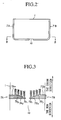
- Figure 2 is a cross sectional front view through a plane A-A in Figure 1.
- Figure 3 is a cross sectional plan view through a plane B-B in Figure 2.
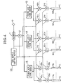
- Figure 4 is a schematic diagram of the gas flow control configuration in the first embodiment.
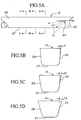
- Figure 5A is a side view of a friction-reducing ship of a second embodiment.
- Figure 5B is a cross sectional view through a plane A-A in Figure 5A.
- Figure 5C is a cross sectional view through a plane B-B in Figure 5A.
- Figure 5D is a cross sectional view through a plane C-C in Figure 5A.
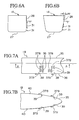
- Figure 6A is a first schematic illustration of the movement of the micro-bubbles in the second embodiment.
- Figure 6B is a second schematic illustration of the movement of the micro-bubbles in the second embodiment.
- Figure 7A is a schematic side view of the bow section of a ship in a third embodiment.
- Figure 7B is a cross sectional view through a plane A-A in Figure 7A.
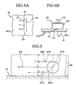
- Figure 8A is a side view of the air jetting devices provided on the lateral hull surfaces of a ship in a third embodiment.
- Figure 8B is a cross sectional top view of the air jetting device shown in Figure 8A.
- Figure 9 is a schematic illustration of the principle of generation of lift forces acting on the micro-bubbles within the boundary layer.
- This embodiment relates to an application of the present invention to a tanker vessel which is characterized by a relatively flat bottom section.
- Figure 1 shows a ship 1, the bow 2, the stern 3, submerged surfaces 4, a screw 5, a rudder 6, gas jetting devices 7 ⁇ 9, the ship movement direction F, and the waterline W.
- the ship 1 is provided with a plurality of bubble generation sections (three sections in this case) which are separated at certain distances in the longitudinal direction (from the bow 2 to the stem 3) and provided with the gas jetting device 7 ⁇ 9.
- the gas jetting device 7 is comprised by a piping path 7A extending from the starboard side to the flat plate bottom section 1a on the hull surfaces of the ship 1, and a piping path 7B extending from the port side to the flat plate bottom section 1a on the hull surfaces of the ship 1.
- These piping paths 7A, 7B are attached in a wrap around manner to the exterior plate of the ship 1, in this case, and are made as flat as possible so as not to protrude out of the ship I to increase the skin-friction.
- the piping path 7A is comprised by a plurality of pipes 7A1 ⁇ 7A4 (four lines), arranged in such a way that, for those pipes which are closer to the stern end of the ship 1, the terminal ends are displaced closer to the lateral hull surfaces.
- the piping path 7B is constructed in a similar way so that a plurality of pipes 7B1 ⁇ 7B4 (four lines), are arranged in such a way that, for those pipes which are closer to the stern end of the ship 1, the terminal ends are displaced closer to the lateral hull surfaces.
- the terminal ends of the pipes 7A1 ⁇ 7A4 and 7B1 ⁇ 7B4 are provided with numerous holes for jetting out air (gas) into water (towards the stern direction) on the stern-side of the terminal ends.
- the gas jetting devices 8, 9 are constructed in exactly the same manner.
- Figure 4 shows a gas supply facility comprised by: an air intake opening 10; a blower 11; a master flowmeter 12; a first air tank group 13; a second air tank group 14; a third air tanks group 15; control valves 16a, 16b, 17a, 17b, 18a and 18b; dedicated flowmeters 19a, 19b, 20a, 20b, 21a, and 21b; a gas supply control device 22.
- pipes 7A1 ⁇ 7A4 and 7B1 ⁇ 7B4 have already been explained above, but pipes 8A1 ⁇ , 8B1 ⁇ are for use in the gas jetting device 8, and pipes 9A1 ⁇ , 9B1 ⁇ are for use in the gas jetting device 9.
- the gas control system operates as follows.
- the blower 11 delivers outdoor air received from the air intake opening 10 to the first, second and third air tank groups 13, 14 and 15 through the master flowmeter 12.
- the master flowmeter 12 measures flow rate of air delivered from the blower 11 and outputs it to the gas supply control device 22.
- the first air tank group 13 is for use with the gas jetting device 7, and stores the air sent from the blower 11 under compression.
- the second air tank group 14 is for use with the gas jetting device 8, and stores the air sent from the blower 11 under compression.
- the third air tank group 15 is for use with the gas jetting device 9, and stores the air sent from the blower 11 under compression.
- the control valve 16a operates under the control of the gas supply control device 22, and is used to adjust flow rates of air sent from the first air tank group 13 to be supplied through the dedicated flowmeter 19a to the pipe 7A1 of the gas jetting device 7.
- the control valve 16b operates also under the control of gas supply control device 22, and is used to adjust flow rates of air sent from the first air tank group 13 to be supplied through a dedicated flowmeter 19b to the pipe 7B1 of the gas jetting device 7.
- the control valve 17a operates under the control of the gas supply control device 22, and is used to adjust flow rates of air sent from the second air tank group 14 to be supplied through the dedicated flowmeter 20a to the pipe 8A1 of the gas jetting device 8.
- the control valve 17b operates also under the control of the gas supply control device 22, and is used to adjust flow rates of air sent from the second air tank group 14 to be supplied through the dedicated flowmeter 20b to the pipe 8B1 of the gas jetting device 8.
- the control valve 18a operates under the control of the gas supply control device 22, and is used to adjust flow rates of air sent from the third air tank group 15 to be supplied through the dedicated flowmeter 21a to the pipe 9A1 of the gas jetting device 9.
- the control valve 18b operates also under the control of the gas supply control device 22, and is used to adjust flow rates of air sent from the third air tank group 15 to be supplied through the dedicated flowmeter 21b to the pipe 9B1 of the gas jetting device 9.
- the dedicated flowmeter 19a measures flow rates of air to be supplied to the pipe 7A1, and outputs the air to the gas supply control device 22.
- the dedicated flowmeter 19b measures flow rates of air to be supplied to the pipe 7B1, and outputs the air to the gas supply control device 22.
- the dedicated flowmeter 20a measures flow rates of air to be supplied to the pipe 8A1, and outputs the air to the gas supply control device 22.
- the dedicated flowmeter 20b measures flow rates of air to be supplied to the pipe 8B1, and outputs the air to the gas supply control device 22.
- the dedicated flowmeter 21a measures flow rates of air to be supplied to the pipe 9A1, and outputs the air to the gas supply control device 22.
- the dedicated flowmeter 21b measures flow rates of air to be supplied to the pipe 9B1, and outputs the air to the gas supply control device 22.
- the other set of pipes 7A2 ⁇ 7A4, 7B2 ⁇ 7B4 comprising the gas jetting device 7 are provided similarly with dedicated control valves and flowmeters.
- the pipes 8A2 ⁇ 8A4, 8B2 ⁇ 8B4 comprising the gas jetting device 8 and the pipes 9A2 ⁇ 9A4, 9B2 ⁇ 9B4 comprising the gas jetting device 9 are provided with dedicated control valves and flowmeters.
- the gas supply control device 22 operates under the guidance of the command device (not shown) located in the steering room, and adjusts the flow rates of air to be supplied to the pipes 7A1 ⁇ 7A4, 7B1 ⁇ 7B4, 8A1 ⁇ 8A4, 8B1 ⁇ 8B4, 9A1 ⁇ 9A4 and 9B1 ⁇ 9B4 by controlling the individual control valves 19a ⁇ , 19b ⁇ , 20a ⁇ , 20b ⁇ , 21a ⁇ , and 21b ⁇ so as to satisfy the target flow rates specified by the command device and the gas flow rates being measured through the master flowmeters 12 and the dedicated flowmeters 16a ⁇ , 16b ⁇ , 17a ⁇ , 17b ⁇ , 18a ⁇ and 18b ⁇ .
- the friction-reducing ship is operated as follows.
- a command is issued to begin operation of the gas supply control device 22, which turns on the blower 11 and begins sending air to the first, second and third air tank groups 13, 14 and 15.
- the control valves 19a ⁇ , 19b ⁇ , 20a ⁇ , 20b ⁇ , 21a ⁇ and 21b ⁇ are opened to supply air to the pipes 7A1 ⁇ 7A4, 7B1 ⁇ 7B4, 8A1 ⁇ 8A4, 8B1 ⁇ 8B4, 9A1 ⁇ 9A4 and 9B1 ⁇ 9B4.
- those micro-bubbles generated in the succeeding gas jetting device 8 (with respect to the preceding gas jetting device 7) are enclosed by the micro-bubbles generated by the gas jetting device 7 and diffusing towards the stern of the ship. Therefore, those micro-bubbles generated by the gas jetting device 8 are also prevented from drifting away from the turbulent boundary layer formed on the surface of the bottom section la, and become contained within the turbulent boundary layer.
- the micro-bubbles generated in the successive gas jetting devices 7 ⁇ 9 are contained within the entire turbulent boundary layer formed over the surface of the bottom section 1a, thereby providing an effective means for reducing skin-friction for a ship 1 having a bottom section 1a which is flat over an extended area, while conserving the volume of gas supplied to the gas jetting devices 7 ⁇ 9.
- the first embodiment utilizes a characteristic that, in a flat-bottomed ship, micro-bubbles are less likely to escape from the hull surface, and micro-bubbles are provided only in the turbulent boundary layer associated with the bottom section 1a of the ship 1. Considering a balance between an energy saved due to friction reduction and an energy consumed by operating the gas supply facility, if a ship 1 has a relatively wide area of flat bottom section 1a, an approach of jetting air only on the bottom section 1a is considered to be more economical.
- the gas jetting devices 7 ⁇ 9 comprised by pipes are wrapped around the outer plate of the ship 1, the embodied technique can be easily applied to ships that do not currently have gas jetting devices. Also, the gas jetting devices 7 ⁇ 9 are attached in such a way that one set of pipes are installed from the starboard side towards the flat plate of the bottom section 1a while the other set of pipes are installed from the port side towards the bottom section 1a. Therefore, compared to a case of continuous pipes wrapped around the hull from the starboard to the port side, the length of the piping path can be made shorter, and enables to lower the energy consumption for driving the gas supply facility.
- Ship 1A includes: the bow section 25; the stern section 26; the bottom section 27; side hull plates 28; and a plurality of gas jetting devices 30 for jetting compressed air. Micro-bubbles 31 are produced by the air blown through the gas jetting devices 30.
- the side hull plates 28 used to build the lateral surfaces in the mid-ship section are slanted outwards at a suitable angle with respect to a plane vertical to the bottom section 27.
- the slanting angle is optimized in terms of the usage of the ship, ease of manufacturing and friction reduction effects, and is designed so that the angle increases gradually from the bow section 25 towards the stern section 26 (see ⁇ 1, ⁇ 2 and ⁇ 3).
- This design of the slanting angle has an effect of retaining the bubbles 31 swept into the bottom section 27 by the cruising ship at the surface of the bottom section because of the lift forces inherent in the bubbles, and the bottom section become covered effectively with a bubbly sheet.
- the slanting angle of the side hull plates 28 increases towards the stern of the ship 1A such that ⁇ 1 ⁇ 2 ⁇ 3, and the duration of the bubbles covering the side hull plates 28 is lengthened towards the stern, thereby further increasing the friction-reducing effects.
- the ship 1B is provided with an air jetting devices 38 in the bow section 35, disposed in a plurality of locations (two locations in the drawing) in the longitudinal direction, to produce bottom bubbles 37A in the bottom section 36 by blowing compressed air into the water.
- air jetting devices 39 disposed in a plurality of lateral locations (four locations on the starboard side 40 in the drawing) in the longitudinal direction, to produce smaller lateral bubbles 37B (500 ⁇ m, for example) than the bottom bubbles 37A. That is, the ship 1B in the third embodiment produces two types of bubbles, 37A and 37B depending on whether they are for the bottom section 36 or for the lateral sections 40.
- the air jetting devices 39 are constructed as shown in Figures 8A, 8B.
- the air jetting devices 39 are disposed on the side plate 40a, and the shape of the gas jet outlet 41 is made in the form of a slit so that compressed air 37 will be ejected at an angle towards the stern direction.
- the gas jet outlet 41 is located on the inside of a seachest housing 43 water-tightly attached to the interior surface of the side plates 40a.
- a wire 44 is stretched across and away from the side plates 40a in an upstream location of the gas jet outlet 41 at a distance of 1 ⁇ 2 mm.
- the purpose of the wire 44 is to generate a micro-bubbles effectively when the ship 1B is moving so that the compressed air 37 jetting out of the gas jet outlet 41 will be smashed by the turbulent flow.
- the air jetting device 38 is similar to the air jetting device 39 but without the wire 44 and the angle of the slit is at right angles to the side plate 40a.
- the friction-reduction in ship 1B is effected by blowing the compressed air 37 out of the air jetting devices 39 at a speed higher than the ship speed, and directing the jet towards the stern section at an angle to the side plate 40a.
- the bubbles directed into the turbulent boundary layer are comprised by the lateral bubbles 37B, generated by the air jetting devices 39 on the hull plates 40a, which are smaller than the bottom bubbles 37A generated by the air jetting devices 38 in the bottom section 36.
- the diameters of the lateral bubbles 37B may be about 500 ⁇ m.
- One method for increasing the speed of the lateral bubbles 37B jetting into the turbulent boundary layer more than the ship speed is to adjust the pressure on the compressed air 37.
- Another method, without involving the wire 44, of obtaining the lateral bubbles 37B of small diameters is to adjust the gas flow rate through the jetting devices according to known Meng's formula.
- the compressed air 37 is led to the air jetting devices 38 in the bottom section 36 and is blown through the gas jet outlet 41 into the water.
- the bottom bubbles 37A flow along the bottom section 36 towards the stern section.
- the compressed air 37 is led to the air jetting devices 39 on the lateral section 40 and blown through the gas jet outlet 41, and the lateral bubbles 37B flow along the flow lines near the lateral section 40.
- the entire surface of the submerged section of the ship 1B is covered with a layer comprised by the bottom bubbles 37A and the lateral bubbles 37B.
- the diameters of the lateral bubbles 37B are made to be smaller than that of the bottom bubbles 37A so that their effect on lift force is relatively small. Therefore, the dwell time for the lateral bubbles 37B on the lateral section 40 becomes longer compared to other friction-reducing ships not having such differences in diameters of bubbles in the two sections. Therefore, it is possible to increase the average void fraction in the boundary layer 46 on the lateral section 40, thereby increasing the friction-reducing effects compared to ships having a conventional friction-reducing facility.
- the air jetting devices 39 are provided in the flow fields of the lateral section 40, the coverage area of the lateral bubbles 37B for the ship 1B can be enlarged.
Landscapes
- Physics & Mathematics (AREA)
- Fluid Mechanics (AREA)
- Chemical & Material Sciences (AREA)
- Engineering & Computer Science (AREA)
- Combustion & Propulsion (AREA)
- Mechanical Engineering (AREA)
- Ocean & Marine Engineering (AREA)
- Application Of Or Painting With Fluid Materials (AREA)
- Aeration Devices For Treatment Of Activated Polluted Sludge (AREA)
- Physical Water Treatments (AREA)
- Lubricants (AREA)
- Filling Or Discharging Of Gas Storage Vessels (AREA)
- Toys (AREA)
- Processing Of Meat And Fish (AREA)
Applications Claiming Priority (4)
| Application Number | Priority Date | Filing Date | Title |
|---|---|---|---|
| JP9351756A JPH11180380A (ja) | 1997-12-19 | 1997-12-19 | 摩擦低減船及び船体の摩擦低減方法 |
| JP35175697 | 1997-12-19 | ||
| JP4635498 | 1998-02-13 | ||
| JP10046354A JPH11227674A (ja) | 1998-02-13 | 1998-02-13 | 船体摩擦抵抗低減方法 |
Publications (2)
| Publication Number | Publication Date |
|---|---|
| EP0926060A2 true EP0926060A2 (fr) | 1999-06-30 |
| EP0926060A3 EP0926060A3 (fr) | 2002-03-20 |
Family
ID=26386467
Family Applications (1)
| Application Number | Title | Priority Date | Filing Date |
|---|---|---|---|
| EP98402042A Withdrawn EP0926060A3 (fr) | 1997-12-19 | 1998-08-12 | Bâteau réducteur de friction et méthode pour la réduction de la friction superficielle |
Country Status (8)
| Country | Link |
|---|---|
| US (1) | US6145459A (fr) |
| EP (1) | EP0926060A3 (fr) |
| KR (1) | KR100318114B1 (fr) |
| CN (1) | CN1220225A (fr) |
| BR (1) | BR9803750A (fr) |
| CA (1) | CA2243045A1 (fr) |
| FI (1) | FI981751A7 (fr) |
| NO (1) | NO983653L (fr) |
Cited By (4)
| Publication number | Priority date | Publication date | Assignee | Title |
|---|---|---|---|---|
| EP2311721A4 (fr) * | 2008-07-23 | 2013-05-29 | Yoshiaki Takahashi | Navire présentant une réduction du frottement, et son procédé de pilotage |
| EP2272747A4 (fr) * | 2008-04-01 | 2013-07-31 | Nat Maritime Res Inst | Dispositif de réduction de résistance de frottement pour bateau |
| WO2020104707A1 (fr) | 2018-11-19 | 2020-05-28 | GANZABAL LIBERATI, Alejandro Roman | Structure flottante pour transport formée par un agencement en train de corps de révolution rotatifs diminuant sa résistance à l'avancement pendant la navigation |
| WO2020104706A1 (fr) | 2018-11-19 | 2020-05-28 | GANZABAL LIBERATI, Alejandro Roman | Dispositif de proue et/ou de poupe pour diminuer la résistance à l'avancée d'une embarcation pendant sa navigation |
Families Citing this family (33)
| Publication number | Priority date | Publication date | Assignee | Title |
|---|---|---|---|---|
| JPH11342889A (ja) * | 1998-06-03 | 1999-12-14 | Ishikawajima Harima Heavy Ind Co Ltd | 船舶における気泡による摩擦抵抗低減効果の解析方法 |
| US6604484B2 (en) * | 2001-10-15 | 2003-08-12 | Donald E. Burg | Ship supported by submerged structure |
| KR100785290B1 (ko) * | 2001-12-05 | 2007-12-12 | 삼성전자주식회사 | 링 구조의 파장분할다중 패킷 전송시스템 |
| US7004094B2 (en) * | 2002-06-28 | 2006-02-28 | Carson Dale C | Drag reduction system and method |
| DE10307795B4 (de) * | 2003-02-24 | 2005-10-06 | New-Logistics Gmbh | Verdrängungskörper, insbesondere Wasserfahrzeug oder Schiff, und Verfahren zur Reibungsverminderung bei Verdrängungskörpern |
| US6932012B1 (en) * | 2004-02-09 | 2005-08-23 | Richard B. Philips | Multi-hull surface vessel with drag reduction on lateral hulls |
| DE102004024343A1 (de) | 2004-05-17 | 2005-12-22 | New-Logistics Gmbh | Verfahren und Vorrichtung zur Verminderung der Wasserreibung an einem Schiffskörper eines Schiffes |
| US7581508B2 (en) * | 2006-06-29 | 2009-09-01 | Giles David L | Monohull fast ship or semi-planing monohull with a drag reduction method |
| DE102008017418B4 (de) | 2008-04-03 | 2010-08-19 | Gottfried Wilhelm Leibniz Universität Hannover | Vorrichtung zur Reduzierung der Übertragung und Ausbreitung von Schall und/oder Wellenbewegungen in einer Flüssigkeit |
| JP4183048B1 (ja) * | 2008-04-17 | 2008-11-19 | 有限会社ランドエンジニアリング | 摩擦抵抗低減船およびその運転方法 |
| JP5022346B2 (ja) * | 2008-11-21 | 2012-09-12 | 三菱重工業株式会社 | 船体摩擦抵抗低減装置 |
| JP5022344B2 (ja) * | 2008-11-21 | 2012-09-12 | 三菱重工業株式会社 | 船体摩擦抵抗低減装置 |
| JP4959667B2 (ja) * | 2008-11-21 | 2012-06-27 | 三菱重工業株式会社 | 船体摩擦抵抗低減装置 |
| US7730838B1 (en) | 2009-01-30 | 2010-06-08 | Raytheon Company | Buoyancy dissipater and method to deter an errant vessel |
| US8327784B2 (en) | 2009-03-23 | 2012-12-11 | Dan Nicolaus Costas | Apparatus for generating and distributing compressed air for reducing drag |
| US7997221B2 (en) * | 2009-03-23 | 2011-08-16 | Dan Nicolaus Costas | Apparatus for reducing drag on a nautical vessel |
| US8371204B2 (en) | 2010-04-30 | 2013-02-12 | Raytheon Company | Bubble weapon system and methods for inhibiting movement and disrupting operations of vessels |
| US8402895B2 (en) | 2010-04-30 | 2013-03-26 | Raytheon Company | Vortice amplified diffuser for buoyancy dissipater and method for selectable diffusion |
| DK201070283A (en) | 2010-06-22 | 2012-02-02 | Maersk Olie & Gas | Reducing drag of a hull of a ship |
| JP5714098B2 (ja) * | 2011-03-31 | 2015-05-07 | 三菱重工業株式会社 | 摩擦抵抗低減型船舶、及び、船舶の摩擦抵抗低減装置 |
| WO2013125951A1 (fr) | 2012-02-21 | 2013-08-29 | Dk Group (Acs) B.V. | Système de lubrification d'air |
| US8763547B2 (en) | 2012-07-25 | 2014-07-01 | Dan Nicolaus Costas | Apparatus for lowering drag on a moving nautical vessel |
| JP2017507072A (ja) * | 2014-03-05 | 2017-03-16 | シルバーストリーム・テクノロジーズ・ビー.ブイ. | 船上の海洋生成物付着を低減するための空気潤滑システムの使用 |
| PL2915735T3 (pl) | 2014-03-05 | 2017-01-31 | Silverstream Technologies B.V. | System smarowania powietrznego i jednostka pływająca zawierająca taki system |
| USD795783S1 (en) * | 2015-03-10 | 2017-08-29 | Silverstream Technologies B.V. | Air cavity for hull surface of vessel |
| USD886026S1 (en) * | 2015-03-10 | 2020-06-02 | Silverstream Technologies B.V. | Set of air cavities for hull surface of vessel |
| SG11201710703RA (en) * | 2015-06-29 | 2018-01-30 | Samsung Heavy Ind | Frictional resistance-reducing device and ship including same |
| WO2019217946A1 (fr) * | 2018-05-11 | 2019-11-14 | Novek Ethan J | Systèmes servant à déplacer un fluide |
| NL2023149B1 (en) * | 2019-05-16 | 2020-12-01 | Silverstream Tech Bv | Air release unit with diverging side walls |
| USD919544S1 (en) * | 2019-05-29 | 2021-05-18 | Silverstream Technologies B.V. | Air release unit |
| EP3895974A1 (fr) * | 2020-04-17 | 2021-10-20 | Marine Performance Systems BV | Dispositif et procédé permettant de réduire la traînée d'une coque d'un navire flottant |
| CN112109859B (zh) * | 2020-09-25 | 2021-07-23 | 哈尔滨工程大学 | 一种通过人工通气方法模拟船底气泡输运环境的实验系统 |
| USD991412S1 (en) * | 2021-02-01 | 2023-07-04 | Parker Maritime Technologies, LLC | Air dispersal module |
Citations (6)
| Publication number | Priority date | Publication date | Assignee | Title |
|---|---|---|---|---|
| JPS5083992A (fr) | 1973-11-27 | 1975-07-07 | ||
| JPS53136289A (en) | 1977-04-30 | 1978-11-28 | Takumi Yoshii | Method of decreasing resistance between solid and liquid utilizing air bubble |
| JPS60139586A (ja) | 1983-12-26 | 1985-07-24 | Ishikawajima Harima Heavy Ind Co Ltd | 船舶の摩擦抵抗減少装置 |
| JPS6139691U (ja) | 1984-08-17 | 1986-03-13 | 三菱重工業株式会社 | 船体摩擦抵抗軽減装置 |
| JPS6171290A (ja) | 1984-09-14 | 1986-04-12 | Yano Denki Seisakusho:Kk | 流体摩擦抵抗減少法 |
| JPS61128185U (fr) | 1985-01-31 | 1986-08-11 |
Family Cites Families (15)
| Publication number | Priority date | Publication date | Assignee | Title |
|---|---|---|---|---|
| US1398246A (en) * | 1919-05-27 | 1921-11-29 | F G Trask | Apparatus for supplying air to the exterior of hulls of ships |
| US1697257A (en) * | 1928-01-10 | 1929-01-01 | Anissimoff Boris | Device for reducing the skin and wave resistance of moving boats |
| US2145463A (en) * | 1936-09-08 | 1939-01-31 | Jacob G Spinanger | Air film lubrication of marine vessels |
| US2234899A (en) * | 1939-10-17 | 1941-03-11 | Higgins Ind Inc | Air cushioned boat hull |
| US2954750A (en) * | 1954-11-17 | 1960-10-04 | Stuart F Crump | Mixer nozzle |
| US3938457A (en) * | 1974-12-30 | 1976-02-17 | Gulf Oil Corporation | Tanker hull modification |
| JPS60163784A (ja) * | 1984-02-07 | 1985-08-26 | Kazu Tanabe | 船底に空気噴出口を有する船 |
| JPS6139691A (ja) * | 1984-07-30 | 1986-02-25 | Hokubu Tsushin Kogyo Kk | Tvモニタ−切替方式 |
| JPS6141685A (ja) * | 1984-08-03 | 1986-02-28 | Sachiko Kurogo | 船舶航行時における吃水線下の水の摩擦抵抗を少なくする方法装置 |
| JPS61128185A (ja) * | 1984-11-28 | 1986-06-16 | 株式会社日立製作所 | 原子炉炉心 |
| JPS62268793A (ja) * | 1986-05-15 | 1987-11-21 | Nippon Kokan Kk <Nkk> | 船舶における摩擦抵抗低減装置 |
| JPH0583992A (ja) * | 1991-05-10 | 1993-04-02 | Maikomu Kk | 4相ステツピングモータにおける駆動装置 |
| US5456201A (en) * | 1992-01-16 | 1995-10-10 | Bobst; Glen L. | Air bubble lubricated boat hull |
| WO1994026583A1 (fr) * | 1993-05-11 | 1994-11-24 | Ishikawajima-Harima Heavy Industries Co., Ltd. | Procede de reduction de la friction sur un navire en deplacement, corps se deplaçant dans l'eau avec friction reduite, procede et appareil de production de microbulles s'appliquant a la reduction de la friction |
| JPH09118288A (ja) * | 1995-10-26 | 1997-05-06 | Ishikawajima Harima Heavy Ind Co Ltd | 摩擦抵抗低減船 |
-
1998
- 1998-07-10 US US09/113,876 patent/US6145459A/en not_active Expired - Fee Related
- 1998-07-13 CA CA002243045A patent/CA2243045A1/fr not_active Abandoned
- 1998-07-23 KR KR1019980029700A patent/KR100318114B1/ko not_active Expired - Fee Related
- 1998-08-10 NO NO983653A patent/NO983653L/no not_active Application Discontinuation
- 1998-08-12 EP EP98402042A patent/EP0926060A3/fr not_active Withdrawn
- 1998-08-13 FI FI981751A patent/FI981751A7/fi unknown
- 1998-08-14 BR BR9803750-1A patent/BR9803750A/pt not_active Application Discontinuation
- 1998-08-14 CN CN98118345A patent/CN1220225A/zh active Pending
Patent Citations (6)
| Publication number | Priority date | Publication date | Assignee | Title |
|---|---|---|---|---|
| JPS5083992A (fr) | 1973-11-27 | 1975-07-07 | ||
| JPS53136289A (en) | 1977-04-30 | 1978-11-28 | Takumi Yoshii | Method of decreasing resistance between solid and liquid utilizing air bubble |
| JPS60139586A (ja) | 1983-12-26 | 1985-07-24 | Ishikawajima Harima Heavy Ind Co Ltd | 船舶の摩擦抵抗減少装置 |
| JPS6139691U (ja) | 1984-08-17 | 1986-03-13 | 三菱重工業株式会社 | 船体摩擦抵抗軽減装置 |
| JPS6171290A (ja) | 1984-09-14 | 1986-04-12 | Yano Denki Seisakusho:Kk | 流体摩擦抵抗減少法 |
| JPS61128185U (fr) | 1985-01-31 | 1986-08-11 |
Cited By (6)
| Publication number | Priority date | Publication date | Assignee | Title |
|---|---|---|---|---|
| EP2272747A4 (fr) * | 2008-04-01 | 2013-07-31 | Nat Maritime Res Inst | Dispositif de réduction de résistance de frottement pour bateau |
| US9376167B2 (en) | 2008-04-01 | 2016-06-28 | National Maritime Research Institute | Frictional resistance reduction device for ship |
| EP2311721A4 (fr) * | 2008-07-23 | 2013-05-29 | Yoshiaki Takahashi | Navire présentant une réduction du frottement, et son procédé de pilotage |
| WO2020104707A1 (fr) | 2018-11-19 | 2020-05-28 | GANZABAL LIBERATI, Alejandro Roman | Structure flottante pour transport formée par un agencement en train de corps de révolution rotatifs diminuant sa résistance à l'avancement pendant la navigation |
| WO2020104706A1 (fr) | 2018-11-19 | 2020-05-28 | GANZABAL LIBERATI, Alejandro Roman | Dispositif de proue et/ou de poupe pour diminuer la résistance à l'avancée d'une embarcation pendant sa navigation |
| US12179884B2 (en) | 2018-11-19 | 2024-12-31 | Alejandro Roman Ganzabal Liberati | Floating structure for transport formed by a train arrangement of rotary bodies of revolution which reduces the drag of same during sailing |
Also Published As
| Publication number | Publication date |
|---|---|
| BR9803750A (pt) | 1999-11-23 |
| EP0926060A3 (fr) | 2002-03-20 |
| KR100318114B1 (ko) | 2002-08-21 |
| NO983653D0 (no) | 1998-08-10 |
| NO983653L (no) | 1999-06-21 |
| FI981751L (fi) | 1999-06-20 |
| FI981751A0 (fi) | 1998-08-13 |
| CN1220225A (zh) | 1999-06-23 |
| KR19990062460A (ko) | 1999-07-26 |
| FI981751A7 (fi) | 1999-06-20 |
| CA2243045A1 (fr) | 1999-06-19 |
| US6145459A (en) | 2000-11-14 |
Similar Documents
| Publication | Publication Date | Title |
|---|---|---|
| US6145459A (en) | Friction-reducing ship and method for reducing skin friction | |
| EP2915735B1 (fr) | Système de lubrification par air et récipient comprenant un tel système | |
| US7677191B2 (en) | Frictional resistance reduction ship and operation method | |
| US5575232A (en) | Method and device for reducing friction on a navigating vehicle | |
| US6789491B2 (en) | Friction reducing ship and method for reducing frictional resistance | |
| CN103459245B (zh) | 摩擦阻力减少型船舶及船舶的摩擦阻力减少装置 | |
| US6748891B2 (en) | Frictional resistance reducing method, and ship with reduced frictional resistance | |
| CN107953968B (zh) | 一种船舶的垂流喷气减阻方法 | |
| JPH07156859A (ja) | 航走体の摩擦を低減する方法及び摩擦低減航走体と摩擦低減に使用するマイクロバブルの発生方法及びその装置 | |
| CN211391596U (zh) | 气体润滑减阻节能装置 | |
| CN111746710B (zh) | 基于废气利用的船舶减阻系统 | |
| JP3185047B2 (ja) | 船体摩擦抵抗低減方法 | |
| JPH11321775A (ja) | 摩擦抵抗低減型船舶 | |
| JPH09151913A (ja) | 船舶等の摩擦を低減する方法及び摩擦低減船 | |
| JPH11180380A (ja) | 摩擦低減船及び船体の摩擦低減方法 | |
| JPH09240571A (ja) | 船舶の摩擦抵抗低減装置 | |
| JP2001106173A (ja) | 摩擦抵抗低減船 | |
| JP2023132401A (ja) | 摩擦抵抗低減システム、航走体及び航走体の摩擦抵抗低減方法 | |
| KR20030015945A (ko) | 단과 횡방향 미소 요철구조를 이용한 선박용 공기윤활장치 및 방법 | |
| JP2000203485A (ja) | 摩擦抵抗低減船 | |
| HK1213533B (en) | Air lubrication system and vessel comprising such a system | |
| WO1997020727A1 (fr) | Procede pour diminuer la resistance a la friction d'une coque de bateau et bateau a resitance a la friction reduite utilisant ce procede | |
| HK1213534B (en) | Air lubrication system and vessel comprising such a system | |
| JPH09226673A (ja) | 摩擦抵抗低減船 | |
| JPH09156574A (ja) | 船舶の摩擦抵抗低減方法 |
Legal Events
| Date | Code | Title | Description |
|---|---|---|---|
| PUAI | Public reference made under article 153(3) epc to a published international application that has entered the european phase |
Free format text: ORIGINAL CODE: 0009012 |
|
| AK | Designated contracting states |
Kind code of ref document: A2 Designated state(s): AT BE CH CY DE DK ES FI FR GB GR IE IT LI LU MC NL PT SE |
|
| AX | Request for extension of the european patent |
Free format text: AL;LT;LV;MK;RO;SI |
|
| PUAL | Search report despatched |
Free format text: ORIGINAL CODE: 0009013 |
|
| AK | Designated contracting states |
Kind code of ref document: A3 Designated state(s): AT BE CH CY DE DK ES FI FR GB GR IE IT LI LU MC NL PT SE |
|
| AX | Request for extension of the european patent |
Free format text: AL;LT;LV;MK;RO;SI |
|
| STAA | Information on the status of an ep patent application or granted ep patent |
Free format text: STATUS: THE APPLICATION IS DEEMED TO BE WITHDRAWN |
|
| 18D | Application deemed to be withdrawn |
Effective date: 20020301 |