EP0926320A2 - Verfahren zur Herstellung eines Absorptions-Schalldämpfers - Google Patents
Verfahren zur Herstellung eines Absorptions-Schalldämpfers Download PDFInfo
- Publication number
- EP0926320A2 EP0926320A2 EP98117027A EP98117027A EP0926320A2 EP 0926320 A2 EP0926320 A2 EP 0926320A2 EP 98117027 A EP98117027 A EP 98117027A EP 98117027 A EP98117027 A EP 98117027A EP 0926320 A2 EP0926320 A2 EP 0926320A2
- Authority
- EP
- European Patent Office
- Prior art keywords
- glass wool
- silencer
- filler
- shell
- inner tube
- Prior art date
- Legal status (The legal status is an assumption and is not a legal conclusion. Google has not performed a legal analysis and makes no representation as to the accuracy of the status listed.)
- Granted
Links
Images


Classifications
-
- F—MECHANICAL ENGINEERING; LIGHTING; HEATING; WEAPONS; BLASTING
- F01—MACHINES OR ENGINES IN GENERAL; ENGINE PLANTS IN GENERAL; STEAM ENGINES
- F01N—GAS-FLOW SILENCERS OR EXHAUST APPARATUS FOR MACHINES OR ENGINES IN GENERAL; GAS-FLOW SILENCERS OR EXHAUST APPARATUS FOR INTERNAL-COMBUSTION ENGINES
- F01N13/00—Exhaust or silencing apparatus characterised by constructional features
- F01N13/18—Construction facilitating manufacture, assembly, or disassembly
- F01N13/1888—Construction facilitating manufacture, assembly, or disassembly the housing of the assembly consisting of two or more parts, e.g. two half-shells
-
- F—MECHANICAL ENGINEERING; LIGHTING; HEATING; WEAPONS; BLASTING
- F01—MACHINES OR ENGINES IN GENERAL; ENGINE PLANTS IN GENERAL; STEAM ENGINES
- F01N—GAS-FLOW SILENCERS OR EXHAUST APPARATUS FOR MACHINES OR ENGINES IN GENERAL; GAS-FLOW SILENCERS OR EXHAUST APPARATUS FOR INTERNAL-COMBUSTION ENGINES
- F01N1/00—Silencing apparatus characterised by method of silencing
- F01N1/24—Silencing apparatus characterised by method of silencing by using sound-absorbing materials
-
- F—MECHANICAL ENGINEERING; LIGHTING; HEATING; WEAPONS; BLASTING
- F01—MACHINES OR ENGINES IN GENERAL; ENGINE PLANTS IN GENERAL; STEAM ENGINES
- F01N—GAS-FLOW SILENCERS OR EXHAUST APPARATUS FOR MACHINES OR ENGINES IN GENERAL; GAS-FLOW SILENCERS OR EXHAUST APPARATUS FOR INTERNAL-COMBUSTION ENGINES
- F01N2310/00—Selection of sound absorbing or insulating material
- F01N2310/02—Mineral wool, e.g. glass wool, rock wool, asbestos or the like
-
- F—MECHANICAL ENGINEERING; LIGHTING; HEATING; WEAPONS; BLASTING
- F01—MACHINES OR ENGINES IN GENERAL; ENGINE PLANTS IN GENERAL; STEAM ENGINES
- F01N—GAS-FLOW SILENCERS OR EXHAUST APPARATUS FOR MACHINES OR ENGINES IN GENERAL; GAS-FLOW SILENCERS OR EXHAUST APPARATUS FOR INTERNAL-COMBUSTION ENGINES
- F01N2450/00—Methods or apparatus for fitting, inserting or repairing different elements
- F01N2450/06—Inserting sound absorbing material into a chamber
-
- Y—GENERAL TAGGING OF NEW TECHNOLOGICAL DEVELOPMENTS; GENERAL TAGGING OF CROSS-SECTIONAL TECHNOLOGIES SPANNING OVER SEVERAL SECTIONS OF THE IPC; TECHNICAL SUBJECTS COVERED BY FORMER USPC CROSS-REFERENCE ART COLLECTIONS [XRACs] AND DIGESTS
- Y10—TECHNICAL SUBJECTS COVERED BY FORMER USPC
- Y10T—TECHNICAL SUBJECTS COVERED BY FORMER US CLASSIFICATION
- Y10T29/00—Metal working
- Y10T29/49—Method of mechanical manufacture
- Y10T29/49398—Muffler, manifold or exhaust pipe making
Definitions
- the invention relates to a method for producing a Absorption silencer for motor vehicles with an im Muffler body arranged soundproofing material, as well an absorption silencer manufactured in Half-shell or wrap construction itself, being in a cavity of the silencer body in Form of glass wool as an expanded endless fiberglass roving is introduced.
- absorption silencers have annular gaps and / or chambers in which the sound absorbing material, in particular glass wool, is arranged.
- the soundproofing material is around the semi-finished product of an inner shell or Inner tube attached before the outer shell is assembled and with the inner shell or the inner tube, e.g. about one Fold or a weld, is connected.
- the order of the incompatible flexible sound absorption material to the designated places or in the designated places Chambers of a silencer and the subsequent one Assembly of the silencer body are comparative tedious and costly.
- the object of the invention is a simplified method for Manufacture of an absorption silencer using simple To provide funds and accordingly a To create silencers in a simple way.
- An absorption silencer manufactured by the method according to the invention is characterized by the characteristics of the Claim 9.
- the muffler is advantageously further developed by the Features of claims 10 to 15.
- the glass wool is provided by means of at least one rigid filler pipe or a flexible one Filling hose over one or more in the silencer body to introduce trained filling openings
- the filling openings at different points depending on Construction type of the silencer can be provided, namely on the outer jacket or on the outer skin, and / or the inner shell or on the inner tube, namely on a radial (Mantle) point and / or at the axial end face with the outer jacket and / or with the inner tube or with the inner shell.
- the small) Filling openings can, after pulling out the Filling tube or hose, again easily getting closed.
- the glass wool is preferably under pressure through the fill tube or the filler hose in the silencer body pressed and / or by a vacuum inside the silencer body sucked in.
- the filling openings are expediently before or after an assembly of a silencer body and again after inserting the sound absorbing material closed.
- the outer skin or the outer shell of the Muffler body for a formation of the fill opening incised and it becomes the incised section deformed so that a filling gap is created.
- the glass wool becomes the deformed incised section molded back and with the rest of the outer skin or welded outer shell if necessary.
- One end can also be partially inward on the circumference deformed inner tube after inserting the glass wool shaped back into the original, preferably round shape become.
- a hole or a jacket perforation in the inner shell or in the inner tube by inserting one Intermediate tube in the inner shell or in the inner tube again be closed.
- the hole or holes are pressure equalization openings, which when filling the glass wool get the pressure equalization.
- the holes also used to fill the interior with glass wool become.
- an absorption silencer manufactured according to the invention in half-shell or wrap construction is so in completely prefabricated and completely assembled Muffler body retrofitted from the outside Sound absorbing material provided in the form of glass wool.
- the outer skin or outer shell has at least one fill opening through which the glass wool is introduced and which are closed after the glass wool has been introduced becomes.
- the filling opening of a glass wool provided later Muffler body can have a welded closure in the form of a welded plug or alternatively one have riveted closure.
- the silencer body provided with glass wool can pressed outer shell or an at least partially compressed Have outer shell, which if necessary is still welded.
- An inner shell deformed on the face or one on the face deformed inner tube of a silencer body provided with glass wool is expediently reshaped, preferably with the help of a thorn.
- the inner shell or the inner tube of the silencer body suitably has a hole or a jacket perforation for pressure equalization when filling the glass wool, which after inserting the glass wool through an inserted Intermediate tube is closed.
- the hole or the Jacket perforation can also be used to insert the glass wool the inside of the silencer can be used.
- glass wool is therefore placed in a silencer body after folding and welding from the outside over one or several holes by means of a probe or a filling hose introduced or pipe. Then the Holes closed.
- a manufacturing process saves production time and assembly time compared to the beginning known methods mentioned, resulting in competitive advantages surrender.
- the glass wool as filler good environmental compatibility (better than when used of basalt wool).
- Figures 1 to 8 comprises an absorption silencer a silencer body 1 in shell construction.
- the silencer has two outer half shells 4 and a closed inner tube 5.
- the glass wool 2 is in the completely prefabricated and final assembled Silencer body 1 retrofitted from the outside, by means of a probe or a rigid one Filler tube 15 or a flexible filler hose with or without a nozzle attached at the end.
- the filler pipe 15 is used for filling the cavity 13 in a previously formed Filling opening 3 of the sound insulation body 1 introduced and then endless fiberglass material underneath Pressure from a storage container or from a glass wool spool packed inside the muffler, under expansion and confusion of glass fibers into a so-called Glass fiber spun, such that the whole to be filled Cavity 13 practically the same down to the last corner Density is filled. After inserting the glass wool the filler pipe 15 is pulled out of the filler opening and closed the filling opening again.
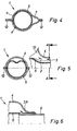
- the silencer partially shown in Figures 4 to 6 So has a completely prefabricated silencer body 1 in the form of an inner tube 5, which of the two outer half-shells 4 is surrounded, with inner tube 5 and Outer shells 4 by a fold 12 in the area of the outer shells 4 are firmly connected to one another in an axial central region is located between the inner tube 5 and the outer shells 4 a cavity 13 to be filled with glass wool 2.
- the filling opening 3 can be designed differently.
- the filling opening 3 can be in the outer shell 4 trained bore, which after insertion of the Glass wool is closed again, e.g. through a welded Closure 10 in the form of a on the outer shell 4th welded plug, as shown in Figure 1, or by a riveted closure 11, as shown in FIG 2 is illustrated.
- the filling opening can also be through a U-shaped incision be produced in the outer shell 4, as in Figure 3 is shown. After a cut, the cut one Section 6 deformed or bent to ultimately form the filling opening 3. After an introduction the glass wool 2, the bent section 6 is shaped back again and welded.
- the filling opening 3 can be deformed by the Outer shells 4 in the area of an axial end of the outer shells 4 be formed so that a gap 7 or a filler channel according to Figure 4 arises through which glass wool 2 in the Muffler interior can be introduced.
- the glass wool becomes the deformation of the two outer shells 4 reshaped by pressing together of the two outer shells in the area there, so that the Gap 7 or the filling channel is closed again. Possibly becomes the bent area of the two half-shells still spot or seam welded to a flawless Establish tightness and strength of the silencer.
- the outer shells 5 are deformed around the filling opening 3 to train. After filling the glass wool the deformed inner tube 5 is bent back exactly round, around the filling opening at the axial end of the outer shells 4 close again.
- the inner shell or the inner tube 5 have a hole 3 or 8 or a perforation on the shell side, which are used to fill the cavity 13 with glass wool 2 can be used.
- the hole or the jacket perforation is closed again after filling by an intermediate pipe 9 coaxially inserted into the inner tube 5 tightly and is fixed axially.
- Last hole 8 can also as a pressure compensation hole when filling one other filling opening can be used.
- filling opening 3 on the outer shell 4 on the jacket side according to FIGS. 1, 2 or 3 or on the front side can be designed according to Figure 4. Furthermore can the filling opening 3 on the inner shell or in the inner tube 5 jacket side according to FIG. 6 or front side according to FIG. 5 be located.
- the invention allows despite the complete construction of the silencer body even internal cavities that are difficult to access 13 satisfactory and easy to retrofit with glass wool be packed.
- a shell muffler is shown in FIGS. 7 and 8, which has such cavities 13 at the same time or one after the other through two or one filler pipe 15 on the end face and can be filled on the shell side.
- FIGS. which also has several (here front) filling openings has, through which filling through filler tubes 15 or packing cavities 13 is possible.
Landscapes
- Engineering & Computer Science (AREA)
- Chemical & Material Sciences (AREA)
- Combustion & Propulsion (AREA)
- Mechanical Engineering (AREA)
- General Engineering & Computer Science (AREA)
- Exhaust Silencers (AREA)
Abstract
Description
- Fig. 1
- eine Einfüllöffnung in einer Außenschale eines Schalldämpfers in Halbschalenbauweise mit einem verschweißten Verschluß in Form eines angeschweißten Stopfens,
- Fig. 2
- eine Einfülloffnung wie in Figur 1 mit einem vernieteten Verschluß,
- Fig. 3
- eine dritte Einfüllöffnung in Form eines aufgebogenen Einschnitts in der Außenschale des Schalldämpferkörpers,
- Fig. 4
- einen Schalldämpferkörper in einem Querschnitt mit Ausbildung eines Einfüllkanals bzw. Spalts im Bereich der Außenschale,
- Fig. 5
- den Schalldämpferkörper nach Figur 4 in einem Querschnitt, links, längs A-A des Längsteilschnitts, rechts, mit Ausbildung eines Einfüllkanals bzw. Spalts im Bereich der Innenschale bzw. des Innenrohrs durch Verformung des Innenrohrs,
- Fig. 6
- einen Axialteilschnitt durch einen Schalldämpferkörper in anderer Ausführungsvariante,
- Fig. 7
- einen Schalldämpfer in Schalenbauweise in aufgebrochener Seitenansicht mit Darstellung zweier Einfüllrohre,
- Fig. 8
- den Schalldämpfer nach Fig. 7 in einem schematischen Querschnitt im Bereich der Einfüllrohre,
- Fig. 9
- einen Schalldämpfer in Wickelbauweise in einem schematischen Längsquerschnitt mit Darstellung zweier Einfüllrohre, und
- Fig. 10
- den Schalldämpfer nach Fig. 9 in einer Stirnansicht.
Claims (15)
- Verfahren zur Herstellung eines Absorptions-Schalldämpfers für Kraftfahrzeuge mit einem in einem Hohlraum (13) des Schalldämpferkörpers (1) angeordneten Schalldämpfungsmaterial in Form von Glaswolle (2), welche als expandiertes endloses Glasfaservorgespinst in den Hohlraum (13) eingebracht wird,
dadurch gekennzeichnet,
daß der Schalldämpferkörper (1) komplett vorgefertigt und zusammengesetzt wird, und daß die Glaswolle (2) in den vorgefertigten, zusammengesetzten Schalldämpferkörper (1) nachträglich von außen eingebracht wird. - Verfahren nach Anspruch 1,
dadurch gekennzeichnet,
daß die Glaswolle (2) mittels zumindest eines starren Einfüllrohres (15) oder eines flexiblen Einfüllschlauches über eine oder mehrere im Schalldämpferkörper (1) ausgebildete Einfüllöffnungen (3) eingebracht wird, wobei das Einfüllrohr (15) oder der Einfüllschlauch nach einem Einbringen der Glaswolle (2) aus der Einfüllöffnung wieder entfernt wird. - Verfahren nach Anspruch 2,
dadurch gekennzeichnet,
daß die Glaswolle (2) unter Druck durch das Einfüllrohr (15) oder den Einfüllschlauch in den Hohlraum (13) des Schalldämpferkörpers (1) eingepreßt und/oder durch ein Vakuum im Innern des Schalldämpferkörpers angesaugt wird. - Verfahren nach Anspruch 2 oder 3,
dadurch gekennzeichnet,
daß die Einfüllöffnungen (3) vor oder nach einem Zusammensetzen eines Schalldämpferkörpers (1) ausgebildet und nach einem Einbringen der Glaswolle (2) geschlossen werden. - Verfahren nach Anspruch 4,
dadurch gekennzeichnet,
daß die Außenhaut oder Außenschale (4) des Schalldämpferkörpers (1) für eine Ausbildung der Einfüllöffnung (3) eingeschnitten, und daß der eingeschnittene Abschnitt (6) verformt und nach einem Einbringen der Glaswolle (2) wieder zurückgeformt und gegebenenfalls verschweißt wird (Fig. 3). - Verfahren nach Anspruch 4 oder 5,
dadurch gekennzeichnet,
daß ein stirnseitiger Einfüllspalt (7) zwischen einem Innenrohr (5) und einer endseitig ausgebauchten Außenhaut bzw. Außenschale (4) eines Schalldämpferkörpers (1) nach einem Einbringen der Glaswolle (2) wieder zugedrückt und gegebenenfalls verschweißt wird (Fig. 4). - Verfahren nach einem der Ansprüche 1 bis 6,
dadurch gekennzeichnet,
daß ein endseitig teilweise auf dem Umfang verformtes Innenrohr (5) nach einem Einbringen der Glaswolle (2) wieder zurückgeformt wird (Fig. 5). - Verfahren nach einem der Ansprüche 1 bis 7,
dadurch gekennzeichnet,
daß nach einem Einbringen der Glaswolle (2) in den Hohlraum des Schalldämpferkörper (1) ein Loch (8) oder eine Mantelperforation in der Innenschale bzw. im Innenrohr (5) durch Einschieben eines Zwischenrohrs (9) in die Innenschale bzw. in das Innenrohr (5) wieder verschlossen wird (Fig. 6). - Absorptions-Schalldämpfer in Halbschalen- oder Wickelbauweise, gefertigt nach einem der Verfahren gemäß Anspruch 1 bis 9,
dadurch gekennzeichnet,
daß im komplett vorgefertigten, zusammengesetzten Schalldämpferkörper (1) nachträglich von außen eingebrachte Glaswolle (2) vorgesehen ist. - Schalldämpfer nach Anspruch 9,
dadurch gekennzeichnet,
daß die Außenhaut bzw. Außenschale (4) zumindest eine Einfüllöffnung (3) aufweist, durch welche die Glaswolle (2) in den zusammengesetzten, vorgefertigten Schalldämpferkörper (1) nachträglich eingebracht worden und welche nach einem Einbringen der Glaswolle verschlossen ist. - Schalldämpfer nach Anspruch 9 oder 10,
dadurch gekennzeichnet,
daß die Einfüllöffnung (3) eines nachträglich mit Glaswolle (2) versehenen Schalldämpferkörpers (1) einen verschweißten Verschluß (10) in Form eines angeschweißten Stopfens aufweist (Fig. 1). - Schalldämpfer nach Anspruch 9 oder 10,
dadurch gekennzeichnet,
daß die Einfüllöffnung (3) eines nachträglich mit Glaswolle (2) versehenen Schalldämpferkörpers (1) einen vernieteten Verschluß (11) aufweist (Fig. 2). - Schalldämpfer nach einem der Ansprüche 9 bis 12,
dadurch gekennzeichnet,
daß der mit Glaswolle (2) versehene Schalldämpferkörper (1) eine angepreßte Außenschale (4) bzw. zumindest teilweise zusammengedrückte Außenschale aufweist, welche gegebenenfalls noch verschweißt ist (Fig. 4). - Schalldämpfer nach einem der Ansprüche 9 bis 13,
dadurch gekennzeichnet,
daß eine stirnseitig auf dem Umfang zumindest teilweise verformte Innenschale bzw. ein verformtes Innenrohr (5) eines mit Glaswolle (2) versehenen Schalldämpferkörpers (1) zurückgeformt ist (Fig. 5). - Schalldämpfer nach einem der Ansprüche 9 bis 14,
dadurch gekennzeichnet,
daß die Innenschale bzw. das Innenrohr (5) des Schalldämpferkörpers (1) ein Loch (8) oder eine Mantelperforation aufweist, welche nach einem Einbringen der Glaswolle (2) durch ein eingeschobenes Zwischenrohr (9) verschlossen ist (Fig. 6).
Applications Claiming Priority (4)
| Application Number | Priority Date | Filing Date | Title |
|---|---|---|---|
| DE19757810 | 1997-12-24 | ||
| DE19757810 | 1997-12-24 | ||
| DE19811192 | 1998-03-14 | ||
| DE19811192A DE19811192A1 (de) | 1997-12-24 | 1998-03-14 | Verfahren zur Herstellung eines Absorptions-Schalldämpfers |
Publications (3)
| Publication Number | Publication Date |
|---|---|
| EP0926320A2 true EP0926320A2 (de) | 1999-06-30 |
| EP0926320A3 EP0926320A3 (de) | 2003-01-02 |
| EP0926320B1 EP0926320B1 (de) | 2006-05-24 |
Family
ID=26042829
Family Applications (1)
| Application Number | Title | Priority Date | Filing Date |
|---|---|---|---|
| EP98117027A Expired - Lifetime EP0926320B1 (de) | 1997-12-24 | 1998-09-09 | Verfahren zur Herstellung eines Absorptions-Schalldämpfers |
Country Status (3)
| Country | Link |
|---|---|
| US (1) | US6158547A (de) |
| EP (1) | EP0926320B1 (de) |
| DE (1) | DE59813552D1 (de) |
Cited By (4)
| Publication number | Priority date | Publication date | Assignee | Title |
|---|---|---|---|---|
| WO2002006643A3 (en) * | 2000-07-18 | 2002-06-27 | Owens Corning Fiberglass Corp | A multiple layer fiber filled sound absorber and a method of manufacturing the same |
| WO2002060763A3 (en) * | 2001-02-01 | 2002-11-21 | Owens Corning Composites Sprl | Fibrous material filled muffler and its filling |
| US8590155B2 (en) | 2009-06-03 | 2013-11-26 | Ocv Intellectual Capital, Llc | Apparatus for and process of filling a muffler with fibrous material utilizing a directional jet |
| WO2016145244A1 (en) * | 2015-03-11 | 2016-09-15 | Ocv Intellectual Capital, Llc | Methods and systems for filling mufflers with fibrous material |
Families Citing this family (21)
| Publication number | Priority date | Publication date | Assignee | Title |
|---|---|---|---|---|
| US6317959B1 (en) * | 1999-02-16 | 2001-11-20 | Owens Corning Sweden A.B. | Process and apparatus for packing insulation material in a passage between first and second elements |
| EP1332071B1 (de) | 2000-11-07 | 2008-09-10 | Owens Corning | Stossstangen / schalldämpferanordnung |
| US6467571B2 (en) * | 2000-12-11 | 2002-10-22 | Nakagawa Sangyo Co., Ltd. | Sound absorbing material, muffler using the sound absorbing material, and method for forming sound absorbing layer thereof |
| US6446750B1 (en) | 2001-03-16 | 2002-09-10 | Owens Corning Fiberglas Technology, Inc. | Process for filling a muffler shell with fibrous material |
| US6581723B2 (en) | 2001-08-31 | 2003-06-24 | Owens Corning Composites Sprl | Muffler shell filling process, muffler filled with fibrous material and vacuum filling device |
| US6607052B2 (en) | 2001-09-12 | 2003-08-19 | Owens Corning Composites Sprl | Muffler shell filling process and muffler filled with fibrous material |
| US7077922B2 (en) | 2003-07-02 | 2006-07-18 | Owens Corning Composites S.P.R.L. | Technique to fill silencers |
| DE102006016096B3 (de) * | 2006-04-04 | 2007-12-13 | J. Eberspächer GmbH & Co. KG | Bauteilanordnung und zugehöriges Herstellungsverfahren |
| US7942237B2 (en) | 2006-04-12 | 2011-05-17 | Ocv Intellectual Capital, Llc | Long fiber thermoplastic composite muffler system with integrated reflective chamber |
| US7934580B2 (en) | 2006-04-12 | 2011-05-03 | Ocv Intellectual Capital, Llc | Long fiber thermoplastic composite muffler system |
| FR2911165B1 (fr) * | 2007-01-10 | 2010-01-22 | Faurecia Sys Echappement | Procede pour la fabrication d'un element d'echappement d'une ligne d'echappement d'un vehicule a moteur thermique et element d'echappement, notamment obtenu par la mise en oeuvre de ce procede |
| DE102007010814A1 (de) * | 2007-03-06 | 2008-09-11 | Arvinmeritor Emissions Technologies Gmbh | Schalldämpfer-Dämmelement, Schalldämpfer sowie Verfahren zur Herstellung eines Schalldämpfers |
| DE102007027372A1 (de) * | 2007-06-11 | 2008-12-18 | Cognis Oleochemicals Gmbh | Verfahren zur Hydrierung von Glycerin |
| US7975382B2 (en) * | 2007-10-30 | 2011-07-12 | Ocv Intellectual Capital, Llc | Method for filling a muffler cavity |
| US20100307863A1 (en) * | 2007-12-14 | 2010-12-09 | Ocv Intellectual Capital, Llc | Composite muffler system thermosetable polymers |
| US8474115B2 (en) | 2009-08-28 | 2013-07-02 | Ocv Intellectual Capital, Llc | Apparatus and method for making low tangle texturized roving |
| CN103925053A (zh) * | 2013-01-14 | 2014-07-16 | 三河三友汽车部件有限公司 | 车用消音器的制造方法 |
| DE102016106125A1 (de) * | 2016-04-04 | 2017-10-05 | Faurecia Emissions Control Technologies, Germany Gmbh | Isoliervorrichtung für eine Abgasanlage, Abgasanlage und Verfahren zur Herstellung einer Isoliervorrichtung |
| MX2020013414A (es) * | 2018-10-12 | 2021-02-26 | Crefact Co Ltd | Metodo y aparato para llenar un silenciador con fibra de vidrio. |
| JP7195183B2 (ja) * | 2019-03-06 | 2022-12-23 | 三恵技研工業株式会社 | 消音器及びその製造方法 |
| JP7260511B2 (ja) * | 2020-08-07 | 2023-04-18 | 株式会社ユタカ技研 | 消音器への吸音材充填方法 |
Citations (1)
| Publication number | Priority date | Publication date | Assignee | Title |
|---|---|---|---|---|
| EP0091413A2 (de) | 1982-04-06 | 1983-10-12 | Scandinavian Glasfiber AB | Behälter durch den ein Gas fliesst, vorzugsweise ein Dämpfer, mit Glasfaserfüllung und Verfahren und Vorrichtung zum Füllen |
Family Cites Families (2)
| Publication number | Priority date | Publication date | Assignee | Title |
|---|---|---|---|---|
| DE3476241D1 (en) * | 1983-11-18 | 1989-02-23 | Tba Industrial Products Ltd | Glass fibre products |
| JPH0526025A (ja) * | 1991-07-17 | 1993-02-02 | Osaka Tanshiya Yohin Kogyo Kk | 排気消音器 |
-
1998
- 1998-09-09 DE DE59813552T patent/DE59813552D1/de not_active Expired - Lifetime
- 1998-09-09 EP EP98117027A patent/EP0926320B1/de not_active Expired - Lifetime
- 1998-12-22 US US09/218,222 patent/US6158547A/en not_active Expired - Lifetime
Patent Citations (1)
| Publication number | Priority date | Publication date | Assignee | Title |
|---|---|---|---|---|
| EP0091413A2 (de) | 1982-04-06 | 1983-10-12 | Scandinavian Glasfiber AB | Behälter durch den ein Gas fliesst, vorzugsweise ein Dämpfer, mit Glasfaserfüllung und Verfahren und Vorrichtung zum Füllen |
Cited By (8)
| Publication number | Priority date | Publication date | Assignee | Title |
|---|---|---|---|---|
| WO2002006643A3 (en) * | 2000-07-18 | 2002-06-27 | Owens Corning Fiberglass Corp | A multiple layer fiber filled sound absorber and a method of manufacturing the same |
| US6543576B1 (en) | 2000-07-18 | 2003-04-08 | Owens-Corning Fiberglas Technology, Inc. | Multiple layer fiber filled sound absorber and a method of manufacturing the same |
| WO2002060763A3 (en) * | 2001-02-01 | 2002-11-21 | Owens Corning Composites Sprl | Fibrous material filled muffler and its filling |
| US8590155B2 (en) | 2009-06-03 | 2013-11-26 | Ocv Intellectual Capital, Llc | Apparatus for and process of filling a muffler with fibrous material utilizing a directional jet |
| WO2016145244A1 (en) * | 2015-03-11 | 2016-09-15 | Ocv Intellectual Capital, Llc | Methods and systems for filling mufflers with fibrous material |
| CN107407187A (zh) * | 2015-03-11 | 2017-11-28 | Ocv智识资本有限责任公司 | 用于以纤维材料填充消音器的方法和系统 |
| US10525495B2 (en) | 2015-03-11 | 2020-01-07 | Ocv Intellectual Capital, Llc | Methods and systems for filling mufflers with fibrous material |
| CN107407187B (zh) * | 2015-03-11 | 2020-01-17 | Ocv智识资本有限责任公司 | 用于以纤维材料填充消音器的方法和系统 |
Also Published As
| Publication number | Publication date |
|---|---|
| EP0926320B1 (de) | 2006-05-24 |
| EP0926320A3 (de) | 2003-01-02 |
| DE59813552D1 (de) | 2006-06-29 |
| US6158547A (en) | 2000-12-12 |
Similar Documents
| Publication | Publication Date | Title |
|---|---|---|
| EP0926320B1 (de) | Verfahren zur Herstellung eines Absorptions-Schalldämpfers | |
| EP0919703B1 (de) | Verfahren zur Herstellung eines luftspaltisolierten Abgaskrümmers einer Fahrzeugabgasanlage | |
| DE4019899C1 (de) | ||
| DE69505924T2 (de) | Hohlgegenstand aus Kunststoff mit einem Schalldämpfer und Verfahren zur Herstellung | |
| EP0665365A2 (de) | Verfahren zum Vereinigen eines Abgasbehandlungskörpers mit seinem Gehäuse und Abgasbehandlungsvorrichtung | |
| DE19514020A1 (de) | Abgassammelrohr, insbesondere für eine Brennkraftmaschine in einem Kraftfahrzeug, und Verfahren zu dessen Herstellung | |
| DE4121525A1 (de) | Schalldaempfer mit einstueckigem gehaeuse | |
| EP2375017B1 (de) | Verfahren zur Herstellung eines Fahrzeugschalldämpfers und Fahrzeugschalldämpfer | |
| WO2021180436A1 (de) | Tankbehälter zur speicherung von gasen und verfahren zu dessen herstellung | |
| EP4098851B1 (de) | Schalldämpfer | |
| DE4004072A1 (de) | Doppelwandhohlkoerper mit zwischenlage und verfahren zur herstellung desselben | |
| DE102004039776A1 (de) | Schalldämpfer sowie zugehöriges Herstellungsverfahren | |
| EP1325216B1 (de) | Verfahren zur herstellung eines absorptions-schalldämpfers für kraftfahrzeuge sowie absorptions-schalldämpfer | |
| EP0870910B1 (de) | Abgasreinigungsvorrichtung | |
| DE19811192A1 (de) | Verfahren zur Herstellung eines Absorptions-Schalldämpfers | |
| DE102005009045B4 (de) | Verfahren und Vorrichtung zum Einbringen von Dämmfasern in einen Schalldämpfer sowie Schalldämpfer mit eingebrachten Dämmfasern | |
| EP1138408A2 (de) | Verfahren zur Herstellung von grossvolumigen Hohlkörpern | |
| EP4108890B1 (de) | Verfahren zur herstellung eines schalldämpfers und entsprechender schalldämpfer | |
| DE19548224A1 (de) | Verfahren zur Herstellung eines Rohrteiles, insbesondere einer Krümmer-Rohrabzweigung einer Kraftfahrzeug-Abgasanlage, sowie eine hiernach gefertigte Krümmer-Rohrabzweigung | |
| DE3304809A1 (de) | Formteil aus mit bindemittel versehenen mineralfasern zur schalldaempfenden umkleidung eines perforierten abgasrohres, sowie verfahren zu seiner herstellung | |
| EP0764756A1 (de) | Verbundprofil sowie Verfahren zur Herstellung desselben | |
| EP1111207A2 (de) | Verfahren zur Herstellung eines Absorptions-Schalldämpfers | |
| DE19857445B4 (de) | Verfahren zur Herstellung eines luftspaltisolierten Abgasrohres | |
| DE10226605A1 (de) | Verfahren zum Umformen eines Kaminrohrstücks und Kaminrohrstück | |
| EP1074703A1 (de) | Verfahren zur Herstellung eines Katalysators, insbesondere Vorfertigung eines Katalysatormantels bzw. -rohrs in Modulbauweise sowie hiernach gefertigtes Rohr |
Legal Events
| Date | Code | Title | Description |
|---|---|---|---|
| PUAI | Public reference made under article 153(3) epc to a published international application that has entered the european phase |
Free format text: ORIGINAL CODE: 0009012 |
|
| AK | Designated contracting states |
Kind code of ref document: A2 Designated state(s): AT BE CH CY DE DK ES FI FR GB GR IE IT LI LU MC NL PT SE |
|
| AX | Request for extension of the european patent |
Free format text: AL;LT;LV;MK;RO;SI |
|
| RAP1 | Party data changed (applicant data changed or rights of an application transferred) |
Owner name: J. EBERSPAECHER GMBH & CO. KG |
|
| PUAL | Search report despatched |
Free format text: ORIGINAL CODE: 0009013 |
|
| AK | Designated contracting states |
Kind code of ref document: A3 Designated state(s): AT BE CH CY DE DK ES FI FR GB GR IE IT LI LU MC NL PT SE |
|
| AX | Request for extension of the european patent |
Free format text: AL;LT;LV;MK;RO;SI |
|
| 17P | Request for examination filed |
Effective date: 20021121 |
|
| AKX | Designation fees paid |
Designated state(s): DE FR GB IT SE |
|
| 17Q | First examination report despatched |
Effective date: 20050518 |
|
| GRAP | Despatch of communication of intention to grant a patent |
Free format text: ORIGINAL CODE: EPIDOSNIGR1 |
|
| GRAS | Grant fee paid |
Free format text: ORIGINAL CODE: EPIDOSNIGR3 |
|
| GRAA | (expected) grant |
Free format text: ORIGINAL CODE: 0009210 |
|
| AK | Designated contracting states |
Kind code of ref document: B1 Designated state(s): DE FR GB IT SE |
|
| REG | Reference to a national code |
Ref country code: GB Ref legal event code: FG4D Free format text: NOT ENGLISH |
|
| REF | Corresponds to: |
Ref document number: 59813552 Country of ref document: DE Date of ref document: 20060629 Kind code of ref document: P |
|
| REG | Reference to a national code |
Ref country code: SE Ref legal event code: TRGR |
|
| GBT | Gb: translation of ep patent filed (gb section 77(6)(a)/1977) |
Effective date: 20060913 |
|
| ET | Fr: translation filed | ||
| PLBE | No opposition filed within time limit |
Free format text: ORIGINAL CODE: 0009261 |
|
| STAA | Information on the status of an ep patent application or granted ep patent |
Free format text: STATUS: NO OPPOSITION FILED WITHIN TIME LIMIT |
|
| 26N | No opposition filed |
Effective date: 20070227 |
|
| REG | Reference to a national code |
Ref country code: FR Ref legal event code: PLFP Year of fee payment: 18 |
|
| REG | Reference to a national code |
Ref country code: FR Ref legal event code: PLFP Year of fee payment: 19 |
|
| REG | Reference to a national code |
Ref country code: FR Ref legal event code: PLFP Year of fee payment: 20 |
|
| PGFP | Annual fee paid to national office [announced via postgrant information from national office to epo] |
Ref country code: DE Payment date: 20170921 Year of fee payment: 20 Ref country code: FR Payment date: 20170925 Year of fee payment: 20 Ref country code: IT Payment date: 20170926 Year of fee payment: 20 Ref country code: GB Payment date: 20170925 Year of fee payment: 20 |
|
| PGFP | Annual fee paid to national office [announced via postgrant information from national office to epo] |
Ref country code: SE Payment date: 20170925 Year of fee payment: 20 |
|
| REG | Reference to a national code |
Ref country code: DE Ref legal event code: R071 Ref document number: 59813552 Country of ref document: DE |
|
| REG | Reference to a national code |
Ref country code: GB Ref legal event code: PE20 Expiry date: 20180908 |
|
| PG25 | Lapsed in a contracting state [announced via postgrant information from national office to epo] |
Ref country code: GB Free format text: LAPSE BECAUSE OF EXPIRATION OF PROTECTION Effective date: 20180908 |