EP0926339A2 - Revêtement d'un joint pivotable d'un plateau en biais - Google Patents
Revêtement d'un joint pivotable d'un plateau en biais Download PDFInfo
- Publication number
- EP0926339A2 EP0926339A2 EP98124480A EP98124480A EP0926339A2 EP 0926339 A2 EP0926339 A2 EP 0926339A2 EP 98124480 A EP98124480 A EP 98124480A EP 98124480 A EP98124480 A EP 98124480A EP 0926339 A2 EP0926339 A2 EP 0926339A2
- Authority
- EP
- European Patent Office
- Prior art keywords
- drive shaft
- cam plate
- swash plate
- support portion
- compressor
- Prior art date
- Legal status (The legal status is an assumption and is not a legal conclusion. Google has not performed a legal analysis and makes no representation as to the accuracy of the status listed.)
- Withdrawn
Links
- 239000011248 coating agent Substances 0.000 title claims description 4
- 238000000576 coating method Methods 0.000 title claims description 4
- 238000006073 displacement reaction Methods 0.000 claims abstract description 56
- 230000007246 mechanism Effects 0.000 claims abstract description 41
- 239000011247 coating layer Substances 0.000 claims abstract description 26
- 230000008859 change Effects 0.000 claims description 11
- 238000007747 plating Methods 0.000 claims description 3
- 229920000642 polymer Polymers 0.000 claims description 3
- 239000012530 fluid Substances 0.000 description 25
- 230000033001 locomotion Effects 0.000 description 11
- 239000003507 refrigerant Substances 0.000 description 10
- 230000006835 compression Effects 0.000 description 7
- 238000007906 compression Methods 0.000 description 7
- CNQCVBJFEGMYDW-UHFFFAOYSA-N lawrencium atom Chemical compound [Lr] CNQCVBJFEGMYDW-UHFFFAOYSA-N 0.000 description 5
- 238000004378 air conditioning Methods 0.000 description 4
- 238000006243 chemical reaction Methods 0.000 description 4
- 230000007423 decrease Effects 0.000 description 4
- 230000003247 decreasing effect Effects 0.000 description 4
- 238000012544 monitoring process Methods 0.000 description 4
- 238000000605 extraction Methods 0.000 description 3
- 230000005484 gravity Effects 0.000 description 3
- 230000004044 response Effects 0.000 description 3
- 230000015572 biosynthetic process Effects 0.000 description 2
- 238000003754 machining Methods 0.000 description 2
- 238000004519 manufacturing process Methods 0.000 description 2
- 229920001343 polytetrafluoroethylene Polymers 0.000 description 2
- 239000004810 polytetrafluoroethylene Substances 0.000 description 2
- 230000009467 reduction Effects 0.000 description 2
- ATJFFYVFTNAWJD-UHFFFAOYSA-N Tin Chemical compound [Sn] ATJFFYVFTNAWJD-UHFFFAOYSA-N 0.000 description 1
- 238000005553 drilling Methods 0.000 description 1
- 230000000694 effects Effects 0.000 description 1
- 238000003801 milling Methods 0.000 description 1
- 230000004048 modification Effects 0.000 description 1
- 238000012986 modification Methods 0.000 description 1
- 230000002093 peripheral effect Effects 0.000 description 1
- -1 polytetrafluoroethylene Polymers 0.000 description 1
- 230000001105 regulatory effect Effects 0.000 description 1
- 239000013589 supplement Substances 0.000 description 1
Images

Classifications
-
- F—MECHANICAL ENGINEERING; LIGHTING; HEATING; WEAPONS; BLASTING
- F04—POSITIVE - DISPLACEMENT MACHINES FOR LIQUIDS; PUMPS FOR LIQUIDS OR ELASTIC FLUIDS
- F04B—POSITIVE-DISPLACEMENT MACHINES FOR LIQUIDS; PUMPS
- F04B27/00—Multi-cylinder pumps specially adapted for elastic fluids and characterised by number or arrangement of cylinders
- F04B27/08—Multi-cylinder pumps specially adapted for elastic fluids and characterised by number or arrangement of cylinders having cylinders coaxial with, or parallel or inclined to, main shaft axis
- F04B27/10—Multi-cylinder pumps specially adapted for elastic fluids and characterised by number or arrangement of cylinders having cylinders coaxial with, or parallel or inclined to, main shaft axis having stationary cylinders
- F04B27/1036—Component parts, details, e.g. sealings, lubrication
- F04B27/1054—Actuating elements
- F04B27/1072—Pivot mechanisms
-
- F—MECHANICAL ENGINEERING; LIGHTING; HEATING; WEAPONS; BLASTING
- F05—INDEXING SCHEMES RELATING TO ENGINES OR PUMPS IN VARIOUS SUBCLASSES OF CLASSES F01-F04
- F05C—INDEXING SCHEME RELATING TO MATERIALS, MATERIAL PROPERTIES OR MATERIAL CHARACTERISTICS FOR MACHINES, ENGINES OR PUMPS OTHER THAN NON-POSITIVE-DISPLACEMENT MACHINES OR ENGINES
- F05C2225/00—Synthetic polymers, e.g. plastics; Rubber
- F05C2225/04—PTFE [PolyTetraFluorEthylene]
-
- F—MECHANICAL ENGINEERING; LIGHTING; HEATING; WEAPONS; BLASTING
- F05—INDEXING SCHEMES RELATING TO ENGINES OR PUMPS IN VARIOUS SUBCLASSES OF CLASSES F01-F04
- F05C—INDEXING SCHEME RELATING TO MATERIALS, MATERIAL PROPERTIES OR MATERIAL CHARACTERISTICS FOR MACHINES, ENGINES OR PUMPS OTHER THAN NON-POSITIVE-DISPLACEMENT MACHINES OR ENGINES
- F05C2253/00—Other material characteristics; Treatment of material
- F05C2253/12—Coating
Definitions
- the present invention relates generally to a compressor and, more particularly, to a variable displacement compressor which can optimize a compression ratio of a hydraulic fluid and adjust a compressor displacement.
- variable displacement compressor which can optimize a compression ratio of a hydraulic fluid and adjust a compressor displacement by varying a stroke of a piston in the compressor has been well known in the art, and is commonly used as a refrigerant compressor in an air conditioning system of, e.g., a vehicle.
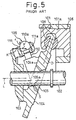
- One example of conventional variable displacement compressors is disclosed in Japanese Unexamined Patent Publication (Kokai) No. 7-91366 (JP-A-7-91366), and Fig. 5 shows the main parts of this example.
- the variable displacement compressor disclosed in JP-A-7-91366 includes a housing 101, a drive shaft 102 rotatably supported in the housing 101, a rotor element 103 fixed on the drive shaft 102 for rotation together with the drive shaft 102, a swash plate 104 as a cam plate carried on the drive shaft 102, and plural single headed pistons 106 (only one piston 106 is shown) housed inside respective cylinder bores 101a (only one cylinder bore 101a is shown).
- the swash plate 104 is provided with a center through hole 105 through which the drive shaft 102 extends, and is operatively connected with the rotor element 103 through a joint mechanism 109.
- the swash plate 104 is also operatively engaged with the pistons 106 through respective pairs of hemispherical shoes 108 to reciprocate the pistons 106 in the cylinder bores 101a due to the rotation of the swash plate 104.
- the joint mechanism 109 includes a guide pin 110 formed on the swash plate 104 to project obliquely from a front surface 104a (or a left surface in the figure) of the swash plate 104.
- the guide pin 110 is substantially located along a certain radius line "D" of the swash plate 104, the radius line "D" being specified so that one piston 106 is positioned at a top dead center thereof when the swash plate 104 is engaged with this piston 106 along the radius line "D".
- the guide pin 110 is provided at the distal end thereof with a generally spherical head 110a.
- the joint mechanism 109 also includes a support arm 111 formed on the rotor element 103 to project from the upper end portion of the rotor element 103 toward the swash plate 104.
- the support arm 110 is provided with a guide hole 111a, the axis of which extends obliquely in relation to a rotation axis "L" of the drive shaft 102.
- the guide pin 110 is inserted into the guide hole 111a, and the generally spherical head 110a of the guide pin 110 is slidably engaged with the inner wall surface of the guide hole 111a.
- the center through hole 105 of the swash plate 104 is provided with a support portion 105a on the inner wall surface of the center hole 105 to provide a slidable support for the swash plate 104 on the drive shaft 102.
- the support portion 105a is defined at a certain position opposite to the joint mechanism 109 in relation to the rotation axis "L" of the drive shaft 102.
- the support portion 105a is also formed at an apex of the inner wall surface of the center hole 105, and includes a generally arcuate surface extending about a lateral axis "S" in a vertical section as shown in Fig. 5.
- the swash plate 104 is operatively connected through the joint mechanism 109 and the rotor element 103 to the drive shaft 102 and thus can rotate together with the drive shaft 102 in the housing 101.
- the rotating motion of the swash plate 104 due to the rotation of the drive shaft 102 is converted to the reciprocating motion of the pistons 106 in the cylinder bores 101a in a direction parallel to the axis "L" of the shaft 102 through the sliding engagement in the shoes 108, so that a hydraulic fluid, such as a refrigerant, is intermittently compressed in the cylinder bores 101a.
- the swash plate 104 can also be shifted on the drive shaft 102 to change the inclination of the swash plate 104 relative to the rotation axis "L" of the shaft 102, under the slidable guide for the spherical head 110a of the guide pin 110 in the guide hole 111a of the support arm 111 in the joint mechanism 109, and also under the slidable support for the swash plate 104 on the drive shaft 102 at the support portion 105a in the swash plate center hole 105.
- the stroke of each piston 106 is varied, and thereby the compression ratio of the hydraulic fluid is optimized or the displacement of the compressor is adjusted.
- the piston 106 is subjected to a compressive load "K” due to the compression of the hydraulic fluid or refrigerant gas, and the compressive load “K” is applied to the inner wall surface of the guide hole 111a, on a front side (or a left side in the figure) away from the swash plate 104, through the shoes 108, the swash plate 104 and the head 110a of the guide pin 110. Then, the reaction force "F" is applied to the head 110a of the guide pin 110 from the inner wall surface of the guide hole 111a.
- the guide hole 111a extends obliquely relative to the axis "L" of the drive shaft 102, that is, one open end of the guide hole 111a opposed to the shaft 102 is located nearer the front surface 104a of the swash plate 104 than another open end of the guide hole 111a. Therefore, the reaction force "F" applied to the guide pin 110 acts to bias the swash plate 104 in a direction "f" toward the joint mechanism 109 in relation to the drive shaft 102. In this manner, during the operation of the compressor, the support portion 105a in the center hole 105 of the swash plate 104 is continuously urged onto the outer circumferential surface of the drive shaft 102.
- the swash plate 104 When the displacement of the compressor is adjusted, the swash plate 104 is shifted in a sliding manner on the drive shaft 102 to change the inclination of the swash plate 104 relative to the shaft 102, while the support portion 105a of the swash plate 104 is urged onto and slidably engaged with the outer circumferential surface of the shaft 102. In this shifting motion, the swash plate 104 is also tilted or rotated about the lateral axis "S" of the arcuate surface of the support portion 105a.
- the swash plate 104 is supported on and guided along the drive shaft 102 through the slidable support due to the support portion 105a in the center hole 105.
- This structure serves to reduce the number of parts, such as a sleeve slidably provided on the shaft and pivot pins formed on the sleeve to pivotably support the swash plate, which has been used for the slidable support between the drive shaft and the swash plate in the other conventional compressor (e.g., a compressor disclosed in Japanese Unexamined Patent Publication (Kokai) No. 4-159464), and thereby serves to decrease the production cost and to ease stock management.
- the support portion 105a of the swash plate 104 is firmly urged and contacted under pressure onto the outer circumferential surface of the drive shaft 102 during the operation of the compressor.
- the arcuate surface of the support portion 105a is formed by machining or milling the center hole 105 of the swash plate 104, and thereby a machined metallic surface is exposed on the support portion 105a.
- the machined surface of the support portion 105a has a relatively large coefficient of friction, and thus tends to increase a friction force caused between the drive shaft 102 and the support portion 105a during the shifting motion of the swash plate 104 to adjust the displacement. Consequently, it is difficult to smoothly shift or tilt the swash plate 104 on the drive shaft 102, which may deteriorate the responsibility of the adjustment of the compressor displacement.
- a variable displacement compressor comprising a housing assembly having at least one cylinder; a drive shaft rotatably supported in the housing assembly; a cam plate arranged in the housing assembly and provided at a generally center thereof with a through hole, through which the drive shaft extends, the cam plate being provided in a wall surface of the through hole with a support portion abutted onto the drive shaft to establish a slidable support for the cam plate on the drive shaft; a joint mechanism for connecting the cam plate with the drive shaft to rotate the cam plate together with the drive shaft, the joint mechanism permitting the cam plate to shift on the drive shaft to change an inclination of the cam plate relative to the drive shaft; at least one piston respectively accommodated in the at least one cylinder and engaged with the cam plate to be reciprocated in the cylinder due to a rotation of the cam plate; a control mechanism for changing the inclination of the cam plate on the drive shaft to adjust a compressor displacement; and a friction reducing means for reducing a friction force caused between the drive shaft
- the friction reducing means includes a coating layer provided on the wall surface of the through hole of the cam plate to coat the support portion therewith, the coating layer lowering a coefficient of friction of the support portion abutted onto the drive shaft.
- the coating layer has a coefficient of friction lower than that of the wall surface of the through hole.
- the coating layer may be formed by plating the wall surface of the through hole.
- the coating layer may be formed by coating the wall surface of the through hole with fluorine-contained polymers.
- the coating layer is formed substantially entirely on the wall surface of the through hole.
- the coating layer may be formed locally on the support portion.
- the support portion of the cam plate includes a generally arcuate surface extending about an axis located opposite to the joint mechanism in relation to the drive shaft.
- the drive shaft includes a flange portion rotating together with the drive shaft in the housing assembly
- the joint mechanism includes an arm extending from the cam plate to be slidably and pivotably engaged with the flange portion of the drive shaft and a guide member for guiding the arm on the flange portion in a direction permitting the cam plate to change the inclination on the drive shaft.
- the arm may include a guiding projection projecting from the arm, and the flange portion may include a guiding recess disposed frontward or backward of the arm in view of a rotation direction of the cam plate for receiving and guiding the guiding projection.
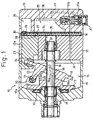
- Fig. 1 shows one embodiment of a variable displacement compressor 10 according to the present invention.
- the variable displacement compressor 10 of this embodiment may be used as a refrigerant compressor having single headed pistons, in an air conditioning system of, e.g., a vehicle.
- the variable displacement compressor 10 includes a housing assembly, a drive shaft 16 rotatably supported in the housing assembly, a rotor element 17 fixed on the drive shaft 16 for rotation together with the drive shaft 16, a swash plate 18 carried on the drive shaft 16, and plural single headed pistons 23 (only one piston 23 is shown) slidably fitted inside respective cylinder bores 12a (only one cylinder bore 12a is shown).
- the housing assembly includes a front housing 11, a cylinder block 12 and a rear housing 13, axially combined with each other.
- the front housing 11 is securely joined to a front end (a left end in the figure) of the cylinder block 12 to define a crank chamber 15 therebetween.
- the rear housing 13 is securely joined to a rear end (a right end in the figure) of the cylinder block 12 with a valve assembly 14 being held therebetween.
- the cylinder bores 12a are formed in the cylinder block 12 and are spaced in a circumferential direction with each other about a rotation axis "L" of the drive shaft 16.
- the drive shaft 16 extends through the crank chamber 15, and is rotatably supported by a front bearing 31 arranged in the front housing 11 and by a rear bearing 32 arranged in the cylinder block 12.
- the drive shaft 16 is connected at the front end thereof to an outside drive source, such as a vehicle engine (not shown), through a clutch mechanism, such as an electromagnetic clutch (not shown). Accordingly, the drive shaft 16 rotates when the clutch mechanism is actuated to connect the operating drive source to the drive shaft 16.
- the rotor element 17, as a flange portion, fixed on the drive shaft 16 is disposed inside the crank chamber 15, and is rotatably supported by a bearing 33 on the front housing 11 for rotation in the crank chamber 15.
- the swash plate 18, as a cam plate, is also disposed inside the crank chamber 15, and is provided generally at a center of the swash plate with a center through hole 19, through which the drive shaft 16 extends.
- the swash plate 18 is operatively connected with the rotor element 17 through a joint mechanism 20.
- the swash plate 18 is also operatively engaged at the outer peripheral region thereof with the pistons 23 through respective pairs of hemispherical shoes 24.
- the shoes 24 establish a slidable and tiltable engagement between the swash plate 18 and the pistons 23, so that the pistons 23 are reciprocated in the cylinder bores 12a due to the rotation of the swash plate 18.
- the center through hole 19 of the swash plate 18 is provided with a support portion 19a in the inner wall surface of the center hole 19 to provide a slidable support for the swash plate 18 on the drive shaft 16.
- the center through hole 19 is formed by certain steps as follows. First, a cylindrical bore is formed at the center of a swash plate workpiece by machining or drilling the workpiece. Then, an end mill having substantially the same diameter as the cylindrical bore is inserted into the bore, and is driven to machine the inner surface of the bore.
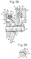
- the end mill is alternately tilted forward and backward about a lateral axis "S" in a range of a predetermined angle, the lateral axis "S” being defined at a certain position adapted to be opposite to the joint mechanism 20 in relation to the rotation axis "L” of the drive shaft 16 in a vertical section as shown in Fig. 2A.
- the support portion 19a including a generally arcuate surface extending about the lateral axis "S" is formed in the inner wall surface of the center hole 19 at a certain position adapted to be opposite to the joint mechanism 20 in relation to the rotation axis "L” of the drive shaft 16.
- the joint mechanism 20 includes a swing arm 43 formed on the swash plate 18 to project obliquely from a front surface 18b (or a left surface in the figure) of the swash plate 18.
- the swing arm 43 is substantially located along a certain radius line "D" of the swash plate 18, the radius line “D” being specified so that one piston 23 is positioned at a top dead center thereof when the swash plate 18 is engaged with this piston 23 along the radius line "D”.
- the swing arm 43 extends toward the rotor element 17 along the rotation axis "L”, and is provided at the distal end thereof with a through hole 43a extending perpendicularly to both the rotation axis "L” and the radius line "D".
- One guide pin 44 is press-fitted into the through hole 43a to be fixed to the swing arm 43. Both ends 44a of the guide pin 44 project from the lateral opposite surfaces of the swing arm 43.
- the joint mechanism 20 also includes a pair of support arms 45 formed on the rotor element 17 to project from the upper end portion of the rear surface 17a of the rotor element 17 toward the swash plate 18.
- the support arms 45 are located at symmetrical positions in relation to the radius line "D" of the swash plate 18.
- the swing arm 43 is inserted and arranged between the support arms 45, and the support arms 45 are disposed frontward and backward of the swing arm 43 in view of the rotation direction of the swash plate 18.
- Each support arm 45 is provided with a guide hole 45a shaped as an oblong hole.
- Each guide hole 45a extends obliquely in relation to the rotation axis "L" of the drive shaft 16, that is, one longitudinal end surface of the guide hole 45a opposed to the shaft 16 is located nearer the front surface 18a of the swash plate 18 than another longitudinal end surface of the guide hole 45a.
- the ends 44a of the guide pin 44 are respectively inserted into the corresponding guide holes 45a of the support arms 45, and the outer surface of the guide pin 110 is slidably engaged with the inner wall surfaces of the guide holes 45a.
- the joint mechanism 20 may include any guiding projection, in place of the guide pin 44, projecting from at least one lateral surface of the swing arm 43, and any guiding recess, in place of the guide holes 45a, formed in at least one support arm 45 disposed frontward or backward of the swing arm 43 in view of the rotation direction of the swash plate 18 for receiving the distal end of the guiding projection and guiding the latter.
- the joint mechanism 20 may be replaced by the joint mechanism 109 used in the conventional variable displacement compressor shown in Fig. 5.
- the joint mechanism 20 serves to further improve the response of the operation for adjusting the displacement of the compressor 10.
- a suction chamber 25 is defined between the rear housing 13 and the valve assembly 14 at a generally center region of the rear housing 13.
- a discharge chamber 26 is also defined between the rear housing 13 and the valve assembly 14 at a radially outer region of the rear housing 13.
- the valve assembly 14 includes a valve plate provided with plural suction ports 27 (only one suction port 27 is shown) for fluidly communicating the suction chamber 25 with the respective cylinder bores 12a, and plural discharge ports 29 (only one discharge port 29 is shown) for fluidly communicating the discharge chamber 26 with the respective cylinder bores 12a.
- the valve assembly 14 also includes a suction valve member 28 interposed between the valve plate and the cylinder block 12, and a discharge valve member 30 and a gasket 34, both interposed between the valve plate and the rear housing 13.
- the suction valve member 28 acts to selectively open/close the suction ports 27, and the discharge valve member 30 acts to selectively open/close the discharge ports 29.
- the gasket 34 is provided with plural valve retainers.
- the swash plate 18 is operatively connected through the joint mechanism 20 and the rotor element 17 to the drive shaft 16 and thus can rotate together with the drive shaft 16 in the crank chamber 15.
- the rotating motion of the swash plate 18 due to the rotation of the drive shaft 16 is converted to the reciprocating motion of the pistons 23 in the cylinder bores 12a in a direction parallel to the axis "L" of the shaft 16 through the sliding engagement in the shoes 24, so that hydraulic fluid, such as refrigerant gas, is intermittently compressed in the cylinder bores 12a.
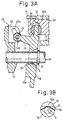
- Figs. 2A and 3A show such a condition that the swash plate 18 is engaged with one piston 23 along the radius line "D" and thereby this piston 23 is positioned at the top dead center thereof in the corresponding cylinder bore 12a.
- the illustrated piston 23 is positioned at a bottom dead center thereof.
- the hydraulic fluid such as refrigerant gas
- the suction chamber 25 is sucked through the corresponding suction port 27 and suction valve member 28 into the cylinder bore 12a.
- the hydraulic fluid inhaled into the cylinder bore 12a is compressed therein when the piston 23 is shifted from the bottom dead center to the top dead center, and is discharged through the corresponding discharge port 29 and discharge valve member 30 to the discharge chamber 26.
- the swash plate 18 can be shifted on the drive shaft 16 to change the inclination of the swash plate 18 relative to the rotation axis "L" of the shaft 16, under the slidable guide for the ends 44a of the guide pin 44 in the guide holes 45a of the support arms 45 in the joint mechanism 20, and also under the slidable support for the swash plate 18 on the drive shaft 16 at the support portion 19a in the swash plate center hole 19.
- an inclination angle of the swash plate 18, relative to a virtual plane orthogonal to the rotation axis "L” increases.
- the variable displacement compressor 10 further includes a control mechanism to automatically change the inclination angle of the swash plate 18 supported on the drive shaft 16 in response to the pressure change of the hydraulic fluid in a fluid circuit, such as a refrigerant circuit of the air conditioning system.
- the control mechanism includes an extraction passage 35, a supply passage 36, a control valve 37 and a monitoring passage 41.
- the extraction passage 35 is formed in the housing assembly, through which the crank chamber 15 is fluidly communicated with the suction chamber 25.
- the supply passage 36 is also formed in the housing assembly, through which the crank chamber 15 is fluidly communicated with the discharge chamber 26.
- the control valve 37 is supported on the rear housing 13, and is arranged in the supply passage 36 to selectively open and close the supply passage 36.
- the monitoring passage 41 is formed in the rear housing 13, through which the control valve 37 is connected with the suction chamber 15.
- the control valve 37 is a pressure sensitive valve which is actuated by the pressure change of the hydraulic fluid in the suction chamber 25 monitored through the monitoring passage 41.
- the control valve 37 includes a diaphragm 37a adapted to sense the pressure change in the suction chamber 25 through the monitoring passage 41, and a valve element 37b operatively connected to the diaphragm 37a.
- the aperture size of the supply passage 36 is adjusted by the control valve 37 so as to vary the internal pressure of the crank chamber 15, and thereby the difference between the pressure in the crank chamber 15 acting on the front sides (the left sides in the figure) of the pistons 23 and the pressure in the cylinder bores 12a acting on the rear sides (the right sides in the figure) of the pistons 23 is regulated.
- Such a pressure difference between the crank chamber 15 and the cylinder bores 12a affects the reciprocating motion or the stroke of the pistons 23.
- the inclination angle of the swash plate 18 supported on the drive shaft 16 is changed, the stroke of each piston 23 is varied, and thereby the compression ratio of the hydraulic fluid is optimized or the displacement of the compressor 10 is adjusted.
- the internal pressure in the crank chamber 15 and in the discharge chamber 26 are normally higher than the internal pressure in the suction chamber 25. If a load on the hydraulic fluid in the fluid circuit, such as the refrigerant in the refrigerant circuit, is enhanced so that the pressure of the hydraulic fluid in the suction chamber 25 rises above a set value, the control valve 37 is actuated so as to reduce the aperture size of the supply passage 36. Thereby, the internal pressure in the crank chamber 15 is relieved through the extraction passage 35 communicating with the suction chamber 25.
- the joint mechanism 20 operates in such a manner that the ends 44a of the guide pin 44 are moved along the guide holes 45a of the support arms 45 in a direction away from the rotation axis "L", and the swash plate 18 is tilted or rotated about the lateral axis "S" of the arcuate surface of the support portion 19a in a clockwise direction in the drawings.
- the swash plate 18 is shifted toward a position shown in Fig. 2A wherein the inclination angle of the swash plate 18 is maximum, and the stroke of each piston 23 is increased accordingly. Consequently, the displacement of the compressor 10 increases, and the pressure of the hydraulic fluid in the fluid circuit, or in the suction chamber 25, drops toward the set value.
- the control valve 37 is actuated so as to enlarge the aperture size of the supply passage 36.
- the internal pressure in the crank chamber 15 is increased due to the supply of the hydraulic fluid through the supply passage 36.
- the swash plate 18 is shifted in a sliding manner on the drive shaft 16 to decrease the inclination angle of the swash plate 18, while the support portion 19a of the swash plate 18 is urged onto and slidably engaged with the outer circumferential surface of the shaft 16.
- the joint mechanism 20 operates in such a manner that the ends 44a of the guide pin 44 are moved along the guide holes 45a of the support arms 45 in a direction toward the rotation axis "L", and the swash plate 18 is tilted or rotated about the lateral axis "S" of the arcuate surface of the support portion 19a in a counterclockwise direction in the drawings.
- the swash plate 18 is shifted toward a position shown in Fig. 3A wherein the inclination angle of the swash plate 18 is minimum, and the stroke of each piston 23 is reduced accordingly. Consequently, the displacement of the compressor 10 decreases, and the pressure of the hydraulic fluid in the fluid circuit, or in the suction chamber 25, rises toward the set value.
- each piston 23 is subjected to a compressive load "K” due to the compression of the hydraulic fluid or refrigerant gas, and the compressive load “K” is applied to the inner wall surfaces of the guide holes 45a of the support arms 45, on a front side (or a left side in the figure) away from the swash plate 18, through the shoes 24, the swash plate 18, the swing arm 43 and the guide pin 44.
- the reaction force "F” is applied to the guide pin 44 from the inner wall surfaces of the guide holes 45a.
- the guide holes 45a extend obliquely relative to the axis "L” of the drive shaft 16 as already described. Therefore, the reaction force "F” applied to the guide pin 44 acts to bias the swash plate 18 in a direction "f" toward the joint mechanism 20 in relation to the drive shaft 16.
- the compressive load "K” is reduced and the biasing force applied in the direction “f” is reduced accordingly.
- the reduction of the biasing force in the direction “f” may cause difficulties in keeping the support portion 19a of the swash plate 18 contacting the drive shaft 16.
- the swash plate 18 is structured so that the center of gravity thereof is displaced toward the joint mechanism 20 from the rotation axis "L”, so as to supplement the reduction of the biasing force during the lower displacement condition of the compressor 10.
- the center of gravity of the swash plate 18 is displaced mainly due to the eccentric location of swing arm 43 and guide pin 44 in relation to the rotation axis "L".
- the eccentric location of swing arm 43 and guide pin 44 can be compensated by forming a counter weight 18a on the swash plate 18 at the opposite side of the swing arm 43 in relation to the rotation axis "L".
- the counter weight 18a is positioned and dimensioned so that the center of gravity of the swash plate 18 is little displaced toward the joint mechanism 20 from the rotation axis "L”, so as to slightly unbalance the rotation of the swash plate 18. Accordingly, the rotating swash plate 18 is apt to be biased toward the joint mechanism 20 on the drive shaft 16, due to unbalanced centrifugal force applied in larger to a part of the swash plate 18 on which the swing arm 43 is formed.
- the variable displacement compressor 10 further includes a friction reducing means to reduce the friction force caused between the drive shaft 16 and the support portion 19a, during the operation for adjusting the displacement of the compressor 10.
- the friction reducing means of the illustrated embodiment includes a coating layer 51 provided on the inner wall surface of the center hole 19 of the swash plate 18, including the arcuate surface of the support portion 19a.
- the coating layer 51 serves to lower the coefficient of friction of the surface of the support portion 19a abutted to the outer circumferential surface of the drive shaft 16, in comparison with the coefficient of friction of the machined arcuate surface of the support portion 19a. Consequently, the friction force caused between the drive shaft 16 and the support portion 19a, during the operation for adjusting the displacement of the compressor 10, is effectively reduced, and thereby it is made possible for the swash plate 18 to smoothly shift or tilt on the drive shaft 16.
- the coating layer 51 may be formed by plating the inner wall surface of the center hole 19 of the swash plate 18 with, e.g., tin.
- the coating layer 51 may be formed by coating the inner wall surface of the center hole 19 with, e.g., fluorine-contained polymers such as polytetrafluoroethylene (PTFE).
- PTFE polytetrafluoroethylene
- the coating layer 51 may be formed entirely on the inner wall surface of the center hole 19, or may be formed locally on the arcuate surface of the support portion 19a.
- variable displacement compressor 10 As apparent from the above description, the variable displacement compressor 10 according to the present invention produces the remarkable effects as follows:
Landscapes
- Engineering & Computer Science (AREA)
- Mechanical Engineering (AREA)
- General Engineering & Computer Science (AREA)
- Compressors, Vaccum Pumps And Other Relevant Systems (AREA)
Applications Claiming Priority (2)
| Application Number | Priority Date | Filing Date | Title |
|---|---|---|---|
| JP36126097 | 1997-12-26 | ||
| JP9361260A JPH11193781A (ja) | 1997-12-26 | 1997-12-26 | 可変容量型圧縮機 |
Publications (2)
| Publication Number | Publication Date |
|---|---|
| EP0926339A2 true EP0926339A2 (fr) | 1999-06-30 |
| EP0926339A3 EP0926339A3 (fr) | 2000-05-24 |
Family
ID=18472849
Family Applications (1)
| Application Number | Title | Priority Date | Filing Date |
|---|---|---|---|
| EP98124480A Withdrawn EP0926339A3 (fr) | 1997-12-26 | 1998-12-23 | Revêtement d'un joint pivotable d'un plateau en biais |
Country Status (3)
| Country | Link |
|---|---|
| US (1) | US6044751A (fr) |
| EP (1) | EP0926339A3 (fr) |
| JP (1) | JPH11193781A (fr) |
Families Citing this family (7)
| Publication number | Priority date | Publication date | Assignee | Title |
|---|---|---|---|---|
| JP4035922B2 (ja) * | 1999-04-02 | 2008-01-23 | 株式会社豊田自動織機 | 容量可変型圧縮機 |
| US6293761B1 (en) * | 1999-12-23 | 2001-09-25 | Visteon Global Technologies, Inc. | Variable displacement swash plate type compressor having pivot pin |
| DE60136128D1 (de) * | 2000-06-19 | 2008-11-27 | Toyota Jidoshokki Kariya Kk | Taumelscheibenverdichter |
| JP2002039062A (ja) * | 2000-07-26 | 2002-02-06 | Toyota Industries Corp | 圧縮機 |
| KR100661358B1 (ko) * | 2000-11-20 | 2006-12-27 | 한라공조주식회사 | 용량 가변형 사판식 압축기의 사판 힌지구조 |
| US7455009B2 (en) * | 2006-06-09 | 2008-11-25 | Visteon Global Technologies, Inc. | Hinge for a variable displacement compressor |
| JP6171875B2 (ja) * | 2013-11-13 | 2017-08-02 | 株式会社豊田自動織機 | 可変容量型斜板式圧縮機 |
Citations (1)
| Publication number | Priority date | Publication date | Assignee | Title |
|---|---|---|---|---|
| JPH0791366A (ja) | 1993-09-24 | 1995-04-04 | Toyota Autom Loom Works Ltd | 容量可変型斜板式圧縮機 |
Family Cites Families (14)
| Publication number | Priority date | Publication date | Assignee | Title |
|---|---|---|---|---|
| US4174191A (en) * | 1978-01-18 | 1979-11-13 | Borg-Warner Corporation | Variable capacity compressor |
| JPS6287678A (ja) * | 1985-10-11 | 1987-04-22 | Sanden Corp | 斜板式可変容量圧縮機 |
| JPH0338461Y2 (fr) * | 1988-12-09 | 1991-08-14 | ||
| JP2956193B2 (ja) * | 1990-10-23 | 1999-10-04 | 株式会社豊田自動織機製作所 | 揺動斜板式可変容量圧縮機 |
| JP3078897B2 (ja) * | 1991-10-17 | 2000-08-21 | サンデン株式会社 | 斜板式可変容量型圧縮機 |
| US5253576A (en) * | 1992-02-07 | 1993-10-19 | Bethke Donald G | Swashplate assembly for an axial piston pump |
| JP3303333B2 (ja) * | 1992-06-09 | 2002-07-22 | 株式会社豊田自動織機 | 可変容量型圧縮機における容量検出装置 |
| JPH06117368A (ja) * | 1992-10-02 | 1994-04-26 | Toyota Autom Loom Works Ltd | 往復動型圧縮機 |
| US5529461A (en) * | 1993-12-27 | 1996-06-25 | Kabushiki Kaisha Toyoda Jidoshokki Seisakusho | Piston type variable displacement compressor |
| DE4424610C2 (de) * | 1994-07-13 | 1999-11-11 | Danfoss As | Hydraulische Kolbenmaschine |
| JP3179296B2 (ja) * | 1994-08-11 | 2001-06-25 | 株式会社ゼクセルヴァレオクライメートコントロール | 可変容量型揺動板式圧縮機のヒンジボール |
| JPH08338362A (ja) * | 1995-06-08 | 1996-12-24 | Toyota Autom Loom Works Ltd | 可変容量型斜板式圧縮機 |
| JPH09137775A (ja) * | 1995-09-14 | 1997-05-27 | Calsonic Corp | 容量可変斜板式コンプレッサ |
| JPH09144652A (ja) * | 1995-11-24 | 1997-06-03 | Toyota Autom Loom Works Ltd | 可変容量圧縮機 |
-
1997
- 1997-12-26 JP JP9361260A patent/JPH11193781A/ja active Pending
-
1998
- 1998-12-23 EP EP98124480A patent/EP0926339A3/fr not_active Withdrawn
- 1998-12-28 US US09/221,055 patent/US6044751A/en not_active Expired - Fee Related
Patent Citations (1)
| Publication number | Priority date | Publication date | Assignee | Title |
|---|---|---|---|---|
| JPH0791366A (ja) | 1993-09-24 | 1995-04-04 | Toyota Autom Loom Works Ltd | 容量可変型斜板式圧縮機 |
Also Published As
| Publication number | Publication date |
|---|---|
| US6044751A (en) | 2000-04-04 |
| EP0926339A3 (fr) | 2000-05-24 |
| JPH11193781A (ja) | 1999-07-21 |
Similar Documents
| Publication | Publication Date | Title |
|---|---|---|
| EP0750115B1 (fr) | Compresseur à plateau en biais à capacité variable ayant un dispositif d'articulation amélioré pour supporter un plateau en biais avec inclinaison | |
| EP0857530B1 (fr) | Méthode pour l'usinage d'un piston de compresseur | |
| EP0867617B1 (fr) | Compresseur à plateau en biais à capacité variable | |
| US6524079B1 (en) | Alignment means for the swash plate of a variable-capacity swash-plate type compressor | |
| JPH09228956A (ja) | 可変容量型圧縮機 | |
| EP1148241A2 (fr) | Mécanisme de charnière pour un compresseur à capacité variable | |
| US6044751A (en) | Variable displacement compressor | |
| EP0881386B1 (fr) | Compresseur à plateau en biais | |
| JP4506031B2 (ja) | 可変容量式圧縮機 | |
| JPH09242667A (ja) | 往復動型圧縮機 | |
| EP1092872A2 (fr) | Piston pour compresseur à plateau en biais | |
| JPH11294323A (ja) | 可変容量圧縮機 | |
| US5941157A (en) | Variable capacity swash plate compressor | |
| EP0856663A2 (fr) | Compresseur à plateau en biais à capacité variable | |
| EP0907020A1 (fr) | Compresseur a plateau oscillant a cylindree variable presentant un element ameliore de support de plateau oscillant | |
| EP0848162A2 (fr) | Compresseur à plateau en biais à capacité variable | |
| JP2000205119A (ja) | 斜板式ピストンポンプ・モ―タ | |
| JP2846096B2 (ja) | 可変容量式斜板型圧縮機 | |
| JP3259487B2 (ja) | 容量可変型斜板式圧縮機 | |
| US20040202551A1 (en) | Variable displacement compressor | |
| US20050265855A1 (en) | Piston type compressor | |
| EP1275846B1 (fr) | Dispositif d'articulation pour un plateau en biais | |
| EP1092873A2 (fr) | Alésages dans le cylindre d'un compresseur à plateau en biais | |
| JP2002180955A (ja) | 容量可変型斜板式圧縮機 | |
| JP3277580B2 (ja) | 揺動斜板式可変容量圧縮機 |
Legal Events
| Date | Code | Title | Description |
|---|---|---|---|
| PUAI | Public reference made under article 153(3) epc to a published international application that has entered the european phase |
Free format text: ORIGINAL CODE: 0009012 |
|
| AK | Designated contracting states |
Kind code of ref document: A2 Designated state(s): DE FR IT |
|
| AX | Request for extension of the european patent |
Free format text: AL;LT;LV;MK;RO;SI |
|
| PUAL | Search report despatched |
Free format text: ORIGINAL CODE: 0009013 |
|
| AK | Designated contracting states |
Kind code of ref document: A3 Designated state(s): AT BE CH CY DE DK ES FI FR GB GR IE IT LI LU MC NL PT SE |
|
| AX | Request for extension of the european patent |
Free format text: AL;LT;LV;MK;RO;SI |
|
| 17P | Request for examination filed |
Effective date: 20001121 |
|
| AKX | Designation fees paid |
Free format text: DE FR IT |
|
| RAP1 | Party data changed (applicant data changed or rights of an application transferred) |
Owner name: KABUSHIKI KAISHA TOYOTA JIDOSHOKKI |
|
| 17Q | First examination report despatched |
Effective date: 20030305 |
|
| STAA | Information on the status of an ep patent application or granted ep patent |
Free format text: STATUS: THE APPLICATION HAS BEEN WITHDRAWN |
|
| 18W | Application withdrawn |
Effective date: 20030625 |