EP1148241A2 - Mécanisme de charnière pour un compresseur à capacité variable - Google Patents
Mécanisme de charnière pour un compresseur à capacité variable Download PDFInfo
- Publication number
- EP1148241A2 EP1148241A2 EP01109379A EP01109379A EP1148241A2 EP 1148241 A2 EP1148241 A2 EP 1148241A2 EP 01109379 A EP01109379 A EP 01109379A EP 01109379 A EP01109379 A EP 01109379A EP 1148241 A2 EP1148241 A2 EP 1148241A2
- Authority
- EP
- European Patent Office
- Prior art keywords
- swash plate
- driving shaft
- disposed
- piston
- projection
- Prior art date
- Legal status (The legal status is an assumption and is not a legal conclusion. Google has not performed a legal analysis and makes no representation as to the accuracy of the status listed.)
- Withdrawn
Links
- 238000006073 displacement reaction Methods 0.000 title description 2
- 239000003507 refrigerant Substances 0.000 claims abstract description 30
- 230000002093 peripheral effect Effects 0.000 claims abstract description 4
- 238000006243 chemical reaction Methods 0.000 claims description 15
- 238000004378 air conditioning Methods 0.000 claims description 10
- 230000006835 compression Effects 0.000 claims description 9
- 238000007906 compression Methods 0.000 claims description 9
- 238000001816 cooling Methods 0.000 claims description 3
- 230000008878 coupling Effects 0.000 claims 1
- 238000010168 coupling process Methods 0.000 claims 1
- 238000005859 coupling reaction Methods 0.000 claims 1
- 230000007423 decrease Effects 0.000 description 8
- 238000010276 construction Methods 0.000 description 4
- 238000000034 method Methods 0.000 description 4
- 230000035515 penetration Effects 0.000 description 2
Images

Classifications
-
- F—MECHANICAL ENGINEERING; LIGHTING; HEATING; WEAPONS; BLASTING
- F04—POSITIVE - DISPLACEMENT MACHINES FOR LIQUIDS; PUMPS FOR LIQUIDS OR ELASTIC FLUIDS
- F04B—POSITIVE-DISPLACEMENT MACHINES FOR LIQUIDS; PUMPS
- F04B27/00—Multi-cylinder pumps specially adapted for elastic fluids and characterised by number or arrangement of cylinders
- F04B27/08—Multi-cylinder pumps specially adapted for elastic fluids and characterised by number or arrangement of cylinders having cylinders coaxial with, or parallel or inclined to, main shaft axis
- F04B27/10—Multi-cylinder pumps specially adapted for elastic fluids and characterised by number or arrangement of cylinders having cylinders coaxial with, or parallel or inclined to, main shaft axis having stationary cylinders
- F04B27/1036—Component parts, details, e.g. sealings, lubrication
- F04B27/1054—Actuating elements
- F04B27/1072—Pivot mechanisms
Definitions
- the present invention relates to compressors that may compress a refrigerant by utilizing a swash plate and particularly to compressors that may rotate the swash plate using a relatively lightweight structure.
- Such compressors may be utilized in air conditioning systems and more preferably in automobile air conditioning systems.
- variable displacement compressor includes a swash plate coupled to a driving shaft disposed within a compressor driving chamber and pistons slidably inserted into respective cylinder bores. The end portion of each piston is engaged with the swash plate by means of a shoe.
- the swash plate is inclinably and slidably coupled to a rotor by a hinge mechanism. The rotor is fixed to the driving shaft.
- the hinge mechanism includes an arm that projects from the surface of the swash plate and a groove that is formed on the rotor surface.
- the arm is engaged with the groove such that the inner sidewall of the groove slidably contacts the outer sidewall of the arm.
- torque from the driving shaft is transmitted to the swash plate by means of the groove and the arm.
- a bottom surface of the groove on the rotor may restrict the upper dead point (top clearance) of the piston to a constant position by slidably connecting the curved surface of top end portion of the arm.
- the hinge mechanism rotates together with the driving shaft and therefore, the hinge mechanism is required to be lightened in view of the centrifugal force exerted to the hinge mechanism due to the rotation together with the driving shaft.
- the hinge mechanism receives the reaction force of the piston in the axial direction of the driving shaft when the piston compresses the refrigerant and therefore, the hinge mechanism is required to have certain width in the rotating direction in order to reduce the unit area load that receives the reaction force.
- Such requirement with respect to the dimension of the hinge mechanism that receives the reaction force of the piston is contrary to the requirement of the lightening of the hinge mechanism in view of the centrifugal force due to the rotation of the hinge mechanism. Further, when the reaction force of the piston becomes stronger, the width of the hinge mechanism is required to be wider and that makes it difficult to reduce the weight of the hinge mechanism.
- an object of the present invention to provide compressors that may reduce the weight of the torque transmitting structure between the driving shaft and the swash plate.
- a compressor may include a suction port and a discharge port.
- the suction port may draw refrigerant into the compressor.
- the discharge port may discharge the refrigerant from the compressor.
- the compressor may include a swash plate, a piston, a rotor and a hinge mechanism within a compressor driving chamber.
- the swash plate may be rotatably coupled to a driving shaft that is disposed within the driving chamber.
- the swash plate may rotate together with the driving shaft at an inclination angle with respect to a plane perpendicular to the driving shaft.
- the rotor may be connected to the driving shaft within the driving chamber.
- the hinge mechanism may connect the swash plate with the rotor and may transmit the torque of the driving shaft to the swash plate regardless of the inclination angle of the swash plate.
- the piston may be disposed in a cylinder bore and the end portion of the piston may be connected to a peripheral edge of the swash plate by means of a shoe.
- the piston may reciprocate in the cylinder bore to compress the refrigerant in response to the rotation of the inclined swash plate.
- the piston may change the piston stroke to change an output discharge capacity of the compressor when the inclination angle of the swash plate is changed in response to the pressure state within the driving chamber.
- the hinge mechanism may include a projection and at least one arm.
- the projection may be disposed on either of the rotor and the swash plate.
- the arm may be disposed on the other of the rotor and the swash plate.
- the projection may have a recessed structure and the arm may be coupled to the projection to transmit the torque of the driving shaft. Because the projection may have a recessed structure, the weight of the hinge mechanism can be reduced and the projection can still provide sufficient width to receive the reaction force of the piston.
- Representative compressors may include a suction port adapted to draw refrigerant and a discharge port adapted to discharge compressed refrigerant.
- the compressor may further include a swash plate.
- the swash plate may be inclinably and slidably coupled to a driving shaft disposed within a compressor driving chamber.
- the swash plate may rotate together with the driving shaft at an inclination angle with respect to a plane perpendicular to the driving shaft.
- the compressor may have a piston disposed in a cylinder bore.
- the end portion of the piston may be connected to the peripheral edge of the swash plate by means of a shoe and the piston may reciprocate in the cylinder bore to compress the refrigerant in response to the rotation of the inclined swash plate.
- the piston may change the piston stroke to change the output discharge capacity of the compressor when the inclination angle of the swash plate is changed in response to the changes in the pressure within the driving chamber.
- the representative compressor may further have a rotor connected to the driving shaft within the driving chamber and a hinge mechanism that connects the swash plate with the rotor.
- the hinge mechanism may transmit the torque of the driving shaft to the swash plate regardless of the inclination angle of the swash plate.
- the hinge mechanism may include a projection and at least one arm. The projection may be disposed on the rotor while the arm(s) may be disposed on the swash plate.
- the projection may be disposed on the swash plate while the arm(s) is (are) disposed on the rotor.
- the arm(s) may be coupled to the projection in order to transmit the torque from the driving shaft to the swash plate.
- the projection may have a recessed structure. Due to the recessed structure, the weight of the projection can be reduced in order to reduce the total weight of the hinge mechanism in light of the centrifugal force caused by the rotation of the hinge mechanism. At the same time, the projection can still provide sufficient width to receive the reaction force of the piston, because the recessed structure does not reduce the width of the projection that receives the reaction force.
- the hinge mechanism may preferably include an axial force receiving portion.
- the axial force receiving portion may bear the axial force that is exerted onto the swash plate when the piston compresses the refrigerant.
- the hinge mechanism may preferably be disposed to correspond to the compression zone where the swash plate receives the reaction force of the piston when the piston compresses the refrigerant within the cylinder bore.
- the hinge mechanism may preferably shift to the center of the compression zone.
- the recessed structure may be disposed within the projection so as to shift in the rotating direction of the swash plate.
- the projection can have a sufficient thickness in order to receive the rotation torque from the arm(s) when the hinge mechanism transmits the torque of the driving shaft to the swash plate.
- the recessed structure may preferably penetrate the projection so as to reduce the weight of the projection.
- the recessed structure may be further defined in various ways, including as a cut-out portion and/or a hollow portion.
- the following detailed representative embodiments may be utilized as a compressor for an automotive air conditioning system.
- This compressor may draw, compress and discharge refrigerant to operate the air conditioning circuit such as a cooling circuit.
- the air conditioning circuit such as a cooling circuit.
- other uses of the present compressors are contemplated.
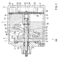
- a front housing 2 is coupled to the front end of a cylinder block 1 that defines one part of the outer wall of a compressor 100.
- a rear housing 5 that defines a suction chamber 3 and a discharge chamber 4 is coupled to the back end of the cylinder block 1 via a valve plate 6.
- a driving shaft 8 connected to a power source penetrates the driving chamber 7 within the front housing 2.
- the driving shaft 8 is rotatably supported by the cylinder block 1 and by the front housing 2.
- a rotating swash plate 12 is inclinably and slidably coupled to the driving shaft 8 via a rotor 9.
- the rotor 9 is coupled to the driving shaft 8.
- the driving shaft 8 is rotatably supported by bearings.
- a bearing 10 that supports one end portion of the driving shaft 8 is shown.
- the bearing 10 is disposed within the front housing 2.
- the rotor 9 is rotatably supported by a bearing 11 that is disposed within the front housing 2.
- the driving shaft 8 extends through a penetration hole 13 formed in the swash plate 12.
- the swash plate 12 may be inclinably and slidably coupled to the driving shaft 8.
- a hinge mechanism 26 is provided between the rotor 9 and the swash plate 12 to transmit the torque of the driving shaft 8 to the swash plate 12 that may rotate at various inclination angles.
- the penetration hole 13 preferably has a support point 13a.
- a spring 14 may be mounted on the driving shaft 8 between the rotor 9 and the swash plate 12 and a spring 15 may be mounted on the driving shaft 8 between the swash plate 12 and the cylinder block 1.
- the swash plate 12 may initially incline with respect to the plane perpendicular to the axis of the driving shaft 8 by way of the springs 14 and 15 when the compressor is not in operation.
- the spring 15 disposed within the cylinder block 1 is engaged by a snap ring 16.
- the cylinder block 1 preferably includes six cylinder bores 17. However, FIG. 1 only shows two pistons for purposes of illustration. Each piston 18 is reciprocally inserted into each cylinder bore 17. The piston 18 is coupled to the swash plate 12 via a shoe 19. The rotational movement of the swash plate 12 is converted into reciprocating movement of the pistons 18 via the shoe 19. As the result of the reciprocation of the piston 18, refrigerant in the suction chamber 3 is drawn into the cylinder bore 17 for compression from a suction port 20 via a suction valve 21. Then, the compressed refrigerant is discharged from a discharge port 22 to the discharge chamber 4 via a discharge valve 23.
- the suction valve 21, the discharge valve 23, and a valve retainer 24 are mounted on the valve plate 6 by utilizing a fastening screw 25.
- the driving chamber 7 preferably communicates with the discharge chamber 4 via a capacity control passage (not shown) that is opened and closed by a capacity control valve (not shown). The pressure state within the driving chamber 7 is controlled by the opening and closing the capacity control passage.
- the hinge mechanism 26 connects the swash plate 12 with the rotor 9 in order to transmit torque from the driving shaft 8 to the swash plate 12.
- the hinge mechanism 26 allows the swash plate 12 to change the inclination angle with respect to the plane perpendicular to the axis of the driving shaft 8.
- the hinge mechanism 26 includes a protrusion 27, cam members 28 and a pair of arms 29.
- the protrusion 27 is integrally coupled to the rotor 9, and a pair of the cam members 28 is respectively engaged with the side surfaces of the protrusion 27.
- Protrusion 27 preferably has a cutout construction, such as recess 27a.
- the arms 29 are integrally coupled to the swash plate 12 and the side of the swash plate 12 that faces the rotor 9.
- the arms 29 are disposed so as to sandwich the protrusion 27 in order to receive the torque that is transmitted from the protrusion 27 when the rotor 9 rotates together with the driving shaft 8.
- Head portions 29a of the arms 29 have a curved shape and contact cam surfaces 28a of the cam members 28, respectively.
- the cam members 29 include axial load accepting portions at the top end of the head portion 29a.
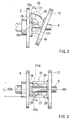
- the cam surface 28a has a slanting surface that tilts forward in order to maintain the upper dead point (top clearance) of the pistons 18 at a constant position regardless of variations in the inclination angle of the swash plate 12.
- piston 18 compresses the refrigerant within the cylinder bore 17 while another piston draws the refrigerant into another cylinder bore.
- the swash plate 12 receives a reaction force from the pistons 18 to push the swash plate 12 away from the piston 18.
- the area of the swash plate 12 where the swash plate 12 receives such reaction force is defined as a compression zone.
- the swash plate 12 receives a reaction force from the piston 18 to pull the swash plate 12 towards the piston 18.
- the area of the swash plate 12 where the swash plate 12 receives such reaction force is defined as a drawing zone.
- the hinge mechanism 26 is disposed between the rotor 9 and the swash plate 12 so as to straddle the boundary line 200-200 between the compression zone and the drawing zone.
- the swash plate 12 rotates via the hinge mechanism 26 and the piston 18 reciprocates within the cylinder bore 17.
- the refrigerant in the suction chamber 3 is drawn into the cylinder bore 17 via the suction port 20 and the suction valve 21.
- the compressed high pressure refrigerant is discharged from the discharge port 22 via the discharge valve 23 to the discharge chamber 4.
- the output discharge capacity of the compressor 100 can be changed by changing the length of the piston stroke as a result of changing the inclination angle of the swash plate 12.
- Changing the pressure within the driving chamber 7 can change the inclination angle of the swash plate 12. More specifically, when the pressure within the driving chamber 7 increases, backpressure acting on the piston 18 increases and the inclination angle of the swash plate 12 decreases with respect to the plane perpendicular to the driving shaft 8. As the inclination angle of the swash plate 12 decreases, the arm head portion 29a of the arm 29 moves towards the driving shaft 8 and the arm head portion 29a is pushed by the cam surface 28a. Thus, the swash plate 12 slides towards the cylinder block 1 (to the right in FIG. 2) and the swash plate 12 inclines to decrease its inclination angle. As the result, the piston stroke length decreases and the compressor output discharge capacity decreases.
- the backpressure acting on the pistons 18 decreases and the inclination angle of the swash plate 12 increases.
- the arm head portion 29a of the arm 29 moves away from the driving shaft 8 and slides up along the cam surface 28a.
- the swash plate 12 simultaneously slides toward the rotor 9.
- the maximum inclination angle of the swash plate 12 with respect to the maximum output discharge capacity is defined by the contact of an abutting surface 12a formed on the front surface of the swash plate 12 against a rear surface 9a of the rotor 9.
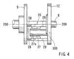
- the protrusion 27 includes a recessed structure 27a. Therefore, the weight of the protrusion 27 can be reduced while the horizontal width L (FIG. 3) that receives the reaction force of the piston 18 loaded onto the swash plate 12 can be substantially increased and the swash plate 12 can be supported in a stable manner.
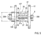
- the hinge mechanism 26 includes the projection 27 disposed on the rotor 9 and the arms 29 on the swash plate 12. The location of the projection 27 and the arms 29 are shifted in the circumferential direction of the swash plate 12 to correspond to the compression zone 300.
- the compression zone 300 is defined as the area where the swash plate 12 receives the reaction force of the piston 18 when the piston 18 compresses the refrigerant within the cylinder bore 17.
- the elements of the compressor other than the disposition of the hinge mechanism 26 are identical to the elements of the first embodiment. According to this embodiment, the compression zone of the swash plate 12 can be supported by the hinge mechanism 26 and therefore, twisting of the swash plate 12 can be prevented and smooth inclination of the swash plate 12 is enabled.
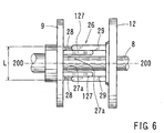
- the recessed structure 27a of the projection 27 may preferably shift in the rotating direction 301 of the swash plate 12.
- the left-side projection member 127 has a sufficient thickness at the torque transmitting area 129 to receive the rotating torque of the driving shaft 8.
- the center portion of the protrusion 27 may be completely removed such that the recessed structure 27a penetrates the projection 27 to reduce the weight of the projection 27 in the light of the centrifugal force caused by the rotation of the hinge mechanism 26.
- a plurality of protrusions 127, 128 corresponding to each of the arms 29 may be formed.
- an air conditioning system that includes the compressor 100 is shown in FIG. 7, wherein the refrigerant to operate the air conditioning system is compressed by the compressor.
- the invention is not limited to the above described embodiments.
- three arms 29 may be used, the central arm may be inserted into the recessed structure 27a of the protrusion 27, a cam member 28 may be disposed on the bottom of the recessed structure 27a, and the head portion of the arms 29 may contact with the cam surface 28a of the cam member 28.
- the arms 29 may be coupled to the rotor 9 while the. protrusion 27 and the cam member 28 may be coupled to the swash plate 12.
Landscapes
- Engineering & Computer Science (AREA)
- Mechanical Engineering (AREA)
- General Engineering & Computer Science (AREA)
- Compressors, Vaccum Pumps And Other Relevant Systems (AREA)
Applications Claiming Priority (2)
| Application Number | Priority Date | Filing Date | Title |
|---|---|---|---|
| JP2000116961 | 2000-04-18 | ||
| JP2000116961A JP2001304102A (ja) | 2000-04-18 | 2000-04-18 | 可変容量圧縮機 |
Publications (2)
| Publication Number | Publication Date |
|---|---|
| EP1148241A2 true EP1148241A2 (fr) | 2001-10-24 |
| EP1148241A3 EP1148241A3 (fr) | 2004-03-03 |
Family
ID=18628352
Family Applications (1)
| Application Number | Title | Priority Date | Filing Date |
|---|---|---|---|
| EP01109379A Withdrawn EP1148241A3 (fr) | 2000-04-18 | 2001-04-18 | Mécanisme de charnière pour un compresseur à capacité variable |
Country Status (3)
| Country | Link |
|---|---|
| US (1) | US6629823B2 (fr) |
| EP (1) | EP1148241A3 (fr) |
| JP (1) | JP2001304102A (fr) |
Cited By (3)
| Publication number | Priority date | Publication date | Assignee | Title |
|---|---|---|---|---|
| DE10324802A1 (de) * | 2003-06-02 | 2004-12-30 | Zexel Valeo Compressor Europe Gmbh | Axialkolbenverdichter, insbesondere CO2-Verdichter für Kraftfahrzeug-Klimaanlagen |
| DE10335159A1 (de) * | 2003-07-31 | 2005-02-17 | Zexel Valeo Compressor Europe Gmbh | Axialkolbenverdichter, insbesondere CO2-Verdichter für Kraftfahrzeug-Klimaanlagen |
| DE102019112245A1 (de) * | 2019-04-12 | 2020-10-15 | OET GmbH | Hubkolbenkompressor |
Families Citing this family (12)
| Publication number | Priority date | Publication date | Assignee | Title |
|---|---|---|---|---|
| JP2001200785A (ja) * | 2000-01-18 | 2001-07-27 | Toyota Autom Loom Works Ltd | 電動斜板圧縮機 |
| JP2003254231A (ja) * | 2001-12-25 | 2003-09-10 | Toyota Industries Corp | 容量可変型圧縮機 |
| US20050147503A1 (en) * | 2002-08-07 | 2005-07-07 | Hajime Kurita | Variable displacement compressor |
| US20050180860A1 (en) * | 2004-02-17 | 2005-08-18 | Dewispelaere Bradley J. | Compressor having swash plate assembly |
| JP4062265B2 (ja) | 2004-02-24 | 2008-03-19 | 株式会社豊田自動織機 | 可変容量圧縮機 |
| JP2006242120A (ja) * | 2005-03-04 | 2006-09-14 | Toyota Industries Corp | 容量可変型斜板式圧縮機 |
| US7455009B2 (en) * | 2006-06-09 | 2008-11-25 | Visteon Global Technologies, Inc. | Hinge for a variable displacement compressor |
| US7444921B2 (en) * | 2006-08-01 | 2008-11-04 | Visteon Global Technologies, Inc. | Swash ring compressor |
| CN101769244B (zh) * | 2008-12-29 | 2013-06-26 | 上海三电贝洱汽车空调有限公司 | 变排量压缩机的运动机构 |
| JP6094456B2 (ja) * | 2013-10-31 | 2017-03-15 | 株式会社豊田自動織機 | 容量可変型斜板式圧縮機 |
| JP6194830B2 (ja) * | 2014-03-24 | 2017-09-13 | 株式会社豊田自動織機 | 容量可変型斜板式圧縮機 |
| CN110454361A (zh) * | 2019-08-15 | 2019-11-15 | 台州动林汽车空调压缩机有限公司 | 汽车空调压缩机及其斜盘结构 |
Citations (1)
| Publication number | Priority date | Publication date | Assignee | Title |
|---|---|---|---|---|
| US6010312A (en) | 1996-07-31 | 2000-01-04 | Kabushiki Kaisha Toyoda Jidoshokki Seiksakusho | Control valve unit with independently operable valve mechanisms for variable displacement compressor |
Family Cites Families (7)
| Publication number | Priority date | Publication date | Assignee | Title |
|---|---|---|---|---|
| JP2626292B2 (ja) * | 1991-03-30 | 1997-07-02 | 株式会社豊田自動織機製作所 | 容量可変型斜板式圧縮機 |
| JP3422186B2 (ja) | 1995-11-24 | 2003-06-30 | 株式会社豊田自動織機 | 可変容量圧縮機 |
| JP3826473B2 (ja) * | 1997-02-28 | 2006-09-27 | 株式会社豊田自動織機 | 可変容量型圧縮機 |
| JPH11201032A (ja) * | 1998-01-13 | 1999-07-27 | Toyota Autom Loom Works Ltd | 可変容量型圧縮機 |
| JP2000073945A (ja) | 1998-06-15 | 2000-03-07 | Denso Corp | 斜板型圧縮機 |
| JP2000087848A (ja) * | 1998-09-08 | 2000-03-28 | Toyota Autom Loom Works Ltd | 可変容量型圧縮機 |
| US6139283A (en) * | 1998-11-10 | 2000-10-31 | Visteon Global Technologies, Inc. | Variable capacity swash plate type compressor |
-
2000
- 2000-04-18 JP JP2000116961A patent/JP2001304102A/ja active Pending
-
2001
- 2001-04-17 US US09/836,713 patent/US6629823B2/en not_active Expired - Fee Related
- 2001-04-18 EP EP01109379A patent/EP1148241A3/fr not_active Withdrawn
Patent Citations (1)
| Publication number | Priority date | Publication date | Assignee | Title |
|---|---|---|---|---|
| US6010312A (en) | 1996-07-31 | 2000-01-04 | Kabushiki Kaisha Toyoda Jidoshokki Seiksakusho | Control valve unit with independently operable valve mechanisms for variable displacement compressor |
Cited By (6)
| Publication number | Priority date | Publication date | Assignee | Title |
|---|---|---|---|---|
| DE10324802A1 (de) * | 2003-06-02 | 2004-12-30 | Zexel Valeo Compressor Europe Gmbh | Axialkolbenverdichter, insbesondere CO2-Verdichter für Kraftfahrzeug-Klimaanlagen |
| DE10335159A1 (de) * | 2003-07-31 | 2005-02-17 | Zexel Valeo Compressor Europe Gmbh | Axialkolbenverdichter, insbesondere CO2-Verdichter für Kraftfahrzeug-Klimaanlagen |
| DE102019112245A1 (de) * | 2019-04-12 | 2020-10-15 | OET GmbH | Hubkolbenkompressor |
| WO2020207936A1 (fr) | 2019-04-12 | 2020-10-15 | OET GmbH | Compresseur à pistons alternatifs |
| DE102019112237A1 (de) * | 2019-04-12 | 2020-10-15 | OET GmbH | Hubkolbenkompressor |
| WO2020207937A1 (fr) | 2019-04-12 | 2020-10-15 | OET GmbH | Compresseur à pistons alternatifs |
Also Published As
| Publication number | Publication date |
|---|---|
| EP1148241A3 (fr) | 2004-03-03 |
| US6629823B2 (en) | 2003-10-07 |
| US20010031205A1 (en) | 2001-10-18 |
| JP2001304102A (ja) | 2001-10-31 |
Similar Documents
| Publication | Publication Date | Title |
|---|---|---|
| US6629823B2 (en) | Compressors | |
| EP0780572B1 (fr) | Compresseur à plateau en biais | |
| EP0750115B1 (fr) | Compresseur à plateau en biais à capacité variable ayant un dispositif d'articulation amélioré pour supporter un plateau en biais avec inclinaison | |
| EP0698735A2 (fr) | Mécanisme de guidage pour piston alternatif de compresseur à piston | |
| US6402481B1 (en) | Variable capacity swash plate type compressor | |
| EP1394411B1 (fr) | Compresseur à déplacement variable du type à disque oblique | |
| US5931079A (en) | Variable capacity swash plate compressor | |
| US6010313A (en) | Single-headed piston type compressor | |
| EP0809024A1 (fr) | Piston alternatif de compresseur à piston | |
| US6524079B1 (en) | Alignment means for the swash plate of a variable-capacity swash-plate type compressor | |
| US7757597B2 (en) | Variable displacement swash plate type compressor with smooth inclined moving feature | |
| EP0881386B1 (fr) | Compresseur à plateau en biais | |
| EP0844392A2 (fr) | Compresseur à déplacement variable | |
| EP2096307A2 (fr) | Compresseur de type plaque inclinée | |
| EP1004769B1 (fr) | Compresseur à plateau en biais à capacité variable | |
| US6260469B1 (en) | Piston for use in a compressor | |
| EP0926339A2 (fr) | Revêtement d'un joint pivotable d'un plateau en biais | |
| JP2001295755A (ja) | 可変容量圧縮機のガイドピン及び可変容量圧縮機 | |
| US6705204B2 (en) | Swash plate-type | |
| EP1531266B1 (fr) | Compresseur à déplacement variable | |
| KR100519745B1 (ko) | 용량가변형 사판식 압축기 | |
| KR100532137B1 (ko) | 가변형 사판식 압축기 | |
| JP2000161207A (ja) | 可変容量斜板型圧縮機 | |
| JPH0756257B2 (ja) | 可変容量圧縮機 | |
| JPH0979130A (ja) | 斜板式コンプレッサ |
Legal Events
| Date | Code | Title | Description |
|---|---|---|---|
| PUAI | Public reference made under article 153(3) epc to a published international application that has entered the european phase |
Free format text: ORIGINAL CODE: 0009012 |
|
| 17P | Request for examination filed |
Effective date: 20010418 |
|
| AK | Designated contracting states |
Kind code of ref document: A2 Designated state(s): AT BE CH CY DE DK ES FI FR GB GR IE IT LI LU MC NL PT SE TR |
|
| AX | Request for extension of the european patent |
Free format text: AL;LT;LV;MK;RO;SI |
|
| RAP1 | Party data changed (applicant data changed or rights of an application transferred) |
Owner name: KABUSHIKI KAISHA TOYOTA JIDOSHOKKI |
|
| PUAL | Search report despatched |
Free format text: ORIGINAL CODE: 0009013 |
|
| AK | Designated contracting states |
Kind code of ref document: A3 Designated state(s): AT BE CH CY DE DK ES FI FR GB GR IE IT LI LU MC NL PT SE TR |
|
| AX | Request for extension of the european patent |
Extension state: AL LT LV MK RO SI |
|
| AKX | Designation fees paid |
Designated state(s): DE FR IT |
|
| STAA | Information on the status of an ep patent application or granted ep patent |
Free format text: STATUS: THE APPLICATION IS DEEMED TO BE WITHDRAWN |
|
| 18D | Application deemed to be withdrawn |
Effective date: 20060207 |