EP0926437A1 - Aménagement des brûleurs à gaz pour une surface de cuisson - Google Patents
Aménagement des brûleurs à gaz pour une surface de cuisson Download PDFInfo
- Publication number
- EP0926437A1 EP0926437A1 EP98124267A EP98124267A EP0926437A1 EP 0926437 A1 EP0926437 A1 EP 0926437A1 EP 98124267 A EP98124267 A EP 98124267A EP 98124267 A EP98124267 A EP 98124267A EP 0926437 A1 EP0926437 A1 EP 0926437A1
- Authority
- EP
- European Patent Office
- Prior art keywords
- gas
- burner
- valve
- arrangement according
- assigned
- Prior art date
- Legal status (The legal status is an assumption and is not a legal conclusion. Google has not performed a legal analysis and makes no representation as to the accuracy of the status listed.)
- Granted
Links
- 238000010411 cooking Methods 0.000 title description 2
- 239000000203 mixture Substances 0.000 claims abstract description 11
- 238000002485 combustion reaction Methods 0.000 claims description 2
- 230000007246 mechanism Effects 0.000 claims description 2
- 230000037431 insertion Effects 0.000 claims 1
- 238000003780 insertion Methods 0.000 claims 1
- 239000007789 gas Substances 0.000 description 80
- 238000010438 heat treatment Methods 0.000 description 10
- 230000000712 assembly Effects 0.000 description 2
- 238000000429 assembly Methods 0.000 description 2
- 230000015572 biosynthetic process Effects 0.000 description 1
- 238000010276 construction Methods 0.000 description 1
- 239000002737 fuel gas Substances 0.000 description 1
- 238000012544 monitoring process Methods 0.000 description 1
- 230000001105 regulatory effect Effects 0.000 description 1
Images


Classifications
-
- F—MECHANICAL ENGINEERING; LIGHTING; HEATING; WEAPONS; BLASTING
- F23—COMBUSTION APPARATUS; COMBUSTION PROCESSES
- F23D—BURNERS
- F23D14/00—Burners for combustion of a gas, e.g. of a gas stored under pressure as a liquid
- F23D14/02—Premix gas burners, i.e. in which gaseous fuel is mixed with combustion air upstream of the combustion zone
- F23D14/04—Premix gas burners, i.e. in which gaseous fuel is mixed with combustion air upstream of the combustion zone induction type, e.g. Bunsen burner
- F23D14/06—Premix gas burners, i.e. in which gaseous fuel is mixed with combustion air upstream of the combustion zone induction type, e.g. Bunsen burner with radial outlets at the burner head
- F23D14/065—Premix gas burners, i.e. in which gaseous fuel is mixed with combustion air upstream of the combustion zone induction type, e.g. Bunsen burner with radial outlets at the burner head with injector axis inclined to the burner head axis
-
- F—MECHANICAL ENGINEERING; LIGHTING; HEATING; WEAPONS; BLASTING
- F24—HEATING; RANGES; VENTILATING
- F24C—DOMESTIC STOVES OR RANGES ; DETAILS OF DOMESTIC STOVES OR RANGES, OF GENERAL APPLICATION
- F24C3/00—Stoves or ranges for gaseous fuels
- F24C3/08—Arrangement or mounting of burners
- F24C3/085—Arrangement or mounting of burners on ranges
-
- F—MECHANICAL ENGINEERING; LIGHTING; HEATING; WEAPONS; BLASTING
- F23—COMBUSTION APPARATUS; COMBUSTION PROCESSES
- F23D—BURNERS
- F23D2900/00—Special features of, or arrangements for burners using fluid fuels or solid fuels suspended in a carrier gas
- F23D2900/14—Special features of gas burners
- F23D2900/14062—Special features of gas burners for cooking ranges having multiple flame rings
Definitions
- the present invention relates to a gas burner arrangement for hotplates a multi-circuit gas burner with an internal burner with side gas-air mixture outlet openings and with low burning power and with one at a distance ring-shaped outer burner with gas-air mixture outlet openings arranged by the inner burner is equipped, as well as with a manually operated gas valve Passing through, dosing and shutting off the multi-circuit burner via separate Pipelines feedable burner gas.
- Such gas burner assemblies are usually used for heating, heating and preparing food for use, especially where there is high heating output be required.
- multi-circuit burners constructed in this way Heating outputs up to 5 kW and above can be realized.
- burners are particularly suitable such burners as wok burners.
- Multi-circuit gas burners are also used, to increase the control bandwidth by switching individual on and off To reach burner circuits whose heating output can also be changed.
- a gas burner arrangement designed according to these aspects is appropriate according to the invention, characterized in that the manually operable gas fitting three via an actuator that is adjustable in a plurality of adjustment positions and intermediate positions has gas duct branches that can be opened and closed by valves, two of which valve-actuated gas duct branches open for one each fixed gas throughput and another valve-loaded gas duct branch for an influenceable via the actuator and the associated valve variable gas throughput is designed so that a first of the gas channel branches with fixed assigned gas flow rate to the internal burner and starting from the Reset to zero if necessary after a preliminary stretch of the actuator setting whose full adjustment distance is opened by the associated valve and that the two other gas duct branches are assigned to the external burner and via a Part of the adjustment path that keeps the first gas duct branch open the assigned valves are activated.
- the gas burner arrangement according to the invention is in a preferred embodiment characterized in that the gas duct branches assigned to the external burner over an end section of the line that keeps the first gas channel branch open Adjustment distance of the actuator via the valves are activated, and that in the Starting position of this end section of the valve for the gas channel branching with the variable gas throughput fully opened and lockable in position analogous to the end position is.
- the gas burner arrangement according to the invention is thus characterized by a simple one Construction from that with high maximum burning power and relatively low minimum burning power can be operated in a user-friendly manner.
- the one with constant performance Internal burners can, for example, have a power between 300 W to 500 W. be designed and serves both as a burner for the lowest combustion power and preferred as a pilot burner, i.e. the ignition element is preferably in its vicinity to arrange which, depending on the form of use of the gas burner arrangement according to the invention by a piezo voltage generator or by an electronic one Voltage generator can be influenced.
- the use of a piezo voltage generator is preferred for portable gas burner units where an external Power supply is not secured.
- thermocouple possibly as a so-called flame monitoring element serves and acts on a closure element in the gas fitting, so that the gas flow to the burner is interrupted when the flame on the inner burner goes out is.
- the external burner can now, for example, have a maximum output of 5,000 W. be designed, this output of the external burner by throttling the gas supply can be regulated down to approx. 1,000 W.
- Both the gas supply for performance of the internal burner as well as the gas supply for the minimum output of the external burner are set as fixed values by gas duct branches in the gas valve dosed so that even at these relatively low values in the overall design of the High burner security is guaranteed.
- the maximum power of the burner is then achieved by an additional third channel branching in the valve, each can be variably set up to the maximum value at the operator's request can.
- the necessary Gas injector nozzle arrangement in the area of which the fuel gas mixes with the primary air will be arranged for the internal burner directly in the burner head while the corresponding one Gas injector nozzle arrangement for the external burner in the vicinity of the gas valve is arranged.
- the gas injector nozzle arrangement is provided up to the focal point completely sufficient to become a to lead good flame formation.
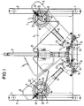
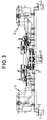
- gas burner assemblies 4 and associated gas fittings 5 attached for two hotplates.
- the completely identical trained gas burner arrangements 4 each have two burner circuits, namely one Inner burner 6 and an outer burner 7 arranged around it, and are with its feed channel for the gas-air mixture intended for the external burner 7 V-shaped in the direction of the gas fittings 5.
- a connection provided for a gas output 9 starting from the respective fitting 5, the gas injector nozzle arrangement arranged in the burner head of the gas burner arrangement 4 10 leads.
- the gas coming from the fitting 5 is passed through into the gas-air supply channel 8 a gas nozzle 13, which is part of the fitting body, taking primary air blown in.
- the intensive mixing of injected gas and suction Air to the external burner 7 is found in the gas-air supply duct 8 which is long enough instead of.
- an axially displaceable pipe socket 14 with an intake funnel 14 ' is assigned, over which the effective distance of the gas-air supply channel 8 to the nozzle 13 is changeable, whereby the air intake can also be changed.
- This pipe socket 14 can be actuated via an angle lever 15 mounted in the base plate by a rotary knob arrangement 16, the - not shown - operating button protrudes from the control panel - also not shown.
- the gas supply for the gas burner arrangements 4 of the two hotplates of the hob takes place centrally via a gas line 17, which is T-shaped between the two fittings 5 is connected to the two fittings 5.
- the two fittings 5 are constructed and arranged symmetrically to one another. They each contain three Gas channel branches, which have a rotary knob arrangement 18, which have a - not shown - open operating button protruding beyond the control panel and can be closed.
- One of the gas duct branches in the valve 5 is designed for constant gas throughput and 9 via the gas supply line Internal burner 6 assigned. After an initial rotary movement of the rotary toggle device 18 this gas channel branching is opened completely, for the whole further adjustment path of this rotary toggle device 18.
- an ignition electrode 20 is arranged in the vicinity of the inner burner 6.
- the ignition voltage for generating the ignition sparks is generated at the Embodiment according to FIGS. 1 and 5 with the aid of an ignition generator 21, which by one of the rotary toggle devices e.g. operable by axial pushing Contact 24 is activated or in the embodiment according to FIGS. 2 and 4 by the Actuation of a piezo element on which the rotary toggle device 18 acts by prepared by the pre-rotation or push-in movement of the Rotary knob device at the time of opening of said gas channel branch a striking movement is exerted on the piezo element 25.
- thermocouple 22 is arranged over which - as long as the flame on the inner burner 6 is present - a main valve 23 is kept open for the gas outlet.
- the nozzle 13 and thus the outer burner 7 are assigned to each of the gas burner arrangements 4. From the flame of the inner burner 6, the flame of the outer burner is ignited.
- One of the two assigned to the external burner 7 and to the gas nozzle 13 guided gas channel branches is variable with regard to the gas flow rate and can until the end of a predetermined angle of rotation of the rotary toggle device be completely closed.
- the second of the gas channel branches led to the gas nozzle 13 remains fully open during this time and is used for secure gas supply for the external burner 7 at minimum heating output.
- the design and arrangement of the gas burners for two hotplates is designed in this way and chosen that for simple and similar components for the two hotplate units can be used.
- the gas fittings 5 as well their associated adjustment mechanisms for the addition of air in the area of the nozzles 13 are mirror images and largely identical; the design of the Two-circuit gas burner arrangements 4 are completely identical. Nevertheless, it allows this Design that the actuating elements for the cooking area areas apart close together on the front panel and an actuation block form.
Landscapes
- Engineering & Computer Science (AREA)
- Chemical & Material Sciences (AREA)
- Combustion & Propulsion (AREA)
- Mechanical Engineering (AREA)
- General Engineering & Computer Science (AREA)
- Feeding And Controlling Fuel (AREA)
Applications Claiming Priority (2)
| Application Number | Priority Date | Filing Date | Title |
|---|---|---|---|
| DE19757733 | 1997-12-23 | ||
| DE19757733A DE19757733A1 (de) | 1997-12-23 | 1997-12-23 | Gasbrenneranordnung |
Publications (2)
| Publication Number | Publication Date |
|---|---|
| EP0926437A1 true EP0926437A1 (fr) | 1999-06-30 |
| EP0926437B1 EP0926437B1 (fr) | 2003-07-02 |
Family
ID=7853296
Family Applications (1)
| Application Number | Title | Priority Date | Filing Date |
|---|---|---|---|
| EP98124267A Expired - Lifetime EP0926437B1 (fr) | 1997-12-23 | 1998-12-18 | Aménagement des brûleurs à gaz pour une surface de cuisson |
Country Status (3)
| Country | Link |
|---|---|
| EP (1) | EP0926437B1 (fr) |
| DE (2) | DE19757733A1 (fr) |
| ES (1) | ES2202730T3 (fr) |
Cited By (3)
| Publication number | Priority date | Publication date | Assignee | Title |
|---|---|---|---|---|
| FR2804496A1 (fr) * | 2000-01-28 | 2001-08-03 | Sourdillon Sa | Bruleur a gaz a multiples couronnes de flammes |
| US6619279B1 (en) * | 2002-01-14 | 2003-09-16 | Tsung-Ming Liao | Broiler switch structure |
| US8307817B2 (en) | 2008-03-07 | 2012-11-13 | E.G.O. Elektro-Geraetebau Gmbh | Gas burner module for a gas cooktop, and gas cooktop |
Families Citing this family (2)
| Publication number | Priority date | Publication date | Assignee | Title |
|---|---|---|---|---|
| DE102010006276A1 (de) * | 2010-01-25 | 2011-07-28 | E.G.O. Elektro-Gerätebau GmbH, 75038 | Zweikreis-Brennersystem und Verfahren zum Betrieb eines solchen Zweikreis-Brennersystems |
| DE102012219039A1 (de) * | 2012-10-18 | 2014-04-24 | E.G.O. Elektro-Gerätebau GmbH | Verfahren zum Betrieb eines Gaskochgeräts und Gaskochgerät |
Citations (4)
| Publication number | Priority date | Publication date | Assignee | Title |
|---|---|---|---|---|
| US4518346A (en) * | 1983-04-29 | 1985-05-21 | Gaz De France | Gas fuel burner with incorporated ignition and safety devices |
| US5158067A (en) * | 1991-10-21 | 1992-10-27 | Dutro Company | Wok adapted portable food cooker |
| EP0552135A2 (fr) * | 1992-01-13 | 1993-07-21 | SMEG S.p.A. | Brûleur d'une cuisinière à gaz avec trois flammes concentriques |
| EP0732541A2 (fr) * | 1995-03-17 | 1996-09-18 | OVER ALL srl | Brûleur à gaz pour des tables de cuisson en vitrocéramique et pour le chauffage |
-
1997
- 1997-12-23 DE DE19757733A patent/DE19757733A1/de not_active Withdrawn
-
1998
- 1998-12-18 EP EP98124267A patent/EP0926437B1/fr not_active Expired - Lifetime
- 1998-12-18 ES ES98124267T patent/ES2202730T3/es not_active Expired - Lifetime
- 1998-12-18 DE DE59808898T patent/DE59808898D1/de not_active Expired - Lifetime
Patent Citations (4)
| Publication number | Priority date | Publication date | Assignee | Title |
|---|---|---|---|---|
| US4518346A (en) * | 1983-04-29 | 1985-05-21 | Gaz De France | Gas fuel burner with incorporated ignition and safety devices |
| US5158067A (en) * | 1991-10-21 | 1992-10-27 | Dutro Company | Wok adapted portable food cooker |
| EP0552135A2 (fr) * | 1992-01-13 | 1993-07-21 | SMEG S.p.A. | Brûleur d'une cuisinière à gaz avec trois flammes concentriques |
| EP0732541A2 (fr) * | 1995-03-17 | 1996-09-18 | OVER ALL srl | Brûleur à gaz pour des tables de cuisson en vitrocéramique et pour le chauffage |
Cited By (5)
| Publication number | Priority date | Publication date | Assignee | Title |
|---|---|---|---|---|
| FR2804496A1 (fr) * | 2000-01-28 | 2001-08-03 | Sourdillon Sa | Bruleur a gaz a multiples couronnes de flammes |
| EP1120603A3 (fr) * | 2000-01-28 | 2001-08-16 | Sourdillon | Brûleur à gaz à multiples couronnes de flammes |
| US6325619B2 (en) | 2000-01-28 | 2001-12-04 | Sourdillon | Gas burner with multiple gas rings |
| US6619279B1 (en) * | 2002-01-14 | 2003-09-16 | Tsung-Ming Liao | Broiler switch structure |
| US8307817B2 (en) | 2008-03-07 | 2012-11-13 | E.G.O. Elektro-Geraetebau Gmbh | Gas burner module for a gas cooktop, and gas cooktop |
Also Published As
| Publication number | Publication date |
|---|---|
| DE19757733A1 (de) | 1999-06-24 |
| EP0926437B1 (fr) | 2003-07-02 |
| ES2202730T3 (es) | 2004-04-01 |
| DE59808898D1 (de) | 2003-08-07 |
Similar Documents
| Publication | Publication Date | Title |
|---|---|---|
| DE69001128T2 (de) | Gaskochmulde. | |
| EP2014979A2 (fr) | Dispositif de fonctionnement pour un brûleur de surface haute performance et son procédé de fonctionnement | |
| DE3010078C2 (de) | Mit flüssigem Brennstoff betriebener Brenner für Heizvorrichtungen | |
| DE19746788C1 (de) | Gasregelarmatur | |
| EP0926446B1 (fr) | Aménagement des brûleurs à gaz pour une surface de cuisson | |
| EP0926437B1 (fr) | Aménagement des brûleurs à gaz pour une surface de cuisson | |
| DE69729755T2 (de) | Betätigungsvorrichtung für mehrventilgasbrenner | |
| DE2642401A1 (de) | Elektrischer schalter zur zuendung von gasen | |
| EP0283435B1 (fr) | Brûleur | |
| EP2413031B1 (fr) | Dispositif de combustion à prémélange | |
| EP0926438B1 (fr) | Aménagement des brûleurs à gaz pour une surface de cuisson | |
| EP3149406A2 (fr) | Soupape de régulation de gaz, table de cuisson et cuisinière à gaz | |
| EP0415049A2 (fr) | Arrangement de buse pour un brûleur à gaz | |
| DE3223108C2 (de) | Verdampfungsölbrenner | |
| EP0097315B1 (fr) | Dispositif de brûleur à fuel pour fourneaux roulants | |
| DE60212285T2 (de) | Absperreinrichtung des Gasstroms in einem Gasgerät | |
| EP0495358B1 (fr) | Dispositif de manoeuvre pour la régulation de puissance à deux étages d'un brûleur soufflant à gaz | |
| DE2453469A1 (de) | Verdampferoelbrenner | |
| DE102018103905B4 (de) | Zweikreis-Gaskochstelle und Verfahren zum Verhindern eines Düsenbrands bei einer Zweikreis-Gaskochstelle | |
| DE4237719C2 (de) | Atmosphärischer Gasbrenner | |
| DE202009018057U1 (de) | Ölbrenner und Regeleinrichtung hierzu | |
| EP2567154B1 (fr) | Dispositif de réglage de gaz | |
| DE2748743C2 (de) | Gasheizgerät | |
| WO2016075580A1 (fr) | Brûleur à gaz à admission d'air variable et plaque de cuisson à gaz | |
| DE3429686A1 (de) | Mit fluessigem brennstoff gespeister druckverdampfungsbrenner |
Legal Events
| Date | Code | Title | Description |
|---|---|---|---|
| PUAI | Public reference made under article 153(3) epc to a published international application that has entered the european phase |
Free format text: ORIGINAL CODE: 0009012 |
|
| AK | Designated contracting states |
Kind code of ref document: A1 Designated state(s): DE ES FR GB IT NL |
|
| AX | Request for extension of the european patent |
Free format text: AL;LT;LV;MK;RO;SI |
|
| 17P | Request for examination filed |
Effective date: 19991217 |
|
| AKX | Designation fees paid |
Free format text: DE ES FR GB IT NL |
|
| GRAH | Despatch of communication of intention to grant a patent |
Free format text: ORIGINAL CODE: EPIDOS IGRA |
|
| GRAH | Despatch of communication of intention to grant a patent |
Free format text: ORIGINAL CODE: EPIDOS IGRA |
|
| GRAA | (expected) grant |
Free format text: ORIGINAL CODE: 0009210 |
|
| AK | Designated contracting states |
Designated state(s): DE ES FR GB IT NL |
|
| REG | Reference to a national code |
Ref country code: GB Ref legal event code: FG4D Free format text: NOT ENGLISH |
|
| REF | Corresponds to: |
Ref document number: 59808898 Country of ref document: DE Date of ref document: 20030807 Kind code of ref document: P |
|
| GBT | Gb: translation of ep patent filed (gb section 77(6)(a)/1977) | ||
| RAP2 | Party data changed (patent owner data changed or rights of a patent transferred) |
Owner name: BSH BOSCH UND SIEMENS HAUSGERAETE GMBH |
|
| NLT2 | Nl: modifications (of names), taken from the european patent patent bulletin |
Owner name: BSH BOSCH UND SIEMENS HAUSGERAETE GMBH |
|
| REG | Reference to a national code |
Ref country code: ES Ref legal event code: FG2A Ref document number: 2202730 Country of ref document: ES Kind code of ref document: T3 |
|
| ET | Fr: translation filed | ||
| PLBE | No opposition filed within time limit |
Free format text: ORIGINAL CODE: 0009261 |
|
| STAA | Information on the status of an ep patent application or granted ep patent |
Free format text: STATUS: NO OPPOSITION FILED WITHIN TIME LIMIT |
|
| 26N | No opposition filed |
Effective date: 20040405 |
|
| REG | Reference to a national code |
Ref country code: DE Ref legal event code: R081 Ref document number: 59808898 Country of ref document: DE Owner name: BSH HAUSGERAETE GMBH, DE Free format text: FORMER OWNER: BSH BOSCH UND SIEMENS HAUSGERAETE GMBH, 81739 MUENCHEN, DE Effective date: 20150402 |
|
| REG | Reference to a national code |
Ref country code: ES Ref legal event code: PC2A Owner name: BSH HAUSGERATE GMBH Effective date: 20150527 |
|
| REG | Reference to a national code |
Ref country code: FR Ref legal event code: CD Owner name: BSH HAUSGERATE GMBH Effective date: 20151022 |
|
| REG | Reference to a national code |
Ref country code: FR Ref legal event code: PLFP Year of fee payment: 18 |
|
| PGFP | Annual fee paid to national office [announced via postgrant information from national office to epo] |
Ref country code: GB Payment date: 20151221 Year of fee payment: 18 |
|
| PGFP | Annual fee paid to national office [announced via postgrant information from national office to epo] |
Ref country code: ES Payment date: 20151218 Year of fee payment: 18 Ref country code: FR Payment date: 20151218 Year of fee payment: 18 Ref country code: NL Payment date: 20151221 Year of fee payment: 18 |
|
| PGFP | Annual fee paid to national office [announced via postgrant information from national office to epo] |
Ref country code: DE Payment date: 20151231 Year of fee payment: 18 |
|
| PGFP | Annual fee paid to national office [announced via postgrant information from national office to epo] |
Ref country code: IT Payment date: 20151222 Year of fee payment: 18 |
|
| REG | Reference to a national code |
Ref country code: DE Ref legal event code: R119 Ref document number: 59808898 Country of ref document: DE |
|
| REG | Reference to a national code |
Ref country code: NL Ref legal event code: MM Effective date: 20170101 |
|
| GBPC | Gb: european patent ceased through non-payment of renewal fee |
Effective date: 20161218 |
|
| PG25 | Lapsed in a contracting state [announced via postgrant information from national office to epo] |
Ref country code: NL Free format text: LAPSE BECAUSE OF NON-PAYMENT OF DUE FEES Effective date: 20170101 |
|
| REG | Reference to a national code |
Ref country code: FR Ref legal event code: ST Effective date: 20170831 |
|
| PG25 | Lapsed in a contracting state [announced via postgrant information from national office to epo] |
Ref country code: FR Free format text: LAPSE BECAUSE OF NON-PAYMENT OF DUE FEES Effective date: 20170102 Ref country code: IT Free format text: LAPSE BECAUSE OF NON-PAYMENT OF DUE FEES Effective date: 20161218 |
|
| PG25 | Lapsed in a contracting state [announced via postgrant information from national office to epo] |
Ref country code: DE Free format text: LAPSE BECAUSE OF NON-PAYMENT OF DUE FEES Effective date: 20170701 Ref country code: GB Free format text: LAPSE BECAUSE OF NON-PAYMENT OF DUE FEES Effective date: 20161218 |
|
| REG | Reference to a national code |
Ref country code: ES Ref legal event code: FD2A Effective date: 20180507 |
|
| PG25 | Lapsed in a contracting state [announced via postgrant information from national office to epo] |
Ref country code: ES Free format text: LAPSE BECAUSE OF FAILURE TO SUBMIT A TRANSLATION OF THE DESCRIPTION OR TO PAY THE FEE WITHIN THE PRESCRIBED TIME-LIMIT Effective date: 20030702 |
|
| PG25 | Lapsed in a contracting state [announced via postgrant information from national office to epo] |
Ref country code: ES Free format text: LAPSE BECAUSE OF FAILURE TO SUBMIT A TRANSLATION OF THE DESCRIPTION OR TO PAY THE FEE WITHIN THE PRESCRIBED TIME-LIMIT Effective date: 20161219 |
|
| RIC2 | Information provided on ipc code assigned after grant |
Ipc: F23D 14/58 20060101AFI19990331BHEP Ipc: F24C 3/08 20060101ALI19990331BHEP |