EP0926513A2 - Réseaux de lentilles barreaux pour système d'imagerie optique - Google Patents
Réseaux de lentilles barreaux pour système d'imagerie optique Download PDFInfo
- Publication number
- EP0926513A2 EP0926513A2 EP98124289A EP98124289A EP0926513A2 EP 0926513 A2 EP0926513 A2 EP 0926513A2 EP 98124289 A EP98124289 A EP 98124289A EP 98124289 A EP98124289 A EP 98124289A EP 0926513 A2 EP0926513 A2 EP 0926513A2
- Authority
- EP
- European Patent Office
- Prior art keywords
- refractive index
- rod lenses
- rod
- imaging system
- index distribution
- Prior art date
- Legal status (The legal status is an assumption and is not a legal conclusion. Google has not performed a legal analysis and makes no representation as to the accuracy of the status listed.)
- Withdrawn
Links
- 238000012634 optical imaging Methods 0.000 title claims abstract description 57
- 230000003287 optical effect Effects 0.000 claims abstract description 50
- 239000000758 substrate Substances 0.000 claims description 15
- 230000004304 visual acuity Effects 0.000 abstract description 15
- 230000004075 alteration Effects 0.000 description 10
- 239000006059 cover glass Substances 0.000 description 6
- 201000009310 astigmatism Diseases 0.000 description 4
- 238000003384 imaging method Methods 0.000 description 4
- 230000007423 decrease Effects 0.000 description 3
- 230000002093 peripheral effect Effects 0.000 description 3
- 238000003825 pressing Methods 0.000 description 3
- 230000005540 biological transmission Effects 0.000 description 2
- 150000001875 compounds Chemical class 0.000 description 2
- 239000011521 glass Substances 0.000 description 2
- 238000004519 manufacturing process Methods 0.000 description 2
- 239000000463 material Substances 0.000 description 2
- 238000005259 measurement Methods 0.000 description 2
- 229920003217 poly(methylsilsesquioxane) Polymers 0.000 description 2
- 239000000057 synthetic resin Substances 0.000 description 2
- 229920003002 synthetic resin Polymers 0.000 description 2
- 238000003491 array Methods 0.000 description 1
- 230000001419 dependent effect Effects 0.000 description 1
- 239000000203 mixture Substances 0.000 description 1
- 230000000630 rising effect Effects 0.000 description 1
Images












Classifications
-
- G—PHYSICS
- G02—OPTICS
- G02B—OPTICAL ELEMENTS, SYSTEMS OR APPARATUS
- G02B3/00—Simple or compound lenses
- G02B3/0087—Simple or compound lenses with index gradient
-
- G—PHYSICS
- G02—OPTICS
- G02B—OPTICAL ELEMENTS, SYSTEMS OR APPARATUS
- G02B13/00—Optical objectives specially designed for the purposes specified below
- G02B13/0095—Relay lenses or rod lenses
-
- G—PHYSICS
- G02—OPTICS
- G02B—OPTICAL ELEMENTS, SYSTEMS OR APPARATUS
- G02B3/00—Simple or compound lenses
- G02B3/0006—Arrays
- G02B3/0037—Arrays characterized by the distribution or form of lenses
- G02B3/005—Arrays characterized by the distribution or form of lenses arranged along a single direction only, e.g. lenticular sheets
-
- G—PHYSICS
- G02—OPTICS
- G02B—OPTICAL ELEMENTS, SYSTEMS OR APPARATUS
- G02B3/00—Simple or compound lenses
- G02B3/0006—Arrays
- G02B3/0037—Arrays characterized by the distribution or form of lenses
- G02B3/0056—Arrays characterized by the distribution or form of lenses arranged along two different directions in a plane, e.g. honeycomb arrangement of lenses
Definitions
- This invention relates to an optical imaging system used in an image transmission portion of, for example, a facsimile device or a copier. More particularly, the invention relates to an optical imaging system comprising a plurality of rod lenses arranged in an array.
- Optical imaging systems comprising a plurality of rod lenses with a refractive index distribution in a radial direction that are arranged in an array are widely used in the image transmission portion of, for example, facsimile devices or copiers.
- r is the radial distance from the optical axis of the rod lens
- n(r) is the refractive index at the radial distance r from the optical axis of the rod lenses
- n 0 is the refractive index at the optical axis of the rod lens (center refractive index)
- g, h 4 and h 6 are coefficients for the refractive index distribution.
- the resolving power demanded from such a rod lens array called for an MTF (modulation transfer function) of at least 60% when a pattern of 4 - 6 line-pairs/mm (ca. 200dpi - 300dpi) was imaged.
- MTF modulation transfer function
- the optimum refractive index distribution changes also with the brightness of the rod lenses. For example, in the case of bright rod lenses with a large aperture angle, the refractive index distribution coefficients for a small axial spherical aberration are very different from the refractive index distribution coefficients for a small image curvature. The best resolving power can be attained by striking a balance between the two.
- the refractive index distribution coefficients have to be determined separately in accordance with at least the numerical angle and the overlapping degree of each rod lens.
- the present invention has been developed with consideration of these facts.
- the purpose of the present invention is to provide an optical imaging system comprising a plurality of rod lenses arranged in an array, and having a refractive index distribution that is ideal for attaining a high resolving power.
- a first configuration of an optical imaging system for focusing light from a manuscript (i.e. object) plane onto an image plane comprises a rod lens array having a plurality of rod lenses with a refractive index distribution in a radial direction that are arranged in one row so that their optical axes are parallel.
- the refractive index distribution coefficients h 4 and h 6 are in ranges defined by c-d ⁇ h 4 ⁇ c+d ⁇ (h 4 -c) / d ⁇ 2 + [ ⁇ h 6 - (a ⁇ h 4 + b) ⁇ / e] 2 ⁇ 1 .
- an optical imaging system which comprises a plurality of rod lenses, arranged in an array, that have a suitable refractive index distribution for attaining a high resolving power of at least 12 line-pairs/mm (ca. 600dpi) if the outer diameter of the lenses is 0.6mm.
- a second configuration of an optical imaging system for focusing light from an object plane onto an image plane in accordance with the present invention comprises a rod lens array having a plurality of rod lenses with a refractive index distribution in a radial direction that are arranged in two rows so that their optical axes are parallel.
- the refractive index distribution coefficients h 4 and h 6 are in the ranges defined by c - d ⁇ h 4 ⁇ c + d and ⁇ (h 4 - c) / d ⁇ 2 + [ ⁇ h 6 - (a ⁇ h 4 + b) ⁇ / e] 2 ⁇ 1.
- an optical imaging system which comprises a plurality of rod lenses, arranged in an array, that have a suitable refractive index distribution for attaining a high resolving power of at least 12 line-pairs/mm (ca. 600dpi) if the outer diameter of the lenses is 0.6mm.
- the refractive distribution coefficients h 4 and h 6 are in ranges defined by c - d / 2 ⁇ h 4 ⁇ c + d / 2 ⁇ 2 (h 4 - c) / d ⁇ 2 + [2 ⁇ h 6 - (a ⁇ h 4 + b) ⁇ / e] 2 ⁇ 1.
- the refractive index n 0 at the optical axis of the rod lenses is in a range of 1.4 ⁇ n 0 ⁇ 1.8.
- the product g ⁇ r 0 of the refractive index distribution coefficient g and the radius r 0 of the portion of the rod lenses functioning as a lens is in a range of 0.04 ⁇ g ⁇ r 0 ⁇ 027 . If g ⁇ r 0 is smaller than 0.04, the image becomes too dark and the time for scanning etc. becomes long. If g ⁇ r 0 is larger than 0.27, the influence of the image curvature and the astigmatism becomes too large and the resolving power decreases.
- the radius r 0 of the portion of the rod lenses functioning as a lens is in a range of 0.05mm ⁇ r 0 ⁇ 0.60mm. According to this configuration, production and assembly of the rod lenses become easy, and the aberrations of the rod lens array can be kept small.
- r 0 / R is in the range 0.5 ⁇ r 0 / R ⁇ 1.0 , wherein r 0 is the radius of the portion of the rod lenses functioning as a lens and 2R is a distance between the optical axis of two neighboring rod lenses.
- a parallel plane transparent substrate is arranged so that the object plane is positioned at a front focal position of the rod lens array.
- the object plane can be set at the front focal position just by pressing the manuscript to the surface of the transparent substrate.
- the parallel plane substrate contacts the lens surfaces of the rod lens array. This can be easily realized by adjusting the thickness of the transparent substrate. According to this embodiment, the adjustment of the distance between the rod lens array and the front focal position can be simplified, which makes the assembly of the optical imaging system cheaper.
- a plurality of columnar rod lenses 1 with a refractive index distribution in the radial direction is arranged in one row in a rod lens array 2 for one-tone imaging with their optical axes 1a in parallel.
- This optical imaging system focuses light from an object plane 3 onto an image plane 4, the planes being arranged on the two sides of the rod lens array 2.
- r is a radial distance from an optical axis 1a of the rod lenses 1
- n(r) is the refractive index at the radial distance r from the optical axis 1a of the rod lens
- n 0 is the refractive index at the optical axis 1a of the rod lenses 1 (center refractive index)
- g, h 4 and h 6 are coefficients of the refractive index distribution.
- the radius r 0 of the effective rod lens portion that is the radius of the rod lens portion functioning as a lens, is in a range of 0.05mm ⁇ r 0 ⁇ 0.60mm.
- Lenses with a small r 0 can attain a high resolution more easily because the amount of image distortion due to the various aberrations of the rod lenses 1 increases proportionally with the size of the entire lens.
- rod lenses 1 with an r 0 smaller than 0.05mm are difficult to produce and to assemble.
- the radius r 0 of the effective rod lens portions in the rod lens array 2 is larger than 0.60mm, the aberration becomes too large.
- the realizable value n 0 for the refractive index at the optical axis 1a of the rod lenses 1 depends on the material for the rod lenses (glass or synthetic resin) and is in the range of 1.4 ⁇ n 0 ⁇ 1.8.
- the brightness of the rod lenses 1 depends on the dimensionless factor g ⁇ r 0 or from the aperture angle indicating the range over which the lenses can accept light.
- the dimensionless factor g ⁇ r 0 is in the range 0.04 ⁇ g ⁇ r 0 ⁇ 0.27 . If g ⁇ r 0 is smaller than 0.04, the image becomes too dark and the time for scanning etc. becomes long. If g ⁇ r 0 is larger than 0.27, the influence of the image curvature and the astigmatism becomes too large and the resolving power decreases.
- a compound image is formed by the rod lenses 1 on the image plane 4, as is shown in Fig. 5, so that it is convenient to introduce a dimensionless factor describing the amount of overlap, that is, the so-called "overlapping degree".
- the overlapping degree m of the rod lens array 2 is in the range 1.0 ⁇ m ⁇ 5.0. If the overlapping degree m is larger than 5.0, the image becomes too dark and the time for scanning etc. becomes long. If the overlapping degree m is smaller than 1.0, periodical irregularities appear in the brightness of the image plane 4.
- the distance 2R between the optical axes of neighboring rod lenses 1 with 2r 0 (diameter of the effective lens portion of the rod lenses 1), since then the largest amount of light can be focused onto the image.
- the refractive index distribution at the peripheral portion of the rod lenses 1 can differ considerably from the designed value, this portion can often not be used for the lens.
- the lenses comprise a light-absorbing layer to prevent stray light due to total reflection at the lens side surface.
- the rod lenses 1 are arranged with a certain distance between each other. Considering the above circumstances, the ratio r 0 / R is set in the range of 0.5 ⁇ r 0 / R ⁇ 1.0 .
- the inventors took the standard for "high resolution” to mean “a value of at least 50% for the MTF of a 24 line-pairs/mm pattern on a center line of a rod lens array 2 comprising a plurality of rod lenses 1, which have an effective lens portion radius r 0 of 0.15mm and are arranged in one row so that their optical axes 1a are parallel", and determined the refractive index distribution coefficients h 4 and h 6 that fulfill this standard.
- a rod lens array 2 with the above configuration was designed. Ray tracing was performed taking the perpendicular projection of point A as indicated in Fig. 6 onto the object plane for the light source. The MTF values of a 24 line-pairs/mm pattern were calculated for the X direction and for the Y direction, and the smaller value was taken as the MTF value for the rod lens array 2. The optical design software "Oslo Six" by Sinclair Optics (US) was used for the ray tracing. Then, for a rod lens array 2 with parameters as shown in Table 1, a range of the refractive index distribution coefficients h 4 and h 6 for which the MTF value of a 24 line-pairs/mm pattern is at least 50% was determined.
- This range is called “good image range” of the refractive index distribution coefficients h 4 and h 6 below.
- the wavelength ⁇ of the light for the calculation of the MTF value was taken to be 587.6nm.
- the upper limit of the resolving power due to diffraction is sufficiently larger than necessary for this good image range. Consequently in the wavelength region where the rod lens array is normally used (about 300 - 2000nm), the same good image range can be applied regardless of the wavelength.
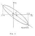
- the good image range can be drawn as a narrow ellipse in a Cartesian coordinate system having h 4 as the X-axis and h 6 as the Y-axis, as shown in Fig. 7.
- This good image range can be expressed by c-d ⁇ h 4 ⁇ c+d ⁇ (h 4 - c) / d ⁇ 2 + [ ⁇ h 6 - (a ⁇ h 4 + b) ⁇ / e] 2 ⁇ 1
- a is the slope of the central axis
- b is the intercept of the central axis with the h 6 -axis
- c is the h 4 -coordinate of the center of the central axis
- d is the half width of the range spanned by the ellipse in the h 4 -direction
- e is the half width of the ellipse in the h 6 -direction at its central h 4 -value.
- the constant c has the constant value 1.
- the radius r 0 of the effective lens portion of the rod lenses 1 takes a value other than 15mm, so that the amount of image distortion resulting from all aberrations of the rod lenses 1 increases proportionally to r 0 , so that the good image range for the refractive index distribution coefficients h 4 and h 6 defined by Eqs. 55, 56, and 63 to 67 generally describes the following ranges:
- a transparent substrate 5 with a parallel plane surface (cover glass) is arranged in a manner that the object plane 3 is located at the front focal position of the rod lens array 2, as shown in Fig. 16 (a).
- the object plane 3 can be set at the front focal position just by pressing the manuscript to the surface of the transparent substrate 5.
- the parallel plane transparent substrate (cover glass) 5 contacts the lens surface of the rod lens array 2, as shown in Fig. 16 (b). This can be easily realized by adjusting the thickness of the transparent substrate (cover glass) 5. According to this embodiment, the adjustment of the distance between the rod lens array 2 and the front focal position can be simplified, which makes the assembly of the optical imaging system cheaper.
- the good image range is defined by Eqs. 55 and 56, but an even better image range can be achieved by defining it with c - d / 2 ⁇ h 4 ⁇ c + d / 2 ⁇ 2 (h 4 - c) / d ⁇ 2 + [2 ⁇ h 6 - (a ⁇ h 4 + b) ⁇ / e] 2 ⁇ 1.
- the refractive index distribution of the rod lenses 1 is expressed by Eq. 51.
- the refractive index distribution can be expressed by the general Eq. 70, and f(r) satisfies h 4A ⁇ (g ⁇ r) 4 + h 6A ⁇ (g ⁇ r) 6 ⁇ f(r) ⁇ h 4B ⁇ (g ⁇ r) 4 + h 6B ⁇ (g ⁇ r) 6 for r in a range of 0 ⁇ r ⁇ r 0 for two groups of refractive index distribution coefficients (n 0 , g, h 4A , h 6A and (n 0 , g, h 4B , h 6B ) that are in the ranges defined by Eqs. 55, 56, and 63 to 67, as shown in Fig. 17, then a "good image range" can be attained for the refractive index distribution.
- a plurality of columnar rod lenses 1 with a refractive index distribution in the radial direction are arranged in two rows in a rod lens array 2 for one-to-one imaging with their optical axes 1a in parallel.
- This optical imaging system focuses light from an object plane 3 onto an image plane 4, the planes being arranged on the two sides of the rod lens array 2.
- r is a radial distance from an optical axis 1a of the rod lenses 1
- n(r) is the refractive index at the radial distance r from the optical axis 1a of the rod lens
- n 0 is the refractive index at the optical axis 1a of the rod lenses 1 (center refractive index)
- g, h 4 and h 6 are coefficients of the refractive index distribution.
- the radius r 0 of the effective rod lens portion that is the radius of the rod lens 1 functioning as a lens is in a range of 0.05mm ⁇ r 0 ⁇ 0.60mm.
- Lenses with a small r 0 can attain a high resolution more easily, because the amount of image distortion due to the various aberrations of the rod lenses 1 increases proportionally with the size of the entire lens.
- rod lenses 1 with an r 0 smaller than 0.05mm are difficult to produce and to assemble.
- the radius r 0 of the effective rod lens portions in the rod lens array 2 is larger than 0.60mm, the aberration becomes too large.
- the realizable value n 0 for the refractive index at the optical axis 1a of the rod lenses 1 depends on the material for the rod lenses (glass or synthetic resin) and is in the range of 1.4 ⁇ n 0 ⁇ 1.8.
- the brightness of the rod lenses 1 depends on the dimensionless factor g ⁇ r 0 or from the aperture angle indicating the range over which the lenses can accept light.
- the dimensionless factor g ⁇ r 0 is in the range 0.04 ⁇ g ⁇ r 0 ⁇ 0.27. If g ⁇ r 0 is smaller than 0.04, the image becomes too dark and the time for scanning etc. becomes long. If g ⁇ r 0 is larger than 0.27, the influence of the image curvature and the astigmatism becomes too large and the resolving power decreases.
- a compound image is formed by the rod lenses 1 on the image plane 4, as is shown in Fig. 5, so that it is convenient to introduce a dimensionless factor describing the amount of overlap, that is, the so-called "overlapping degree".
- the overlapping degree m of the rod lens array 2 is in the range 1.0 ⁇ m ⁇ 5.0. If the overlapping degree m is larger than 5.0, the image becomes too dark and the time for scanning etc. becomes long. If the overlapping degree m is smaller than 1.0, periodical irregularities appear in the brightness of the image plane 4.
- the distance 2R between the optical axes of neighboring rod lenses 1 with 2r 0 (diameter of the effective lens portion of the rod lenses 1), since then the largest amount of light can be focused on the image.
- the refractive index distribution at the peripheral portion of the rod lenses 1 can differ considerably from the designed value, this portion can often not be used for the lens.
- the lenses comprise a light-absorbing layer to prevent stray light due to total reflection at the lens side surface.
- the rod lenses 1 are arranged with a certain distance between each other. Considering the above circumstances, the ratio r 0 / R is set in the range of 0.5 ⁇ r 0 / R ⁇ 1.0 .
- the inventors took the standard for "high resolution” to mean “a value of at least 50% for the MTF of a 24 line-pairs/mm pattern on a center line of a rod lens array 2 comprising a plurality of rod lenses 1, which have an effective lens portion radius r 0 of 0.15mm and are arranged in two rows so that their optical axes 1a are parallel", and determined the refractive index distribution coefficients h 4 and h 6 that fulfill this standard.
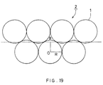
- a rod lens array 2 with the above configuration was designed. Ray tracing was performed taking the perpendicular projection of a point B as indicated in Fig. 19 onto the object plane for the light source. The MTF values of a 24 line-pairs/mm pattern were calculated for the X direction and for the Y direction, and the smaller value was taken as the MTF value for the rod lens array 2. The optical design software "Oslo Six" by Sinclair Optics (US) was used for the ray tracing. Then, for a rod lens array 2 with parameters as shown in Table 1, a range of the refractive index distribution coefficients h 4 and h 6 for which the MTF value of a 24 line-pairs/mm pattern is at least 50% was determined. This range is called "good image range" of the refractive index distribution coefficients h 4 and h 6 below.
- the good image range can be drawn as a narrow ellipse in a Cartesian coordinate system having h 4 as the X-axis and h 6 as the Y-axis, as shown in Fig. 7.
- This good image range can be expressed by c - d ⁇ h 4 ⁇ c + d ⁇ (h 4 - c) / d ⁇ 2 + [ ⁇ h 6 - (a ⁇ h 4 + b) ⁇ / e] 2 ⁇ 1
- a is the slope of the central axis
- b is the intercept of the central axis with the h 6 -axis
- c is the h 4 -coordinate of the center of the central axis
- d is the half width of the range spanned by the ellipse in the h 4 -direction
- e is the half width of the ellipse in the h 6 -direction at its central h 4 -value.
- the constant c has the constant value 1.
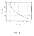
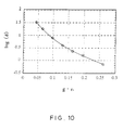
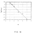
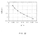
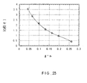
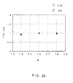
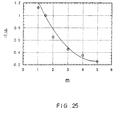
- log means the common logarithm with a base of 10.
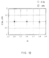
- the normalized values of d and e become smaller when m becomes large, so that the good image range shrinks.
- the good image range for the refractive index distribution coefficients h 4 and h 6 defined by Eqs. 76, 77, and 84 to 88 generally describes the following ranges:
- a transparent substrate (cover glass) 5 with a parallel plane surface is arranged in a manner that the object plane 3 is located at the front focal position of the rod lens array 2, as shown in Fig. 16 (a).
- the object plane 3 can be set at the front focal position just by pressing the manuscript to the surface of the transparent substrate 5.
- the parallel plane transparent substrate (cover glass) 5 contacts the lens surface of the rod lens array 2, as shown in Fig. 16 (b). This can be easily realized by adjusting the thickness of the transparent substrate (cover glass) 5. According to this embodiment, the adjustment of the distance between the rod lens array 2 and the front focal position can be simplified, which makes the assembly of the optical imaging system cheaper.
- the good image range is defined by Eqs. 76 and 77, but an even better image range can be achieved by defining it with c - d / 2 ⁇ h 4 ⁇ c + d / 2 ⁇ 2 (h 4 - c) / d ⁇ 2 + [2 ⁇ h 6 - (a ⁇ h 4 + b) ⁇ / e] 2 ⁇ 1.
- the refractive index distribution of the rod lenses 1 is expressed by Eq. 72.
- the refractive index distribution can be expressed by the general Eq. 91, and f(r) satisfies h 4A ⁇ (g ⁇ r) 4 + h 6A ⁇ (g ⁇ r) 6 ⁇ f(r) ⁇ h 4B ⁇ (g ⁇ r) 4 + h 6B ⁇ (g ⁇ r) 6 in a range of 0 ⁇ r ⁇ r 0 for two groups of refractive index distribution coefficients (n 0 , g, h 4A , h 6A ) and (n 0 , g, h 4B , h 6B ) that are in the ranges defined by Eqs. 76, 77, and 84 to 88, as shown in Fig. 17, then a "good image range can be attained for the refractive index distribution.
Landscapes
- Physics & Mathematics (AREA)
- General Physics & Mathematics (AREA)
- Optics & Photonics (AREA)
- Lenses (AREA)
- Facsimile Heads (AREA)
Applications Claiming Priority (4)
| Application Number | Priority Date | Filing Date | Title |
|---|---|---|---|
| JP35507997 | 1997-12-24 | ||
| JP35507997A JP4191275B2 (ja) | 1997-12-24 | 1997-12-24 | 結像光学装置及びその製造方法 |
| JP03070698A JP3337413B2 (ja) | 1998-02-13 | 1998-02-13 | 結像光学装置 |
| JP3070698 | 1998-02-13 |
Publications (2)
| Publication Number | Publication Date |
|---|---|
| EP0926513A2 true EP0926513A2 (fr) | 1999-06-30 |
| EP0926513A3 EP0926513A3 (fr) | 1999-10-06 |
Family
ID=26369107
Family Applications (1)
| Application Number | Title | Priority Date | Filing Date |
|---|---|---|---|
| EP98124289A Withdrawn EP0926513A3 (fr) | 1997-12-24 | 1998-12-21 | Réseaux de lentilles barreaux pour système d'imagerie optique |
Country Status (3)
| Country | Link |
|---|---|
| US (1) | US6031668A (fr) |
| EP (1) | EP0926513A3 (fr) |
| TW (1) | TW405046B (fr) |
Cited By (6)
| Publication number | Priority date | Publication date | Assignee | Title |
|---|---|---|---|---|
| WO2001031368A1 (fr) * | 1999-10-27 | 2001-05-03 | Mitsubishi Rayon Co., Ltd. | Mosaique de lentilles, detecteur d'image, processeur d'informations et systeme de traitement d'informations comprenant le detecteur d'image |
| EP1231486A1 (fr) * | 2001-02-07 | 2002-08-14 | Nippon Sheet Glass Co., Ltd. | Réseaux de lentilles barreaux pour système d'imagerie optique |
| EP1191358A3 (fr) * | 2000-09-22 | 2003-06-04 | Nippon Sheet Glass Co., Ltd. | Matrice de lentilles barreaux pour balayage linéaire |
| EP1291186A3 (fr) * | 2001-09-06 | 2003-06-04 | Nippon Sheet Glass Co.,Ltd. | Tête d'enregistrement optique, appareil de formation d'images l'utilisant et méthode d'inspection de cet appareil |
| EP1111902A3 (fr) * | 1999-12-20 | 2003-12-03 | Nippon Sheet Glass Co., Ltd. | Système d'imagerie optique |
| US10837619B2 (en) | 2018-03-20 | 2020-11-17 | Ledengin, Inc. | Optical system for multi-emitter LED-based lighting devices |
Families Citing this family (7)
| Publication number | Priority date | Publication date | Assignee | Title |
|---|---|---|---|---|
| US6496214B1 (en) * | 1999-02-19 | 2002-12-17 | Ricoh Technology Research Inc. | Image forming elements array, and optical printing head and image forming apparatus using the array |
| AU1307401A (en) * | 1999-11-10 | 2001-06-06 | Hamamatsu Photonics K.K. | Optical lens and optical system |
| JP2001296406A (ja) * | 2000-04-11 | 2001-10-26 | Nippon Sheet Glass Co Ltd | 結像光学素子 |
| TW499571B (en) * | 2000-09-29 | 2002-08-21 | Nippon Sheet Glass Co Ltd | Rod lens array and a process for producing the same |
| JP2003121608A (ja) * | 2001-10-10 | 2003-04-23 | Nippon Sheet Glass Co Ltd | 等倍結像用レンズアレイ、同アレイを用いた画像読取り装置および同装置を用いた携帯電子機器 |
| JP4864509B2 (ja) * | 2006-03-31 | 2012-02-01 | 株式会社沖データ | レンズアレイ、露光装置、及び画像形成装置 |
| JP2017128045A (ja) * | 2016-01-20 | 2017-07-27 | 株式会社沖データ | 露光装置、画像形成ユニットおよび画像形成装置 |
Family Cites Families (5)
| Publication number | Priority date | Publication date | Assignee | Title |
|---|---|---|---|---|
| US4349248A (en) * | 1980-04-23 | 1982-09-14 | Xerox Corporation | Gradient index lens array with improved exposure uniformity |
| JP2684227B2 (ja) * | 1989-04-19 | 1997-12-03 | 三菱電機株式会社 | イメージセンサ |
| JP2815130B2 (ja) * | 1992-11-04 | 1998-10-27 | キヤノン株式会社 | レンズアレイ及びそれを用いた密着型イメージセンサー |
| JPH1114803A (ja) * | 1997-06-24 | 1999-01-22 | Nippon Sheet Glass Co Ltd | ロッドレンズアレイ及びそれを用いた等倍結像光学装置 |
| JP4132145B2 (ja) * | 1997-08-18 | 2008-08-13 | 日本板硝子株式会社 | 等倍結像光学装置 |
-
1998
- 1998-12-15 US US09/212,076 patent/US6031668A/en not_active Expired - Lifetime
- 1998-12-17 TW TW087121028A patent/TW405046B/zh not_active IP Right Cessation
- 1998-12-21 EP EP98124289A patent/EP0926513A3/fr not_active Withdrawn
Cited By (10)
| Publication number | Priority date | Publication date | Assignee | Title |
|---|---|---|---|---|
| WO2001031368A1 (fr) * | 1999-10-27 | 2001-05-03 | Mitsubishi Rayon Co., Ltd. | Mosaique de lentilles, detecteur d'image, processeur d'informations et systeme de traitement d'informations comprenant le detecteur d'image |
| US6654173B1 (en) | 1999-10-27 | 2003-11-25 | Mitsubishi Rayon Co., Ltd. | Lens array, image sensor, information processor and information processing system comprising the image sensor |
| EP1111902A3 (fr) * | 1999-12-20 | 2003-12-03 | Nippon Sheet Glass Co., Ltd. | Système d'imagerie optique |
| EP1191358A3 (fr) * | 2000-09-22 | 2003-06-04 | Nippon Sheet Glass Co., Ltd. | Matrice de lentilles barreaux pour balayage linéaire |
| EP1231486A1 (fr) * | 2001-02-07 | 2002-08-14 | Nippon Sheet Glass Co., Ltd. | Réseaux de lentilles barreaux pour système d'imagerie optique |
| US7012721B2 (en) | 2001-02-07 | 2006-03-14 | Nippon Sheet Glass Company Limited | Optical imaging system with rod lens array |
| EP1291186A3 (fr) * | 2001-09-06 | 2003-06-04 | Nippon Sheet Glass Co.,Ltd. | Tête d'enregistrement optique, appareil de formation d'images l'utilisant et méthode d'inspection de cet appareil |
| US6891558B2 (en) | 2001-09-06 | 2005-05-10 | Nippon Sheet Glass Co., Ltd. | Optical write-in head, image forming apparatus using the same, and method for inspecting the apparatus |
| US7071963B2 (en) | 2001-09-06 | 2006-07-04 | Nippon Sheet Glass Co., Ltd. | Optical write-in head, image forming apparatus using the same, and method for inspecting the apparatus |
| US10837619B2 (en) | 2018-03-20 | 2020-11-17 | Ledengin, Inc. | Optical system for multi-emitter LED-based lighting devices |
Also Published As
| Publication number | Publication date |
|---|---|
| TW405046B (en) | 2000-09-11 |
| EP0926513A3 (fr) | 1999-10-06 |
| US6031668A (en) | 2000-02-29 |
Similar Documents
| Publication | Publication Date | Title |
|---|---|---|
| US6366408B1 (en) | Optical imaging system | |
| US6781729B2 (en) | Optical scanning system with unvarying image surface under environmental temperature change | |
| EP0872754B1 (fr) | Appareil de balayage optique avec lentille diffractive pour compenser des variations de focalisation dépendant de la température | |
| US6791729B2 (en) | Adjusting imaging position of optical beam spot in main and sub-scanning directions by individually and/or collectively adjusting position(s) of temperature-compensating lens(es) | |
| JP3330248B2 (ja) | 光走査装置、画像形成装置及び画像読み取り装置 | |
| EP0926513A2 (fr) | Réseaux de lentilles barreaux pour système d'imagerie optique | |
| US8699077B2 (en) | Scanning optical apparatus and image forming apparatus using the same | |
| KR100676811B1 (ko) | 광학소자와 그것을 가지는 주사광학계 및 화상형성장치 | |
| EP0898181A2 (fr) | Réseaux de lentilles bareaux et appareillage d'imagerie en grandeur nature utilisant de tels réseaux | |
| EP1111902A2 (fr) | Système d'imagerie optique | |
| EP0786814A1 (fr) | Matrice d'éléments photodétecteurs avec compensation des aberrations optiques et des non-uniformités de l'illumination | |
| US6992807B2 (en) | Optical scanning apparatus and image forming apparatus using the same | |
| US6825870B2 (en) | Scanning optical apparatus with reduced wave aberration | |
| US20070285755A1 (en) | Scanning optical system, image formation apparatus including the scanning optical system, and imaging optical system used in the scanning optical system | |
| JP3337413B2 (ja) | 結像光学装置 | |
| JP2003107382A (ja) | 走査光学系 | |
| EP1191358A2 (fr) | Matrice de lentilles barreaux pour balayage linéaire | |
| EP0694802B1 (fr) | Dispositif de balayage optique | |
| US4586782A (en) | Laser beam optical system with inclined cylindrical lens | |
| US20020050562A1 (en) | Light scanner and image forming apparatus using the same | |
| EP1231486A1 (fr) | Réseaux de lentilles barreaux pour système d'imagerie optique | |
| US7087892B2 (en) | Light scanner and image forming apparatus using the same | |
| JP4191275B2 (ja) | 結像光学装置及びその製造方法 | |
| JP2004004154A (ja) | 走査光学系および光走査装置および画像形成装置 | |
| US20050168787A1 (en) | Scanning optical system |
Legal Events
| Date | Code | Title | Description |
|---|---|---|---|
| PUAI | Public reference made under article 153(3) epc to a published international application that has entered the european phase |
Free format text: ORIGINAL CODE: 0009012 |
|
| AK | Designated contracting states |
Kind code of ref document: A2 Designated state(s): DE FR GB |
|
| AX | Request for extension of the european patent |
Free format text: AL;LT;LV;MK;RO;SI |
|
| PUAL | Search report despatched |
Free format text: ORIGINAL CODE: 0009013 |
|
| AK | Designated contracting states |
Kind code of ref document: A3 Designated state(s): AT BE CH CY DE DK ES FI FR GB GR IE IT LI LU MC NL PT SE |
|
| AX | Request for extension of the european patent |
Free format text: AL;LT;LV;MK;RO;SI |
|
| RIC1 | Information provided on ipc code assigned before grant |
Free format text: 6G 02B 3/00 A, 6H 04N 1/031 B |
|
| 17P | Request for examination filed |
Effective date: 19991020 |
|
| AKX | Designation fees paid |
Free format text: DE FR GB |
|
| 17Q | First examination report despatched |
Effective date: 20030606 |
|
| GRAP | Despatch of communication of intention to grant a patent |
Free format text: ORIGINAL CODE: EPIDOSNIGR1 |
|
| STAA | Information on the status of an ep patent application or granted ep patent |
Free format text: STATUS: THE APPLICATION IS DEEMED TO BE WITHDRAWN |
|
| 18D | Application deemed to be withdrawn |
Effective date: 20040702 |