EP0926519B1 - Coupleur à fibre optique, procédé pour sa fabrication et amplificateur optique utilisant celui-ci - Google Patents
Coupleur à fibre optique, procédé pour sa fabrication et amplificateur optique utilisant celui-ci Download PDFInfo
- Publication number
- EP0926519B1 EP0926519B1 EP98124455A EP98124455A EP0926519B1 EP 0926519 B1 EP0926519 B1 EP 0926519B1 EP 98124455 A EP98124455 A EP 98124455A EP 98124455 A EP98124455 A EP 98124455A EP 0926519 B1 EP0926519 B1 EP 0926519B1
- Authority
- EP
- European Patent Office
- Prior art keywords
- optical
- fiber
- rare earth
- optical fiber
- doped
- Prior art date
- Legal status (The legal status is an assumption and is not a legal conclusion. Google has not performed a legal analysis and makes no representation as to the accuracy of the status listed.)
- Expired - Lifetime
Links
Images


Classifications
-
- G—PHYSICS
- G02—OPTICS
- G02B—OPTICAL ELEMENTS, SYSTEMS OR APPARATUS
- G02B6/00—Light guides; Structural details of arrangements comprising light guides and other optical elements, e.g. couplings
- G02B6/24—Coupling light guides
- G02B6/26—Optical coupling means
- G02B6/28—Optical coupling means having data bus means, i.e. plural waveguides interconnected and providing an inherently bidirectional system by mixing and splitting signals
- G02B6/2804—Optical coupling means having data bus means, i.e. plural waveguides interconnected and providing an inherently bidirectional system by mixing and splitting signals forming multipart couplers without wavelength selective elements, e.g. "T" couplers, star couplers
- G02B6/2821—Optical coupling means having data bus means, i.e. plural waveguides interconnected and providing an inherently bidirectional system by mixing and splitting signals forming multipart couplers without wavelength selective elements, e.g. "T" couplers, star couplers using lateral coupling between contiguous fibres to split or combine optical signals
- G02B6/2835—Optical coupling means having data bus means, i.e. plural waveguides interconnected and providing an inherently bidirectional system by mixing and splitting signals forming multipart couplers without wavelength selective elements, e.g. "T" couplers, star couplers using lateral coupling between contiguous fibres to split or combine optical signals formed or shaped by thermal treatment, e.g. couplers
-
- H—ELECTRICITY
- H01—ELECTRIC ELEMENTS
- H01S—DEVICES USING THE PROCESS OF LIGHT AMPLIFICATION BY STIMULATED EMISSION OF RADIATION [LASER] TO AMPLIFY OR GENERATE LIGHT; DEVICES USING STIMULATED EMISSION OF ELECTROMAGNETIC RADIATION IN WAVE RANGES OTHER THAN OPTICAL
- H01S3/00—Lasers, i.e. devices using stimulated emission of electromagnetic radiation in the infrared, visible or ultraviolet wave range
- H01S3/09—Processes or apparatus for excitation, e.g. pumping
- H01S3/091—Processes or apparatus for excitation, e.g. pumping using optical pumping
- H01S3/094—Processes or apparatus for excitation, e.g. pumping using optical pumping by coherent light
- H01S3/094003—Processes or apparatus for excitation, e.g. pumping using optical pumping by coherent light the pumped medium being a fibre
Definitions
- the present invention relates to an optical fiber coupler used in the field of optical communications, a method for producing the optical fiber coupler, and the use of an optical amplifier using the same.
- optical fiber amplifiers In optical communication systems, optical fiber amplifiers have been used for directly amplifying light signals.
- a rare earth doped optical fiber from a pumping light source 6 through a splicing portion 9 and another optical fiber for input of signal light have been connected by fusing to a side of the multiplexer (WDM) 7.
- the rare earth-doped fiber 4 for output of the amplified signal has been connected on the other side of the multiplexer.
- These doped fibers are doped with a rare earth element such as Er or Nd in the optical material of the core fiber.
- a passive component such as an inline-type optical isolator 8 has been connected to the doped fiber 4 via another splicing portion 9 by fusing on the output side of the said multiplexer (WDM) 7, as shown in Fig. 7.
- WDM multiplexer
- the multiplexer 7 comprises a transmission optical fiber which transmits light from the pumping light source 6 having a wavelength shorter than the signal light.
- One end of the transmission fiber is connected through a splicing portion 91 with the rare earth-doped fiber 4 which, on the output side, is connected in a splicing portion 92 with a single-mode fiber 1 of the inline type optical isolator 8.
- the multiplexer 7 multiplexes the signal light and the pumping light, wherein both light rays enter the rare earth-doped fiber 4 so that the pumping light pumps rare earth ions in the rare earth-doped fiber 4, thereby generating the state of reversed distribution of energy level and amplifying the signal light.
- the amplified signal light is orientated by the inline type optical isolator 8 to the output side.
- every fiber type device constituting the amplifier is connected by fusing in the splicing portions 9, 91 and 92, and therefore, fabrication of such an amplified has required much labor for splicing fibers by fusing.
- Connecting fibers with each other also leads to a loss in optical power, then resulting in decreased gain and deteriorated signal to noise ratio, which are detrimental for optical amplification.
- An object of the present invention is to provide an optical fiber coupler which is compact and can be constructed easily through the connection of a plurality of optical fibers.
- Another object of the present invention is to prevent optical loss from taking place in the joint portion of the optical fiber coupler and to improve the signal to noise ratio.
- the present invention provides an optical fiber coupler as claimed in claim 1.
- the transmitting optical fibers are used for entering signal laser light and pumping laser light, respectively, into the single common fiber of rare-earth doped fiber part where the two laser rays are multiplexed, and the doped optical fiber is used to output the multiplexed signal light.
- the fused and elongated portion can be stretched in a softened state to adjust a desired fiber diameter of the fused and elongated portion which is controlled so as to obtain each mode field diameter of each light in the portion.
- a method of producing such an optical coupler comprises the features of claim 2.
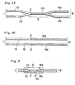
- an optical fiber coupler is constructed by connecting light transmission fibers 1a and 1b, and a rare earth-doped fiber 4 by means of a fused and elongated portion 3, i.e. a fused-stretched portion.
- a pair of optical fibers are used each of which is connected by fusing the ends of fiber cores of the ordinary light transmission fiber 1a or 1b and the rare earth-doped fiber 4.
- the connected section 2 is made by abutting coaxially ends of the core of the single-mode optical fibers 1a and 1b and the core of the rare earth-doped fibers 4a and 4b and heating the abutting ends several times to connect the cores fused.
- the two optical fibers which have been connected of the transmitting and the rare earth doped optical fibers, are aligned at the connected sections 2, brought into contact with each other, then heated to fuse with each other and then stretched until the coupling length is adequate.
- Positioning the two connected sections 2 is made for the purpose of making the propagation constants identical between the two fibers which constitute the fused and elongated portion 3 during stretching. Otherwise, the fibers would not fully couple with each other, thus failing to achieve the multiplexer function.
- the optical fiber coupler shown in Fig. 1A can be fabricated as described above.
- the optical fiber coupler of such a construction is obtained as the two branched ordinary transmitting optical fibers 1a and 1b are connected on one side of the stretched fused and elongated portion 3 as a common single joint fiber and the two rare earth-doped fibers 4 are on the other side.
- the fused and elongated portion 3, which includes the connected section 2 may be located on the rare earth-doped fiber side in the vicinity thereof.
- the fused and elongated portion 3 formed by fusing-stretching is completely located in the rare earth-doped fiber 4 side, and the connected section 2 is in the vicinity thereof.
- the distance between the fused and elongated portion 3 and the connected section 2 of the single mode fiber may be set in a range of about 5 to 15 mm. In case the distance is beyond this range, signal light to enter the rare earth-doped fiber is attenuated before being coupled with the pumping light.
- the fibers which have been jointed by fusing in this manner are mounted on a substrate 5 by means of fastening parts as shown in Fig. 2, and serve for use of an optical coupler.
- optical fiber coupler in general, joining by fusing of fibers having different mode field diameters results in radiation loss at the connecting sections portion due to difference in mode field diameter, but the optical fiber coupler of the present invention is capable of making the mode field diameters almost identical, so that it has advantage to decrease the connection loss.
- mode field diameters are different among the signal light in the single mode fiber, the signal light in the rare earth-doped fiber, the pumping light in the single mode fiber and the pumping light in the rare earth-doped fiber.
- optical fibers of different mode field diameters can be jointed by fusing and then stretching to reduce the diameters, so that the evanescent field of the light which propagates in the fiber increases in both fibers, thereby decreasing the differences in mode field diameters in the joint section on the signal light side and pumping light side and in the rare earth-doped fiber. That is, if the fused connected section 2 of the connected optical fiber as shown in fig.
- the mode field diameters in the fibers 1a and 1b for the signal light and pumping light and in the rare earth-doped fiber 4a can be properly controlled in advance by stretching the fused fiber of the fused and elongated portion 3, thereby effectively decreasing the connection loss of light.
- connection loss can be decreased by forming the fused and elongated portion 3 with the rare earth-doped fiber 4. If the fused and elongated portion 3 (which is a WDM for multiplexing) is provided on the single mode optical fiber 1 side, both signal light and pumping light enter together at the connected section into one end of the rare earth-doped fiber 4, thus making it difficult to match the mode field diameters for each wavelength of the lights in jointing the fibers, resulting in an increased loss.
- pumping light has a wavelength different from the signal light, and the WDM uses a fiber fitted to the transmission wavelength of the pumping light.
- the WDM is made by using a fiber having a different mode field diameter from that of the single mode fiber which transmits the signal light.
- an optical coupling portion in the fused and elongated portion 3 as a common single joint fiber is located on the rare earth-doped fiber 40 side, it is possible to implement proper fuse-connections 2 between the signal light transmitting fiber 1a and the rare earth-doped fiber 4a, and between the pumping light transmitting fiber 1b and the rare earth-doped fiber 4b, individually.
- Connection loss can be adjusted first in fusing and connecting a signal light transmitting optical fibers 1a with a rare earth-doped fiber 4a, and thereafter a pumping light transmitting optical fiber 1b and another rare earth-doped fiber 4b are heated for being fused and connected similarly.
- the two fibers connected as above are brought in parallel contact to each other and heated at the vicinity of the connected sections 2 of the two fibers to be jointed into a common single joint fiber for the joint portion, which include the connecting portions 2 between the transmitting fibers 1a and 1b and rare earth doped fiber 4a and 4b.
- the mode field diameters of both fuse-connected portions 2 increase further because of the stretched fuse-connected portion 3 being located nearer, thereby decreasing the loss.
- Fig. 4 shows an optical fiber amplifier with the optical fiber coupler used as a multiplexer 7, which is provided with single mode optical fibers 1a and 1b on one side (left hand in the figure), while one of said fibers is directly connected with a pumping light source 6 and the other is used to enter signal light.
- This multiplexer 7 is also provided on the other side (right hand in the same figure) with the rare earth-doped fiber 4 (4a), with one end thereof being connected to an optical element such as inline type optical isolator 8.
- the multiplexer 7 itself has the optical fibers 1a and 1b and the rare earth-doped fiber 4 connected thereto, and the optical isolator 8 is connected directly thereto, therefore omitting the two splicing portions 9 and 91 shown in Fig. 7 in the case of the prior art.
- Splice between a rare earth-doped fiber 4 and a single mode optical fiber 1 typically leads to a loss of about 0.1 to 0.2 dB through each splicing joint, i.e. a maximum of 0.4 dB through two joints.
- total loss of light can be restricted to lower than 0.1 dB by decreasing the number of splicing portions.
- the amplifying characteristics such as the gain and the signal to noise ratio are improved.
- there is no need for a fuse-splicing step in forming the optical circuit and it can be unnecessary to secure a space for protective tubes containing the splicing portions in a coupler device.
- a pumping light module may be directly connected as the pumping light source 6 to the pumping light input fiber 1b to the multiplexer 7, then decreasing a loss of the pumping light to improve the amplification characteristics further. This makes it possible to decrease a loss of the pumping light in use and eliminate the splicing step and the splicing portion in making the coupler.
- the signal light enters the multiplexer 7 through the optical fiber 1a , and is multiplexed in the multiplexer 7 with the pumping light entering through the optical fiber 1b.
- the optical coupling section is located on the side of the rare earth-doped fiber 4 of the coupler which makes up the multiplexer 7, so that the entering signal light is transmitted through the single mode optical fiber 1a to the joint of the rare earth-doped fiber 4 while increasing the mode field diameter, thereby to enter the rare earth-doped fiber 4 and is transmitted to the optical coupling section in the fused and elongated portion 3, where the signal light is coupled with the pumping light.
- the signal light is coupled with the pumping light entering from the other rare earth-doped fiber 4b.
- the pumping light pumping the rare earth element ions in the rare earth-doped fiber 4 in the fused and elongated portion 3 to form distribution inversion of the energy level, thereby amplifying the signal light component which enters the inline type optical isolator 8 while only the forward component of the signal light is output.
- the entire optical circuit can reduce in total loss and can increase in amplification characteristics such as amplifying gain and signal to noise ratio.
- the present invention can also be applied to backward pumping amplifier in which pumping light enters from the side of rare earth-doped fiber 4, which is opposite to entrance of pumping light in the case of the forward pumping described above.
- the optical coupler of the invention can be applicable to bi-directional pumping amplifier in which two couplers are formed on both sides of the rare earth-doped fiber 4.
- An embodiment of bi-directional pumping amplifier has a construction, as shown in Fig. 5, in which the optical amplifier as shown in Fig. 4 is provided with another multiplexer 7' connected on the output side of the rare earth-doped fiber 4, with another pumping light source 6' for backward pumping and the optical isolator 8 connected to the other end of the multiplexer 7.
- the operation on the forward excitation side is as described previously.
- Pumping light from the pumping light source 6' for backward pumping enters the rare earth-doped fiber 4 from the multiplexer 7' of the backward pumping side.
- the backward pumping light pumps the rare earth element ions into a higher energy level to generate a revered distribution, thereby amplifying the signal light.
- the signal light which has been amplified by forward pumping and backward pumping, can pass through the inline type optical isolator 8 and is output.
- the optical amplifier shown in Fig. 4 was fabricated to compare characteristics thereof with those of the prior art shown in Fig. 7. As will be seen from the results shown in Fig. 6, the optical amplifier of the present invention has higher gain and lower noise figure in the wavelength band of the signal light, thus providing higher performance than the conventional optical amplifiers.
- the present invention has the following advantages. Since the optical coupler is made by jointing the rare earth-doped fiber and the single mode optical fiber by fusing and stretching the fibers to a desirable diameter in the vicinity of an end of the rare earth-doped fiber, it is not necessary to form any splicing portions individually. Therefore, splicing step in fabricating an optical fiber coupler becomes unnecessary resulting in simplified steps, and moreover the space for accommodating the splicing portions becomes unnecessary, thus possibly to make the optical coupler smaller in size and lower in cost.
- the mode field diameters at the fused connected sections between the signal light transmitting single mode fiber and the rare earth-doped fiber, and the mode field diameters at the connected section between the pumping light transmitting single mode fiber and the rare earth-doped fiber can be matched individually, total loss can be decreased.
- An optical circuit for bi-directional pumping can also be made compact by forming an identical optical fiber coupler also on the other end of the rare earth-doped fiber.
Landscapes
- Physics & Mathematics (AREA)
- Electromagnetism (AREA)
- Optics & Photonics (AREA)
- Engineering & Computer Science (AREA)
- Plasma & Fusion (AREA)
- General Physics & Mathematics (AREA)
- Lasers (AREA)
- Optical Fibers, Optical Fiber Cores, And Optical Fiber Bundles (AREA)
Claims (6)
- Coupleur à fibre optique, contenant des fibres optiques ordinaires (1) et des fibres optiques dopées aux terres rares (4), dont chacune est connectée à l'une desdites fibres optiques ordinaires (1) au moyen d'une section connectée par fusion (2), caractérisé en ce que la section connectée par fusion (2) est située à proximité d'une partie fondue et allongée (3) formée en faisant fondre des deux parties des deux fibres optiques dopées aux terres rares (4).
- Procédé de fabrication d'un coupleur à fibre optique, comprenant la formation d'une paire de fibres optiques, dont chacune est constituée d'une fibre optique ordinaire (1) et d'une fibre optique dopée aux terres rares (4), dont les extrémités sont connectées par fusion, de façon à former des sections connectées par fusion (2) ; la disposition de la paire de fibres optiques parallèlement et en contact l'une avec l'autre, les sections connectées (2) de celles-ci étant alignées ; et le chauffage pour faire fondre une partie des deux fibres optiques dopées aux terres rares (4) en une portion fondue et allongée (3) sous la forme d'une seule fibre réunie, tout en étirant la portion fondue et allongée (3) pour ajuster au diamètre souhaité, de telle sorte que les sections connectées (2) soient situées à proximité de la portion fondue et allongée.
- Utilisation d'un amplificateur optique comprenant le coupleur à fibre optique selon la revendication 1, dans laquelle une lumière de signalisation et une lumière de pompage sont fournies par l'intermédiaire des fibres optiques ordinaires (1) afin d'être multiplexées dans la portion fondue et allongée (3), et un signal amplifié est sorti par l'intermédiaire des fibres dopées aux terres rares (4).
- Utilisation selon la revendication 3, dans laquelle un isolateur optique (8) est connecté à une extrémité des fibres dopées aux terres rares (4), sur le côté sortie.
- Utilisation selon la revendication 3 ou 4, dans laquelle la fibre optique (1) sur le côté entrée est directement connectée à une source de lumière de pompage.
- Ainplificateur optique comprenant deux coupleurs à fibre optique (7, 7') selon la revendication 1, formés des deux côtés d'une fibre dopée aux terres rares (4), dans lequel la lumière de signal est fournie à l'un des coupleurs à fibre optique par l'intermédiaire de l'une de ses fibres optiques ordinaires (la), la lumière de pompage est fournie à l'autre de ses fibres optiques ordinaires (1b), et le signal amplifié est sorti par l'intermédiaire de l'une des fibres optiques ordinaires (1a) de l'autre coupleur à fibre optique.
Applications Claiming Priority (4)
| Application Number | Priority Date | Filing Date | Title |
|---|---|---|---|
| JP36009197 | 1997-12-26 | ||
| JP36009197 | 1997-12-26 | ||
| JP24428598 | 1998-08-31 | ||
| JP24428598A JP3597999B2 (ja) | 1997-12-26 | 1998-08-31 | 光ファイバカップラとその製造方法及びそれを用いた光増幅器 |
Publications (2)
| Publication Number | Publication Date |
|---|---|
| EP0926519A1 EP0926519A1 (fr) | 1999-06-30 |
| EP0926519B1 true EP0926519B1 (fr) | 2005-07-27 |
Family
ID=26536672
Family Applications (1)
| Application Number | Title | Priority Date | Filing Date |
|---|---|---|---|
| EP98124455A Expired - Lifetime EP0926519B1 (fr) | 1997-12-26 | 1998-12-23 | Coupleur à fibre optique, procédé pour sa fabrication et amplificateur optique utilisant celui-ci |
Country Status (5)
| Country | Link |
|---|---|
| US (1) | US6208457B1 (fr) |
| EP (1) | EP0926519B1 (fr) |
| JP (1) | JP3597999B2 (fr) |
| CA (1) | CA2256971C (fr) |
| DE (1) | DE69830973T2 (fr) |
Cited By (1)
| Publication number | Priority date | Publication date | Assignee | Title |
|---|---|---|---|---|
| WO2023211830A1 (fr) * | 2022-04-25 | 2023-11-02 | Schlumberger Technology Corporation | Système et procédé d'assemblage de câbles à fibres optiques |
Families Citing this family (4)
| Publication number | Priority date | Publication date | Assignee | Title |
|---|---|---|---|---|
| US7576909B2 (en) * | 1998-07-16 | 2009-08-18 | Imra America, Inc. | Multimode amplifier for amplifying single mode light |
| JP4237871B2 (ja) * | 1999-05-27 | 2009-03-11 | 京セラ株式会社 | 光ファイバカップラとその製造方法及びこれを用いた光増幅器 |
| CA2363806A1 (fr) * | 2001-11-27 | 2003-05-27 | David R. Rolston | Dispositif tout fibre de commutation/filtrage dynamique de longueurs d'ondes optiques |
| US6995899B2 (en) * | 2002-06-27 | 2006-02-07 | Baker Hughes Incorporated | Fiber optic amplifier for oilfield applications |
Family Cites Families (11)
| Publication number | Priority date | Publication date | Assignee | Title |
|---|---|---|---|---|
| CA2019253C (fr) | 1989-06-23 | 1994-01-11 | Shinya Inagaki | Amplificateur pour fibres optiques |
| JPH03110525A (ja) * | 1989-09-26 | 1991-05-10 | Mitsubishi Cable Ind Ltd | 光増幅器 |
| JPH03123323A (ja) * | 1989-10-06 | 1991-05-27 | Furukawa Electric Co Ltd:The | ファイバカップラー |
| JPH03168726A (ja) * | 1989-11-29 | 1991-07-22 | Showa Electric Wire & Cable Co Ltd | 光分岐結合器 |
| JPH03214125A (ja) * | 1990-01-19 | 1991-09-19 | Fujitsu Ltd | 光ファイバ増幅器 |
| US5171345A (en) * | 1990-08-25 | 1992-12-15 | Kyocera Corporation | Manufacturing method of an optical fiber coupler |
| JP2972366B2 (ja) * | 1991-02-27 | 1999-11-08 | 株式会社フジクラ | 部分エルビウム添加光ファイバカップラ及びその製造方法 |
| GB2256723B (en) * | 1991-06-05 | 1994-05-04 | Marconi Gec Ltd | Fibre optic splicing |
| US5299274A (en) * | 1992-06-25 | 1994-03-29 | Hughes Aircraft Company | Optical fiber laser fusion splicer |
| JPH0659153A (ja) * | 1992-08-11 | 1994-03-04 | Hitachi Cable Ltd | アクティブ型光ファイバカプラ及びその製造方法 |
| GB2278206B (en) * | 1993-05-19 | 1996-04-03 | Northern Telecom Ltd | Polarisation insensitive wavelength multiplexing 2®2 fibre couplers |
-
1998
- 1998-08-31 JP JP24428598A patent/JP3597999B2/ja not_active Expired - Fee Related
- 1998-12-23 US US09/220,874 patent/US6208457B1/en not_active Expired - Fee Related
- 1998-12-23 DE DE69830973T patent/DE69830973T2/de not_active Expired - Lifetime
- 1998-12-23 EP EP98124455A patent/EP0926519B1/fr not_active Expired - Lifetime
- 1998-12-23 CA CA002256971A patent/CA2256971C/fr not_active Expired - Fee Related
Cited By (1)
| Publication number | Priority date | Publication date | Assignee | Title |
|---|---|---|---|---|
| WO2023211830A1 (fr) * | 2022-04-25 | 2023-11-02 | Schlumberger Technology Corporation | Système et procédé d'assemblage de câbles à fibres optiques |
Also Published As
| Publication number | Publication date |
|---|---|
| JP3597999B2 (ja) | 2004-12-08 |
| DE69830973T2 (de) | 2006-04-20 |
| DE69830973D1 (de) | 2005-09-01 |
| CA2256971A1 (fr) | 1999-06-26 |
| CA2256971C (fr) | 2003-09-02 |
| EP0926519A1 (fr) | 1999-06-30 |
| JPH11243244A (ja) | 1999-09-07 |
| US6208457B1 (en) | 2001-03-27 |
Similar Documents
| Publication | Publication Date | Title |
|---|---|---|
| EP0404152B1 (fr) | Amplificateur à fibre optique | |
| CA2020759C (fr) | Dispositif de couplage d'un amplificateur pour fibres dopees a l'erbium | |
| US20080267227A1 (en) | Gain-clamped optical amplifier using double-clad fiber | |
| EP0454865B1 (fr) | Amplificateur optique | |
| US6546168B1 (en) | Integrated isolator fused coupler method and apparatus | |
| JP4237871B2 (ja) | 光ファイバカップラとその製造方法及びこれを用いた光増幅器 | |
| US12431682B2 (en) | Erbium doped fiber isolator components | |
| EP0926519B1 (fr) | Coupleur à fibre optique, procédé pour sa fabrication et amplificateur optique utilisant celui-ci | |
| JPH0325985A (ja) | 光ファイバ増幅器 | |
| US6217204B1 (en) | Optical fiber assembly and light amplification coupler having rare earth doped light amplification medium and related method of making | |
| JP2993493B2 (ja) | 合波機能内蔵光源モジュールとこれを用いた光増幅器および双方向光伝送装置 | |
| US20040076372A1 (en) | Optical amplification structure with an integrated optical system and amplification housing integrating one such structure | |
| JP3495578B2 (ja) | 光ファイバ増幅器 | |
| JP2694014B2 (ja) | 双方向光増幅伝送回路 | |
| JP2744471B2 (ja) | 光増幅伝送回路 | |
| JPH0311320A (ja) | 光増幅伝送回路 | |
| JPH0467130A (ja) | 光ファイバ増幅器及びその製造方法 | |
| JP2003035837A (ja) | 光ファイバカプラとその製法、及びこれを用いた光ファイバ増幅器 | |
| JP2818365B2 (ja) | アクティブ型光ファイバカプラ及びその製造方法 | |
| JP2002359419A (ja) | 光ファイバカプラとこれを用いた光増幅器 | |
| JPH06224497A (ja) | 光増幅器 | |
| JPH08327853A (ja) | 合分波光ファイバカプラ | |
| JP2003043289A (ja) | 光ファイバの接続構造とそれを用いた光増幅器及びase光源 | |
| JP2000105325A (ja) | 光ファイバーコリメータとこれを用いた光モジュール及び光増幅器 | |
| JP2003195094A (ja) | ファイバ型複合機能部品とこれを用いた光ファイバ増幅器及びase光源 |
Legal Events
| Date | Code | Title | Description |
|---|---|---|---|
| PUAI | Public reference made under article 153(3) epc to a published international application that has entered the european phase |
Free format text: ORIGINAL CODE: 0009012 |
|
| 17P | Request for examination filed |
Effective date: 19981223 |
|
| AK | Designated contracting states |
Kind code of ref document: A1 Designated state(s): DE FR GB IT |
|
| AX | Request for extension of the european patent |
Free format text: AL;LT;LV;MK;RO;SI |
|
| AKX | Designation fees paid |
Free format text: DE FR GB IT |
|
| 17Q | First examination report despatched |
Effective date: 20030402 |
|
| GRAP | Despatch of communication of intention to grant a patent |
Free format text: ORIGINAL CODE: EPIDOSNIGR1 |
|
| GRAS | Grant fee paid |
Free format text: ORIGINAL CODE: EPIDOSNIGR3 |
|
| GRAA | (expected) grant |
Free format text: ORIGINAL CODE: 0009210 |
|
| AK | Designated contracting states |
Kind code of ref document: B1 Designated state(s): DE FR GB IT |
|
| REG | Reference to a national code |
Ref country code: GB Ref legal event code: FG4D |
|
| REF | Corresponds to: |
Ref document number: 69830973 Country of ref document: DE Date of ref document: 20050901 Kind code of ref document: P |
|
| ET | Fr: translation filed | ||
| PLBE | No opposition filed within time limit |
Free format text: ORIGINAL CODE: 0009261 |
|
| STAA | Information on the status of an ep patent application or granted ep patent |
Free format text: STATUS: NO OPPOSITION FILED WITHIN TIME LIMIT |
|
| 26N | No opposition filed |
Effective date: 20060428 |
|
| PGFP | Annual fee paid to national office [announced via postgrant information from national office to epo] |
Ref country code: IT Payment date: 20081202 Year of fee payment: 11 |
|
| PGFP | Annual fee paid to national office [announced via postgrant information from national office to epo] |
Ref country code: GB Payment date: 20091112 Year of fee payment: 12 Ref country code: FR Payment date: 20091202 Year of fee payment: 12 |
|
| PGFP | Annual fee paid to national office [announced via postgrant information from national office to epo] |
Ref country code: DE Payment date: 20091223 Year of fee payment: 12 |
|
| PG25 | Lapsed in a contracting state [announced via postgrant information from national office to epo] |
Ref country code: IT Free format text: LAPSE BECAUSE OF NON-PAYMENT OF DUE FEES Effective date: 20091223 |
|
| GBPC | Gb: european patent ceased through non-payment of renewal fee |
Effective date: 20101223 |
|
| REG | Reference to a national code |
Ref country code: FR Ref legal event code: ST Effective date: 20110831 |
|
| PG25 | Lapsed in a contracting state [announced via postgrant information from national office to epo] |
Ref country code: FR Free format text: LAPSE BECAUSE OF NON-PAYMENT OF DUE FEES Effective date: 20110103 |
|
| REG | Reference to a national code |
Ref country code: DE Ref legal event code: R119 Ref document number: 69830973 Country of ref document: DE Effective date: 20110701 |
|
| PG25 | Lapsed in a contracting state [announced via postgrant information from national office to epo] |
Ref country code: GB Free format text: LAPSE BECAUSE OF NON-PAYMENT OF DUE FEES Effective date: 20101223 Ref country code: DE Free format text: LAPSE BECAUSE OF NON-PAYMENT OF DUE FEES Effective date: 20110701 |