EP0926854A2 - Méthodes à égalisation de systèmes de multiplexage d'ondes (WDM) - Google Patents
Méthodes à égalisation de systèmes de multiplexage d'ondes (WDM) Download PDFInfo
- Publication number
- EP0926854A2 EP0926854A2 EP98310276A EP98310276A EP0926854A2 EP 0926854 A2 EP0926854 A2 EP 0926854A2 EP 98310276 A EP98310276 A EP 98310276A EP 98310276 A EP98310276 A EP 98310276A EP 0926854 A2 EP0926854 A2 EP 0926854A2
- Authority
- EP
- European Patent Office
- Prior art keywords
- terminal
- parameter
- channels
- channel
- adm
- Prior art date
- Legal status (The legal status is an assumption and is not a legal conclusion. Google has not performed a legal analysis and makes no representation as to the accuracy of the status listed.)
- Withdrawn
Links
Images


Classifications
-
- H—ELECTRICITY
- H04—ELECTRIC COMMUNICATION TECHNIQUE
- H04J—MULTIPLEX COMMUNICATION
- H04J14/00—Optical multiplex systems
- H04J14/02—Wavelength-division multiplex systems
- H04J14/0221—Power control, e.g. to keep the total optical power constant
-
- H—ELECTRICITY
- H04—ELECTRIC COMMUNICATION TECHNIQUE
- H04J—MULTIPLEX COMMUNICATION
- H04J14/00—Optical multiplex systems
- H04J14/02—Wavelength-division multiplex systems
- H04J14/0201—Add-and-drop multiplexing
-
- H—ELECTRICITY
- H04—ELECTRIC COMMUNICATION TECHNIQUE
- H04J—MULTIPLEX COMMUNICATION
- H04J2203/00—Aspects of optical multiplex systems other than those covered by H04J14/05 and H04J14/07
- H04J2203/0001—Provisions for broadband connections in integrated services digital network using frames of the Optical Transport Network [OTN] or using synchronous transfer mode [STM], e.g. SONET, SDH
- H04J2203/0057—Operations, administration and maintenance [OAM]
- H04J2203/006—Fault tolerance and recovery
Definitions
- the invention is directed to multi-channel communication systems and in particular to methods for equalizing WDM systems.
- High capacity optical transmission networks can use wavelength-division multiplexing (WDM) to increase the information carrying capacity of the optical fiber.
- WDM wavelength-division multiplexing
- the transmitter terminal consists of a like plurality of optical transmitters, typically semiconductor lasers, and an optical wavelength multiplexer, which combines all optical signals into a multi-channel signal before it is launched over the optical fiber.
- Each transmitter operates at a different wavelengths and is modulated with a different data signal, either by directly modulating the laser or by external optical modulation.
- an optical wavelength demultiplexer separates the light received over the fiber according to the wavelength.
- the signal transmitted on each wavelength is then detected by a respective optical receiver.
- the WDM system reach is limited by the attenuation or dispersion of the signal along the optical fiber.
- the reach can be increased by placing optical amplifiers at intermediate points between the terminals. Examples of optical amplifiers are semiconductor optical amplifiers, and rare earth doped fiber amplifiers.
- Optical amplifiers simultaneously amplify all optical signals passing through it, i.e. the multi-channel signal, by amplifying the optical power by a gain.
- optical amplifiers exhibit a wavelength-dependent gain profile, noise profile, and saturation characteristics. Hence, each optical signal experiences a different gain along the transmission path.
- the amplifiers also add noise to the signal, typically in the form of amplified spontaneous emission (ASE), so that the optical signal-to-noise ratio (OSNR) decreases at each amplifier site.
- ASE amplified spontaneous emission
- OSNR optical signal-to-noise ratio
- the OSNR is defined as the ratio of the signal power to the noise power in a reference optical bandwidth.
- the optical signals in the co-propagating channels have different initial waveform distortions and undergo different additional distortions during propagation along the fiber.
- the signals have different power levels, OSNRs, and degrees of distortion when they arrive at the respective receivers, if they had equal power levels at the corresponding transmitters.
- WDM networks and particularly SONET/SDH WDM networks, are widely spread and the custom demand for these networks is growing fast. They provide faster bit rates, and are more flexible in terms of the bandwidth per channel and complexity than the previous single-channel systems.
- Network providers are looking for features such as user-friendly installation, operation and maintenance, and thus, an equalization procedure that is simple and reliable will greatly simplify the set-up and hence reduce the maintenance costs of the communication system.
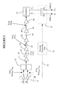
- FIG. 1 shows a block diagram of a four-channel unidirectional wavelength division multiplexed (WDM) transmission link deployed between terminals 11 and 17 , using OSNR equalization according to the above identified patent.
- WDM wavelength division multiplexed
- Terminal 11 comprises transmitters T 1 to T 4 and terminal 17 comprises receivers R 1 to R 4 , connected over optical amplifiers 10 , 20 , 30 , 40 and 50 and fiber spans 10' , 20' , 30' and 40' .
- the optical amplifiers are arranged at a suitable distance from each other, typically 100 km, to compensate for the attenuation of the signal with the distance.
- An optical amplifier amplifies all four signals, as it is well known.
- the lasers of the transmitters T 1 to T 4 are modulated with signals D 1 to D 4 , respectively, to produce optical signals S 1 to S 4 .
- a multiplexer 13 at the site of terminal 11 combines optical signals S 1 - S 4 into a multi-channel signal S, which is amplified in post-amplifier 10 before being launched over the transmission link.
- the multi-channel signal is amplified by pre-amplifier 50 and separated thereafter into signals S' 1 - S' 4 with demultiplexer 15 .
- Each receiver at terminal 17 converts the respective optical signal into an output electrical signal D' 1 - D' 4 , corresponding to input signals D 1 to D 4 .
- the US Patent No. 5,225,922 teaches establishing a telemetry link between two terminals 11 and 17 of a transmission network, for providing the measurements obtained at one terminal to the other.
- the patent indicates that the telemetry link may be provided with a control unit 5 (a microprocessor) that receives the measured input powers of signals S 1 to S 4 and the total output power or OSNR of multi-channel signal S, and adjusts the input power accordingly.
- This method also takes into account the known relative values of the gain for each channel.
- the method disclosed in the above patent has three disadvantages: (1) it equalizes OSNR, which is only one parameter of several that affect the performance of an optical transmission system, (2) measuring the OSNR requires additional equipment, such as an optical spectrum analyzer, outside of the SONET/SDH standards, and (3) it cannot be used to equalize systems where channels with different wavelengths carry traffic with different bit rates, since in such cases each channel has different OSNR requirements.
- Figure 1B shows the optical spectrum of a 4-channel WDM system, showing how the power of the channels varies with the wavelength.
- the co-propagating channels do not have the same performance in terms of bit error rate (BER), because of different component losses, different transmitter and receiver characteristics, different path distortions, and also because the gain and noise of optical amplifiers in the system are channel-dependent.
- BER bit error rate
- the BER is the ratio between the number of erroneous bits counted at a site of interest over the total number of bits received.
- Still another object of the invention is to determine the margins to the failure point of all channels, regardless of their bit rates, which is an important parameter for the customer when deploying the network.
- a method for equalizing the performance of (J) transmission channels of a WDM link connecting a first terminal and a second terminal comprising the steps of, (a) identifying an error threshold level E(j) Fail of an error count indicator E(j) for a signal S(j), the E(j) characterizing the distortion of the signal S(j) between the first and the second terminal, (b) determining an attenuation A(j) of a parameter of interest P(j) of the signal S(j) between the first and the second terminal, (c) repeating steps (a) to (b) for all the J channels of the WDM system, (d) at the first terminal, adjusting the parameter P(j) according to all the attenuations A(j), and (e) repeating step (d) for all the signals S(j) for obtaining substantially equal values of the parameter for all the J signals at the second terminal.
- a method for equalizing a plurality of (J) signals S(j), travelling on a WDM link between a first terminal and a second terminal comprising the steps of, for each channel ⁇ (j) of the WDM link, measuring a distance to failure A(j) for a parameter P(j) of a signal S(j) travelling on the channel ⁇ (j), and adjusting the parameter P(j) at the first terminal for obtaining equal distances to failure for all J channels.
- equalizing the BER value for all channels is preferable to equalization of any other parameter such as OSNR, in that the BER value accounts for all factors that affect the signal in both its electrical and optical states.
- the BER is the ratio between the number of erroneous bits counted at a site of interest over the total number of bits received, giving a measure of all errors introduced into a signal along an entire transmitter-receiver link.
- the method according to the invention performs field equalization to optimize a system in the field, and therefore a higher system margin is used than for equalization based on the average system parameters.
- the method of the present invention does not require necessarily simultaneous access to both the transmitter and receiver ends, but requires physical access to both, one or none of the terminal sites.
- the method could be automated by a software interfacing between the terminals. Requiring simultaneous access to both terminal sites is disadvantageous, because it requires at least two persons communicating over long distances.
- SONET/SDH systems are typically guaranteed in terms of a minimum BER requirement at the system end of life (EOL) and as such the BER measurement is generally available at any receiver site.
- EOL system end of life
- SOL start of life
- the present invention provides a method for equalization of a transmission link in terms of BER, which is a more accurate and easier solution than what prior art provides. Also, this invention provides for measurement of an optimum margin to failure for all the channels at the system SOL.
- the invention is applicable to networks equipped with performance monitoring capabilities. More precisely, the method of the invention is applicable to modern WDM transmission systems, which are in general provided with means for measuring the system BER at various network elements of interest.
- the invention is described next using examples of SONET/SDH WDM transmission systems, but it is to be understood that it may also be applied to other technologies.
- the BER of a SONET/SDH system can be measured using the standard feature of this systems called the performance monitor (PM).
- PM performance monitor
- a block diagram of a typical receiver and a typical transmitter for the transmission systems to which this invention pertains are provided for a better understanding of the invention.
- An optical receiver generally comprises an optical-to-electrical converter 2 , that could be an avalanche photodiode (APD), or a high performance PIN photodiode.
- a data regenerator and clock recovery block 3 extracts the information from the converted signal, based on a threshold level V Th .
- the threshold is selected such as to provide the best error rate for a predetermined signal power level. For example, the levels over V Th are interpreted by the receiver as logic "1"s, while those under, as logic "0"s.
- the errors in regenerated data D 1 ' namely the BER value, are counted using an error detector 4 .
- the error detection in SONET/SDH determines the BER of the respective signal based on the information in the B1 and B2 fields of the transport overhead of the SONET/SDH frame, as well as field B3 of the path overhead for the respective section, line and path.
- the threshold level V Th applied to data regenerator 3 may be adjusted with a controller 6 , so as to obtain BER values under a provisioned value of the respective system.
- the error count and control data are input to a performance monitor 7 , connected to some or all remote elements of the network over a bus 60 .
- a transmitter e.g. T 1 comprises a CW (continuous wave) laser 12 , which is fed into the external modulator 8 and is modulated with e.g. a signal D 1 , to provide the optical signal S 1 .
- this signal is amplified in an EDFA (erbium doped fiber amplifier) 32 , which is provided with a pump laser 42 of a controlled power and wavelength.
- EDFA erbium doped fiber amplifier
- the input, output and backplane power of laser 42 are measured by diverting a fraction (approximately 3%) of the optical signal with taps 31 , 33 , and 34 , respectively, and converting the respective fraction into a corresponding electrical signal with O/E converters 35 , 36 and 37 .
- the measurements are processed by a transmission controller 9 , which in turn adjusts the pump laser 42 and the external modulator 8 , and communicates with the performance monitor 7 and other remote elements of the network over bus 60 .
- the SONET/SDH performance monitor allows the user to remotely measure the channel performance anywhere in the network.
- the equalization of the channels according to the invention is based on equalizing the BER values measured in a point of interest of the transmission link, so that it accounts for all factors affecting the system performance. Since bit errors occur at random times, a minimum number of errors, e.g. 10, is required to estimate the BER for a respective transmission channel within an acceptable confidence level. For example, if the testing interval is chosen to be 1 minute and the bit rate is 2.5 Gb/s, then 15 errors/ minute corresponds to a BER of 10 -10 . In general, the network owner prepares BER-Power curves for all channels at installation, so that these curves are also available for equalization purposes.
- equalization is preferably done at a high BER. Since it is difficult to adjust the system parameters to obtain an exact value for the BER, the failure rate is defined within an order of magnitude for the BER. For example, the point of failure for a channel is defined herein when between 2 and 150 errors are counted in a minute, which corresponds to a BER range from 1.33 x 10 -11 to 10 -9 for a 2.5Gb/s system. It is to be noted that the definition of failure point for the equalization procedure is different from the guaranteed minimum BER requirement of the system in operation.
- Figure 3 illustrates a two-channel unidirectional amplified transmission link connecting transmitters T 1 and T 2 at terminal 11 , with receivers R 1 and R 2 at terminal 17 ; however, the invention equally applies to bi-directional systems with more than two channels.
- the link includes fiber spans 10' , 20' , 30' and 40' connecting optical amplifiers 10 , 20 , 30 , 40 , and 50 for amplifying channels ⁇ (1) and ⁇ (2).
- the link includes fiber spans 10' , 20' , 30' and 40' connecting optical amplifiers 10 , 20 , 30 , 40 , and 50 for amplifying channels ⁇ (1) and ⁇ (2).
- the optical power output by transmitter T 1 on channel ⁇ (1) with P(1) T the loss introduced by span 20' to signal S 1 travelling on channel ⁇ (1) with L(1) S , the power of signal S 1 at the output of amplifier 20 with P(1) A , and the power at the input of receiver R 1 with P(1) R .
- BER(1) is the bit error rate measured after detection of the signal at the output of receiver R 1
- BER(2) is the bit error rate measured after detection of the signal at the output of receiver R 2 .
- Individual notations are used for BER(1) and BER(2) for distinguishing the channels in the process of describing the equal
- the received power margin of a channel is the amount that the received power can be reduced until the channel fails.
- the transmitter power margin of a channel is the amount that the transmitter power of a channel can be reduced until the channel fails.
- the amplifier power margin of a channel is the amount that the output power P(j) A of one or more of the amplifiers can be reduced until the channel fails, and the span margin of a channel is the amount of loss L(j) S that can be added to one or more of the fiber spans until the channel fails, where (j) is the range of the channel between 1 and J, the total number of channels of the WDM system.
- the equalization is performed manually at the transmitter site 11 , based on a the BER curves prepared at installation, that predict how BER varies with the power input to the link.
- the actual readings of the BER(1) and BER(2) may be used, if the network is provided with a communication channel between the transmitter site 11 and the receiver site 17 .
- the communication between the sites may take place along a bidirectional service channel illustrated in Figure 3 by dotted line 22 .
- a network monitoring unit may be connected over this channel for processing the information received from terminals 11 and 17 , or for any other network elements of interest in the respective link.
- Figure 4 shows a flow-chart of the method of the invention for equalizing the system of Figure 3.
- the link is installed/ commissioned to work in the current operating point, without equalization, as shown in step 100 .
- a BER failing point is defined for all channels, corresponding to a BER that is denoted with BER Fail .
- the chosen failure point depends on the bit rate and system requirements.
- the transmitter-receiver pairs are identified, from the transmitter site, namely it is identified which transmitter and receiver communicate along a channel; T 1 and R 1 operate on the frequency of channel ⁇ (1), and T 2 and R 2 operate on the frequency of channel ⁇ (2). This is illustrated in step 110 .
- the output power of both transmitters is set at maximum, P Max ; which is the maximum power of the weakest channel.
- P Max the maximum power of the weakest channel.
- the maximum value P Max or P Max is measured and recorded, as shown in step 115 .
- This measurement takes place under operating conditions of the link, and as such it accounts for the rate of transmission and other parameters of the respective channel.
- the value of the power for which the channel failed is denoted with P(1) Fail .
- An added attenuation A(1) is determined in terms of the power level in step 130 .
- step 135 the power of T 1 is increased back to P Max .
- Attenuations A(1) and A(2) are used to determine the optimum transmitter bias level of all channels, i.e. to select the operation point of the transmitter, shown in steps 150 to 170 for the example of Figure 3.
- A(1), in dB is the added attenuation required to fail channel ⁇ (1)
- A(2), in dB is the added attenuation to fail channel ⁇ (2).
- the stronger channel can now be identified, as shown in steps 150 and 160 to determine the required bias for the transmitters.
- the power of the transmitter of the weak channel is then set to the maximum, and the power in the stronger channel is adjusted so that the difference between the output powers of the two transmitters equals the required power difference.
- the channel ⁇ (1) should be attenuated by: (A(1)-A(2))/2 (in dB) and the channel ⁇ (2) set at full power, as shown in steps 150 and 155 .
- the channel ⁇ (1) should be set at full power and the channel ⁇ (2) should be attenuated by: (A(2)-A(1))/2 (in dB), as shown at 160 and 165 .
- the channel ⁇ (1) requires 10 dB attenuation to fail
- channel ⁇ (2) requires 6 dB attenuation to fail
- 2 dB attenuation on channel ⁇ (1) should be used during operation.
- Step 170 accounts for the case when the two attenuations are equal.
- Figure 5 shows an alternative equalization method based on BER for a WDM system with J (J>2) optical channels propagating in the same direction, called herein the extrapolation method, as shown for example in Figure 7 for four channels.
- the transmission link is installed/commissioned in step 100 , T j - R j pairs are identified in step 105 . and the BER for each channel in the failure point is identified, which depends on the receiver. For example, different values are provided for the receiver of a OC-192 channel than for a receiver for a OC-48 channel. This is shown in step 110 .
- the distance to failure in terms of attenuation for all (J) channels is determined in steps 180 - 205 .
- the power monitors screens of receivers R j may be brought-up at terminal 11 site for reading the power values for all channels.
- the output power is reduced for the first transmitter until this channel fails, i.e. a BER Fail of 10 -8 - 10 -9 is reached at the output of R 1 .
- BER Fail has been selected in the above range as an example only, other targets may be used in a similar way.
- the output power of T j is reset to P Max , as shown in step 190 .
- Monitoring unit 24 determines the distance to failure A(j) for channel (1) according to Eq(1) in step 195 . Steps 185 to 195 are repeated for all (J) channels, as shown by 200 and 205 .
- step 210 When all distances to failure are available, the minimum A(j) is determined in step 210 and denoted with A Min .
- Equalization of channels is next performed by adjusting the output power of all transmitters according to Eq. (5), as shown by step 220 .
- Step 220 is repeated for all J channels, as shown at 225 and 230 .
- decision is made if the channels should be further equalized (fine tuning) or not. Thus, for fine tuning, steps 185 to 240 are repeated with the powers found in step 220 , as indicated in box 235 .
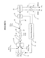
- Figure 6 illustrates an example of a network provided with an external monitoring network.
- the external monitoring network comprises a service channel 22 and a monitoring unit 24 , but the external monitoring may be effected in any other way.
- service channel 22 can be carried through the same fiber with the user traffic, or may be a separate communication network.
- the equalization for the link between transmitter terminal 11 and receiver terminal 17 is performed automatically, in that the BER measured in the failing point of the channels and the powers of the transmitters are processed by monitoring unit 24 which calculates the attenuations A(1) or A(2) and adjusts the operating point of transmitters T 1 and T 2 accordingly.
- the service channel 22 conveys the measured BERs to unit 24 processor that calculates the power margins and performs the required adjustments of the power for each transmitter.
- the power margin in a point of interest may be measured using attenuators.
- attenuators may be used for the case when the WDM system is equipped with fixed power transmitters.
- VOA 21 For measuring the received power margin of the entire transmission link between terminals 11 and 17 , a variable-optical-attenuator (VOA) 21 is connected just before demultiplexer 15. The attenuation of the VOA 21 for channel ⁇ (1) is increased until the BER(1) reaches the failure condition denoted with BER Fail . The transmitter powers are adjusted until all channels fail at the same VOA attenuation, in which case all channels will have the same power margin.
- amplifier power margin can be measured by monitoring the BER at the output of a channel as the power of one or more amplifiers is reduced.
- the span margin can be measured by inserting a VOA into one or more spans.
- the transmitter power margin can be measured by setting all transmit output powers at maximum, then reducing the powers, one channel at a time until that channel fails. The measured distance to failure, in terms of attenuation or power level, is then used to select the biasing levels for the transmitters.
- the various margins are very useful in that they give the network owner a good measure of how much more equipment/fiber can be added to the link, or how the link may be reconfigured or upgraded.
- the presence of the external monitoring network simplifies the adjustment, in that all power values measured for the system and the corresponding BERs may be collected in the point of interest, and also, the adjustment of any network element may be effected remotely by the monitoring unit 24 based on the data collected from the elements of the link.
- the transmitter power adjustment may be done manually or automatically, using a model that predicts how the BER varies with the input power, while incorporating other relevant system constraints.
- the transmitter power margins of the co-propagating channels can be equalized automatically, as the measurements can be effected by the power monitor.
- the BER of all the channels can be equalized by adjusting the transmitted powers of the various channels taking into account the transmitter dynamic ranges, the system input power dynamic range, and the measured margins to failure.
- the margins for the new values of input powers can be re-measured and the input powers can be iteratively adjusted to obtain a more accurate bias point. For most cases, adequate equalization can be obtained by going through only one or two iterations.
- FIG. 7 depicts a schematic diagram of a typical WDM transmission link with multiple terminals.
- An Add/Drop multiplexer (ADM) 65 drops signal S 1 ' travelling on channel ⁇ (1) from the multi-channel signal S.
- Receiver R 1 is located at the site of ADM 65 in this example.
- a fifth signal, S 5 which has the same band as signal S 1 , is added on channel ⁇ 1 to multi-channel signal S, and transmitted from ADM 65 to terminal 17 where it is detected by a receiver R 5 .
- Equalization of a network as shown in Figure 7 or a network with any number of channels to be dropped/added at the ADM site may be performed using the principle illustrated in Figure 5 and disclosed in the accompanying text.
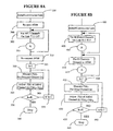
- FIG. 8A A first way of equalizing performance of this network is shown in Figure 8A.
- all (K) channels to be dropped at the ADM 65 site here designated with (k) are connected through the ADM coupler so as to by-pass the ADM. More precisely, the drop port and the add port of the coupler are connected using a short patch-cord for each of the channels to be dropped, so that the channels travel all the way from terminal 11 to terminal 17 .
- channel S 1 dropped at ADM 65 is rather connected to by-pass the ADM to arrive at terminal 17 . This is shown in step 300 .
- Steps 302 and 305 indicate that the procedure marked in Figure 5 with A, performed for equalizing the performance of J end-to-end channels (four in this example) are now carried for signals S 1 -S 4 transmitted by terminal 11 .
- ADM 65 is reconnected so that the K drop channels end at that site, as shown in step 310 .
- channel S 1 is reconnected to the drop port of ADM 65 .
- each drop channels (k) is measured in step 320 , and the channel is added back at the ADM site, with the transmit power equal to the received power, step 325 .
- Steps 320 and 325 are repeated for all dropped channels, as shown at 315-335 .
- the power of added signal S 5 transmitted over channel ⁇ 1 is adjusted to be equal to the power of signal S 1 ' measured at the ADM site.
- Figure 8B shows another variant of how the system of Figure 7 can be equalized.
- optical paths (a), (b) and (c) shown on this figure are considered namely: path (a), includes M channels directly connecting terminal 11 with terminal 17 , passing through ADM 65; path (b) includes K channels connecting terminal 11 with ADM 65 , and dropped at the ADM site; and path (c) includes K channels added at ADM 65 , between ADM site and terminal 17 .
- the number of channels dropped and added as equal.
- FIG. 8B shows step 100 , whereby the link between terminals 11 and 17 is installed/commissioned, followed by equalization of all M direct (end-to-end) channels on link (a), as shown in steps 400 and 405 .
- steps 410 and 415 channels K dropped at ADM 65 are equalized using the same procedure as in Figure 5. Then, the power of each of the K received (dropped) channels is measured at the ADM site, as shown in step 425 .
- the transmit power of each added channel P(k) a is set equal to the power of the corresponding dropped channel P(k) d , shown in step 425 .
- FIG. 8C Another method of equalization of performance for the link of Figure 7 is disclosed next in connection with Figure 8C.
- the procedure in Figure 5 is applied to optical paths (a), for all M direct channels between terminals 11 and 17 , in steps 500 - 505 , then to path (b) including all K dropped channels, in steps 510-515 and then to path (c) including all K added channels, in steps 520-525 , by considering the channels added back to the link through the ADM coupler as extra channels when using Eq(5).
- external monitoring network iterates the steps above until the powers of all channels converge to within predetermined guidelines. Since one or more channels may be operating error-free before equalization, the performance of these channels is degraded during equalization to measure the received power margin, transmitted power margin, amplifier power margin, or span margin.
- Monitoring unit 24 equalizes the BER at the receivers by adjusting the transmitter powers, either by reducing the power of the strongest transmitter, or by increasing the power of the weaker transmitters.
- failure point is a user pre-defined point, so that a higher BER value may be selected for defining the failing point, to operate all channels above it.
- Another solution is to attenuate the transmitter output power of all other channels, which are initially running at a BER lower than the failure point. In this way, the performance of the failed channel(s) is brought back in the vicinity of the failure point. The output power of these transmitters is then used as the initial setting.
- Another way to define failure of a channel is to use a loss-of signal (LOS) or signal-degradation (SD) alarms at the receiver.
- This alternative method has the advantage that the LOS or SD alarm are raised automatically and immediately, so it gives a faster measure of the channel failure point.
- this second alternative has some drawbacks, such as: (1) the equalization would be performed with the channels functioning away from the operating point so that the results are less accurate, (2) it requires a larger transmitter power dynamic range to reach the failure point, and (3) the LOS or SD alarm are not as accurate a measure of system performance as is the BER.
Landscapes
- Engineering & Computer Science (AREA)
- Computer Networks & Wireless Communication (AREA)
- Signal Processing (AREA)
- Optical Communication System (AREA)
- Mobile Radio Communication Systems (AREA)
Applications Claiming Priority (2)
| Application Number | Priority Date | Filing Date | Title |
|---|---|---|---|
| US08/997,822 US6115157A (en) | 1997-12-24 | 1997-12-24 | Methods for equalizing WDM systems |
| US997822 | 1997-12-24 |
Publications (2)
| Publication Number | Publication Date |
|---|---|
| EP0926854A2 true EP0926854A2 (fr) | 1999-06-30 |
| EP0926854A3 EP0926854A3 (fr) | 2002-07-24 |
Family
ID=25544437
Family Applications (1)
| Application Number | Title | Priority Date | Filing Date |
|---|---|---|---|
| EP98310276A Withdrawn EP0926854A3 (fr) | 1997-12-24 | 1998-12-15 | Méthodes à égalisation de systèmes de multiplexage d'ondes (WDM) |
Country Status (2)
| Country | Link |
|---|---|
| US (2) | US6115157A (fr) |
| EP (1) | EP0926854A3 (fr) |
Cited By (15)
| Publication number | Priority date | Publication date | Assignee | Title |
|---|---|---|---|---|
| FR2811836A1 (fr) * | 2000-07-10 | 2002-01-18 | Advantest Corp | Appareil de mesure d'une caracteristique optique, procede et programme informatique de mise en oeuvre |
| EP1176747A1 (fr) * | 2000-07-27 | 2002-01-30 | Sagem S.A. | Procédé de régulation de puissance de longueurs d'ondes entrantes injectées dans un signal optique modulé |
| GB2366925A (en) * | 2000-09-13 | 2002-03-20 | Marconi Comm Ltd | Power control and equalisation in an optical WDM system |
| WO2002080426A1 (fr) * | 2001-03-29 | 2002-10-10 | Marconi Communications Limited | Systeme de commande de puissance par multiplexage a division de longueur d'onde |
| WO2002071670A3 (fr) * | 2001-03-01 | 2002-12-27 | Lightscape Networks Ltd | Procede et systeme de manipulation de signaux optiques |
| EP1282255A1 (fr) * | 2001-07-19 | 2003-02-05 | Sameh A. Sabet | Systeme et procedé pour optimisation automatique des systèmes de télécommunications optiques |
| EP1343269A1 (fr) * | 2002-03-04 | 2003-09-10 | Broadcom Corporation | Procédé et dispositif pour la détection de perte de signal avec une charge capacitive réduite pour les signaux d'entrée |
| EP1156608A3 (fr) * | 2000-05-17 | 2004-02-18 | Siemens Aktiengesellschaft | Methode de réglage du rapport Signal sur Bruit d'un signal optique à insertion/extraction |
| US6735725B1 (en) | 2000-09-29 | 2004-05-11 | Nortel Networks Limited | Method and apparatus for performance management of a multiplexed transmission system |
| EP1089477A3 (fr) * | 1999-09-28 | 2005-03-16 | Fujitsu Limited | Procédé de contrôle de la déviation en puissance optique entre longueurs d'ondes, égalisateur et amplificateur optiques utilisant ladite méthode |
| EP1349310A3 (fr) * | 2002-03-29 | 2005-11-16 | Nortel Networks Limited | Equilibrage de puissance des réseaux optiques DWDM |
| EP1134925A3 (fr) * | 2000-03-14 | 2006-01-04 | Lucent Technologies Inc. | Système de transmission optique incluant l'optimisation des performances |
| EP2053771A1 (fr) * | 2007-10-26 | 2009-04-29 | Alcatel Lucent | Procédé d'optimisation de l'amplification optique dans un réseau optique |
| US7693423B2 (en) | 2002-06-11 | 2010-04-06 | Ericsson Ab | Maximising power in optical communication networks |
| EP3051720A4 (fr) * | 2013-09-24 | 2017-06-07 | Nec Corporation | Appareil de transport, système de transport, procédé de transport, et support d'informations sur lequel est mémorisé un programme |
Families Citing this family (107)
| Publication number | Priority date | Publication date | Assignee | Title |
|---|---|---|---|---|
| US6914717B1 (en) | 1996-12-23 | 2005-07-05 | Xtera Communications, Inc. | Multiple wavelength pumping of raman amplifier stages |
| US6052393A (en) | 1996-12-23 | 2000-04-18 | The Regents Of The University Of Michigan | Broadband Sagnac Raman amplifiers and cascade lasers |
| US6631018B1 (en) * | 1997-08-27 | 2003-10-07 | Nortel Networks Limited | WDM optical network with passive pass-through at each node |
| US6359708B1 (en) * | 1997-09-18 | 2002-03-19 | Lucent Technologies Inc. | Optical transmission line automatic power reduction system |
| US6115157A (en) * | 1997-12-24 | 2000-09-05 | Nortel Networks Corporation | Methods for equalizing WDM systems |
| JP3166695B2 (ja) * | 1998-01-05 | 2001-05-14 | 日本電気株式会社 | 波長分割多重送信装置 |
| JP3829962B2 (ja) * | 1998-01-22 | 2006-10-04 | 富士通株式会社 | 光アッテネータ並びに該光アッテネータを備えたシステム、光増幅器及び端局装置 |
| JP3270385B2 (ja) * | 1998-02-12 | 2002-04-02 | 富士通株式会社 | 光通信システムにおける誤動作防止用ガード装置 |
| JP4011187B2 (ja) * | 1998-03-20 | 2007-11-21 | 富士通株式会社 | 光合分波装置 |
| US6597493B2 (en) | 2000-05-05 | 2003-07-22 | The Regents Of The University Of Michigan | Nonlinear fiber amplifiers used for a 1430-1530nm low-loss window in optical fibers |
| US6868237B2 (en) | 1998-04-24 | 2005-03-15 | Lightpointe Communications, Inc. | Terrestrial optical communication network of integrated fiber and free-space links which requires no electro-optical conversion between links |
| US6239888B1 (en) | 1998-04-24 | 2001-05-29 | Lightpointe Communications, Inc. | Terrestrial optical communication network of integrated fiber and free-space links which requires no electro-optical conversion between links |
| US6222668B1 (en) * | 1998-05-08 | 2001-04-24 | Nortel Networks Limited | Fast loss of signal (LOS) detection for bidirectional optical amplifiers |
| US6574037B2 (en) | 1998-06-16 | 2003-06-03 | Xtera Communications, Inc. | All band amplifier |
| JP2000031900A (ja) * | 1998-07-08 | 2000-01-28 | Fujitsu Ltd | 光ファイバ通信のための方法並びに該方法の実施に使用する端局装置及びシステム |
| US6215565B1 (en) * | 1998-07-27 | 2001-04-10 | Mci Communications Corporation | Method of and system for diagnosing optical system failures |
| US6317231B1 (en) * | 1998-09-04 | 2001-11-13 | Lucent Technologies Inc. | Optical monitoring apparatus and method for network provisioning and maintenance |
| US6816681B2 (en) * | 1998-09-24 | 2004-11-09 | Nortel Networks Limited | Analogous channel method for performance monitoring and equalization in optical networks |
| US6128330A (en) | 1998-11-24 | 2000-10-03 | Linex Technology, Inc. | Efficient shadow reduction antenna system for spread spectrum |
| US6446028B1 (en) * | 1998-11-25 | 2002-09-03 | Keynote Systems, Inc. | Method and apparatus for measuring the performance of a network based application program |
| US7181138B1 (en) * | 1998-12-14 | 2007-02-20 | Tellabs Operations, Inc. | Optical network connection test apparatus and methods |
| US6721508B1 (en) | 1998-12-14 | 2004-04-13 | Tellabs Operations Inc. | Optical line terminal arrangement, apparatus and methods |
| US6433904B1 (en) * | 1999-07-27 | 2002-08-13 | Sycamore Networks, Inc. | Method and apparatus for improving transmission performance over wavelength division multiplexed optical communication links using forward error correction coding |
| US6697577B1 (en) * | 1999-11-01 | 2004-02-24 | Nortel Networks Limited | Method and apparatus for in-service optimization of the performance of an optical transmission system |
| WO2001039415A1 (fr) * | 1999-11-24 | 2001-05-31 | Centerpoint Broadband Technologies Inc. | Unite de commande de puissance intelligente |
| US6580531B1 (en) * | 1999-12-30 | 2003-06-17 | Sycamore Networks, Inc. | Method and apparatus for in circuit biasing and testing of a modulated laser and optical receiver in a wavelength division multiplexing optical transceiver board |
| US6763195B1 (en) * | 2000-01-13 | 2004-07-13 | Lightpointe Communications, Inc. | Hybrid wireless optical and radio frequency communication link |
| US20010046350A1 (en) * | 2000-02-25 | 2001-11-29 | Tedesco James M. | Configurable Wavelength routing device |
| US6449068B1 (en) * | 2000-03-06 | 2002-09-10 | Lightchip, Inc. | Optical power managed network node for processing dense wavelength division multiplexed optical signals |
| JP2002158636A (ja) * | 2000-03-29 | 2002-05-31 | Hitachi Ltd | 光伝送装置およびその監視システム |
| US7522835B1 (en) * | 2000-04-17 | 2009-04-21 | Ciena Corporation | Method of testing bit error rates for a wavelength division multiplexed optical communication system |
| WO2001082516A1 (fr) * | 2000-04-24 | 2001-11-01 | Lucent Technologies Inc. | Egalisation du gain dans des reseaux mrl dense |
| US6701089B1 (en) * | 2000-06-30 | 2004-03-02 | Nortel Networks Limited | Over-equalization for multi-span wavelength division multiplexed fiber optic communication systems |
| WO2002009299A2 (fr) * | 2000-07-21 | 2002-01-31 | Sycamore Networks, Inc. | Procede et dispositif pour accroitre la distance de transmission optique a l'aide de multiples preaccentuations dans un systeme dwdm amplifie optiquement |
| KR100340203B1 (ko) * | 2000-09-19 | 2002-06-15 | 오길록 | 파장분할 다중화 방식 광전송 시스템의 광성능 감시장치 |
| US6961524B1 (en) * | 2000-09-22 | 2005-11-01 | Nortel Networks Limited | WDM channel equalization in add/drop-capable optical networks |
| US6961525B2 (en) * | 2000-11-17 | 2005-11-01 | Sycamore Networks, Inc. | Method for channel balance |
| US6721509B2 (en) * | 2000-12-05 | 2004-04-13 | Avanex Corporation | Self-adjusting optical add-drop multiplexer and optical networks using same |
| CA2365373A1 (fr) * | 2000-12-28 | 2002-06-28 | Jeffrey K. Emery | Methodes d'egalisation pour systeme dwdm |
| JP3907157B2 (ja) * | 2001-01-12 | 2007-04-18 | 株式会社ルネサステクノロジ | 信号処理用半導体集積回路および無線通信システム |
| JP3979485B2 (ja) * | 2001-01-12 | 2007-09-19 | 株式会社ルネサステクノロジ | 信号処理用半導体集積回路および無線通信システム |
| US6904241B2 (en) * | 2001-02-06 | 2005-06-07 | Ciena Corporation | Power balanced optical add multiplexer and power balancing methods therefore |
| US6885825B2 (en) * | 2001-02-06 | 2005-04-26 | Ciena Corporation | Power balanced optical add/drop multiplexer and power balancing methods therefore |
| US6333798B1 (en) | 2001-02-13 | 2001-12-25 | Seneca Networks, Inc. | Bidirectional WDM optical communication network |
| US6907197B2 (en) * | 2001-03-12 | 2005-06-14 | Nortel Networks Limited | Method and apparatus for measuring and estimating optical signal to noise ratio in photonic networks |
| US6532101B2 (en) | 2001-03-16 | 2003-03-11 | Xtera Communications, Inc. | System and method for wide band Raman amplification |
| DE10112805B4 (de) * | 2001-03-16 | 2006-11-30 | Siemens Ag | Optisches Übertragungssystem mit verbessertem Signal-zu-Rausch-Verhalten |
| US6810214B2 (en) | 2001-03-16 | 2004-10-26 | Xtera Communications, Inc. | Method and system for reducing degradation of optical signal to noise ratio |
| DE10113303B4 (de) * | 2001-03-19 | 2004-01-29 | Siemens Ag | Verfahren zur Verbesserung und Vergleichmäßigung der Datenübertragungsqualität in einem WDM-System und WDM-System zur Durchführung des Verfahrens |
| US6871020B1 (en) * | 2001-04-03 | 2005-03-22 | At&T Corp. | Power spectrum monitoring and management in a wavelength division multiplexed network |
| US6889009B2 (en) * | 2001-04-16 | 2005-05-03 | Lightpointe Communications, Inc. | Integrated environmental control and management system for free-space optical communication systems |
| US7133125B2 (en) * | 2001-04-23 | 2006-11-07 | Circadiant Systems, Inc. | Automated system and method for determining the sensitivity of optical components |
| US7298463B2 (en) * | 2001-04-23 | 2007-11-20 | Circadiant Systems, Inc. | Automated system and method for optical measurement and testing |
| US6614589B2 (en) | 2001-05-09 | 2003-09-02 | Ciena Corporation | Method and system for controlling amplifier power in an optical communications network |
| US6600596B2 (en) * | 2001-05-09 | 2003-07-29 | Ciena Corporation | Method and system for controlling amplifier power in an optical communications network having add/drop capability |
| US7242863B2 (en) | 2001-05-09 | 2007-07-10 | Ciena Corporation | Method and system for coordinating and utilizing channel power information in an optical communications network |
| WO2002091027A2 (fr) * | 2001-05-09 | 2002-11-14 | Ciena Corporation | Procede et systeme de regulation de puissance d'amplificateur dans un reseau de communication optique dote d'une fonction d'insertion-extraction |
| US6559985B1 (en) | 2001-05-09 | 2003-05-06 | Ciena Corporation | Method and system for determining channel power in an optical communications network |
| US7483639B2 (en) * | 2001-05-10 | 2009-01-27 | Fujitsu Limited | Method and system for transmitting information in an optical communication system using distributed amplification |
| US7200344B1 (en) | 2001-05-10 | 2007-04-03 | Fujitsu Limited | Receiver and method for a multichannel optical communication system |
| US6636666B2 (en) | 2001-05-14 | 2003-10-21 | University Of Iowa Research Foundation | Optical power equalizer |
| US6943937B2 (en) * | 2001-05-17 | 2005-09-13 | Avanex Corporation | Optical amplifier performance controller and method of use |
| US20030016410A1 (en) * | 2001-07-18 | 2003-01-23 | Innovance Networks | Method for engineering connections in a dynamically reconfigurable photonic switched network |
| WO2002103948A1 (fr) * | 2001-06-13 | 2002-12-27 | Fujitsu Limited | Systeme de communication optique |
| US7941047B2 (en) * | 2001-07-18 | 2011-05-10 | Alcatel-Lucent Usa Inc. | Method for engineering connections in a dynamically reconfigurable photonic switched network |
| US6877117B1 (en) * | 2001-07-27 | 2005-04-05 | Ciena Corporation | Optical signal receiver and method with decision threshold adjustment based on a relative percentage error indicator |
| US6885828B1 (en) | 2001-07-27 | 2005-04-26 | Ciena Corporation | Optical signal receiver and method with decision threshold adjustment based on a total percentage error indicator field of the invention |
| US6587259B2 (en) | 2001-07-27 | 2003-07-01 | Xtera Communications, Inc. | System and method for controlling noise figure |
| US20030053750A1 (en) * | 2001-09-20 | 2003-03-20 | Yang William (Wei) | Dynamic channel power equalizer based on VPG elements |
| US6594071B1 (en) | 2001-10-02 | 2003-07-15 | Xtera Communications, Inc. | Method and apparatus for amplifier control |
| WO2003030427A1 (fr) * | 2001-10-03 | 2003-04-10 | Tejas Networks India Pvt. Ltd. | Reduction du rapport signal optique sur bruit (osnr) d'un systeme de transmission a multiplexage par repartition en longueur d'onde dense (dwdm) amplifie par voie optique |
| WO2003030428A1 (fr) * | 2001-10-03 | 2003-04-10 | Tejas Networks India Pvt. Ltd. | Systeme pour ameliorer le rapport osnr d'un systeme de transmission dwdm |
| US20030090765A1 (en) * | 2001-11-09 | 2003-05-15 | Neff Brian W. | Free-space optical communication system |
| FR2832274B1 (fr) * | 2001-11-15 | 2006-08-25 | Alcatel Optronics | Procede de controle dynamique d'un module optique |
| US7233432B2 (en) * | 2001-12-20 | 2007-06-19 | Xtera Communications, Inc. | Pre-emphasized optical communication |
| US6819479B1 (en) | 2001-12-20 | 2004-11-16 | Xtera Communications, Inc. | Optical amplification using launched signal powers selected as a function of a noise figure |
| US7068932B2 (en) * | 2002-01-17 | 2006-06-27 | Tropic Networks Inc. | Method and system for automatic initialization of an optical network |
| US6825973B1 (en) | 2002-03-15 | 2004-11-30 | Xtera Communications, Inc. | Reducing leading edge transients using co-propagating pumps |
| US7197245B1 (en) | 2002-03-15 | 2007-03-27 | Xtera Communications, Inc. | System and method for managing system margin |
| US6819478B1 (en) | 2002-03-15 | 2004-11-16 | Xtera Communications, Inc. | Fiber optic transmission system with low cost transmitter compensation |
| US6778321B1 (en) | 2002-03-15 | 2004-08-17 | Xtera Communications, Inc. | Fiber optic transmission system for a metropolitan area network |
| AU2003222969A1 (en) * | 2002-04-12 | 2003-10-27 | Azea Networks Limited | Transmission system |
| US7155123B2 (en) * | 2002-05-10 | 2006-12-26 | Lucent Technologies Inc. | Method and apparatus for locating faults in an optical network |
| US20040005151A1 (en) * | 2002-07-02 | 2004-01-08 | Donald Pitchforth | Gateway network element for providing automatic level control and error monitoring |
| US20040208577A1 (en) * | 2002-07-23 | 2004-10-21 | Sycamore Networks, Inc. | Methods for in-service wavelength upgrade and system performance optimization in WDM optical networks |
| JP2004297714A (ja) * | 2003-03-28 | 2004-10-21 | Fujitsu Ltd | 多方向光分岐装置 |
| US7522846B1 (en) * | 2003-12-23 | 2009-04-21 | Nortel Networks Limited | Transmission power optimization apparatus and method |
| US7472320B2 (en) * | 2004-02-24 | 2008-12-30 | International Business Machines Corporation | Autonomous self-monitoring and corrective operation of an integrated circuit |
| JP4625372B2 (ja) * | 2005-05-26 | 2011-02-02 | 富士通株式会社 | 光伝送装置およびその導通試験方法並びに光伝送システム |
| US7609981B2 (en) * | 2005-09-07 | 2009-10-27 | Alcatel-Lucent Usa Inc. | Deliberate signal degradation for optimizing receiver control loops |
| JP4985762B2 (ja) * | 2007-02-27 | 2012-07-25 | 富士通株式会社 | Wdm伝送装置 |
| US7826748B2 (en) * | 2007-03-23 | 2010-11-02 | Ciena Corporation | Systems and methods for adaptive gain control to compensate OSNR penalty caused by side-lobe of MEMS-based reconfigurable optical add-drop multiplexers |
| US8280257B2 (en) * | 2007-03-23 | 2012-10-02 | Ciena Corporation | Systems and methods for side-lobe compensation in reconfigurable optical add-drop multiplexers |
| US20080292312A1 (en) * | 2007-05-21 | 2008-11-27 | Tellabs Petaluma, Inc. | Method and apparatus for determining optical path attenuation between passive optical network nodes |
| US20090245810A1 (en) * | 2008-03-25 | 2009-10-01 | Nec Laboratories America, Inc. | Dynamic Signal Equalization in Optical Transmission Systems |
| US8045852B2 (en) * | 2008-04-23 | 2011-10-25 | Alcatel Lucent | Channel balancing algorithm |
| CN101841373B (zh) * | 2009-03-19 | 2013-04-24 | 华为技术有限公司 | 调节光功率的方法及装置 |
| JP5633266B2 (ja) * | 2010-09-15 | 2014-12-03 | 富士通株式会社 | Wdm光伝送システムおよびその制御方法 |
| US20140029582A1 (en) * | 2012-07-27 | 2014-01-30 | Qualcomm Incorporated | Method and apparatus for a power control mechanism |
| US8989595B2 (en) * | 2013-06-19 | 2015-03-24 | Fujitsu Limited | Mitigation of optical signal to noise ratio degradation arising from polarization dependent loss |
| US9768902B2 (en) * | 2015-10-22 | 2017-09-19 | Ciena Corporation | Control systems and methods for spectrally overlapped flexible grid spectrum using a control bandwidth |
| US10014971B2 (en) | 2016-09-12 | 2018-07-03 | Fujitsu Limited | Credit based approach to calculating optical paths |
| US9893804B1 (en) * | 2016-09-12 | 2018-02-13 | Fujitsu Limited | Credit based approach to optimizing optical transmission |
| CN106506093B (zh) * | 2016-11-28 | 2019-09-06 | 中车株洲电力机车研究所有限公司 | 一种fso通信系统 |
| US10187149B2 (en) * | 2017-05-05 | 2019-01-22 | Cisco Technology, Inc. | Downstream node setup |
| WO2019044604A1 (fr) * | 2017-08-29 | 2019-03-07 | 日本電気株式会社 | Dispositif de transmission optique et procédé de commande de spectre |
| US11536916B1 (en) * | 2021-05-10 | 2022-12-27 | Amazon Technologies, Inc. | Pathloss optimization for optical systems |
Family Cites Families (11)
| Publication number | Priority date | Publication date | Assignee | Title |
|---|---|---|---|---|
| US4927266A (en) * | 1987-03-30 | 1990-05-22 | Anritsu Corporation | Optical signal generating apparatus and optical power meter calibrating system using the same |
| US5225922A (en) * | 1991-11-21 | 1993-07-06 | At&T Bell Laboratories | Optical transmission system equalizer |
| JPH06224853A (ja) * | 1993-01-28 | 1994-08-12 | Ando Electric Co Ltd | 光pll回路 |
| JP3373332B2 (ja) * | 1995-05-26 | 2003-02-04 | Kddi株式会社 | プリエンファシス方式光波長多重通信方法および装置 |
| GB9516017D0 (en) * | 1995-08-04 | 1995-10-04 | Stc Submarine Systems Ltd | Optical level control in wavelength add-drop multiplexing branching units |
| DE19708846A1 (de) * | 1997-03-05 | 1998-09-17 | Gruenenthal Gmbh | Neue Benzoxazindionderivate, Verfahren zu ihrer Herstellung und ihre Verwendung |
| JPH118590A (ja) * | 1997-04-25 | 1999-01-12 | Oki Electric Ind Co Ltd | 光伝送システム及びその監視制御方法 |
| US6008916A (en) * | 1997-09-19 | 1999-12-28 | Nortel Networks Corporation | Distortion penalty measurement technique in optical systems based on signal level adjustment |
| US6069718A (en) * | 1997-09-19 | 2000-05-30 | Nortel Networks Corporation | Distortion penalty measurement procedure in optical systems using noise loading |
| US6040933A (en) * | 1997-12-19 | 2000-03-21 | Nortel Networks Corporation | Method and apparatus for channel equalization in wavelength division multiplexed systems |
| US6115157A (en) * | 1997-12-24 | 2000-09-05 | Nortel Networks Corporation | Methods for equalizing WDM systems |
-
1997
- 1997-12-24 US US08/997,822 patent/US6115157A/en not_active Expired - Lifetime
-
1998
- 1998-12-15 EP EP98310276A patent/EP0926854A3/fr not_active Withdrawn
-
2000
- 2000-04-27 US US09/559,562 patent/US6219162B1/en not_active Expired - Lifetime
Cited By (21)
| Publication number | Priority date | Publication date | Assignee | Title |
|---|---|---|---|---|
| EP1089477A3 (fr) * | 1999-09-28 | 2005-03-16 | Fujitsu Limited | Procédé de contrôle de la déviation en puissance optique entre longueurs d'ondes, égalisateur et amplificateur optiques utilisant ladite méthode |
| EP1134925A3 (fr) * | 2000-03-14 | 2006-01-04 | Lucent Technologies Inc. | Système de transmission optique incluant l'optimisation des performances |
| EP1156608A3 (fr) * | 2000-05-17 | 2004-02-18 | Siemens Aktiengesellschaft | Methode de réglage du rapport Signal sur Bruit d'un signal optique à insertion/extraction |
| FR2811836A1 (fr) * | 2000-07-10 | 2002-01-18 | Advantest Corp | Appareil de mesure d'une caracteristique optique, procede et programme informatique de mise en oeuvre |
| EP1176747A1 (fr) * | 2000-07-27 | 2002-01-30 | Sagem S.A. | Procédé de régulation de puissance de longueurs d'ondes entrantes injectées dans un signal optique modulé |
| FR2812485A1 (fr) * | 2000-07-27 | 2002-02-01 | Sagem | Procede de regulation de puissance de longueurs d'ondes entrantes injectees dans un signal optique module |
| GB2366925A (en) * | 2000-09-13 | 2002-03-20 | Marconi Comm Ltd | Power control and equalisation in an optical WDM system |
| US6735725B1 (en) | 2000-09-29 | 2004-05-11 | Nortel Networks Limited | Method and apparatus for performance management of a multiplexed transmission system |
| WO2002071670A3 (fr) * | 2001-03-01 | 2002-12-27 | Lightscape Networks Ltd | Procede et systeme de manipulation de signaux optiques |
| US7280768B2 (en) | 2001-03-01 | 2007-10-09 | Eci Telecom Ltd. | Method and system for handling optical signals |
| WO2002080426A1 (fr) * | 2001-03-29 | 2002-10-10 | Marconi Communications Limited | Systeme de commande de puissance par multiplexage a division de longueur d'onde |
| JP2003179667A (ja) * | 2001-07-19 | 2003-06-27 | Tyco Telecommunications (Us) Inc | 光通信システムの自動最適化のシステムと方法 |
| EP1282255A1 (fr) * | 2001-07-19 | 2003-02-05 | Sameh A. Sabet | Systeme et procedé pour optimisation automatique des systèmes de télécommunications optiques |
| US6973601B2 (en) | 2001-07-19 | 2005-12-06 | Tyco Telecommunications (Us) Inc. | System and method for automatic optimization of optical communication systems |
| EP1343269A1 (fr) * | 2002-03-04 | 2003-09-10 | Broadcom Corporation | Procédé et dispositif pour la détection de perte de signal avec une charge capacitive réduite pour les signaux d'entrée |
| US7263151B2 (en) | 2002-03-04 | 2007-08-28 | Broadcom Corporation | High frequency loss of signal detector |
| EP1349310A3 (fr) * | 2002-03-29 | 2005-11-16 | Nortel Networks Limited | Equilibrage de puissance des réseaux optiques DWDM |
| US7693423B2 (en) | 2002-06-11 | 2010-04-06 | Ericsson Ab | Maximising power in optical communication networks |
| EP2053771A1 (fr) * | 2007-10-26 | 2009-04-29 | Alcatel Lucent | Procédé d'optimisation de l'amplification optique dans un réseau optique |
| EP3051720A4 (fr) * | 2013-09-24 | 2017-06-07 | Nec Corporation | Appareil de transport, système de transport, procédé de transport, et support d'informations sur lequel est mémorisé un programme |
| US10680738B2 (en) | 2013-09-24 | 2020-06-09 | Nec Corporation | Transport apparatus, transport system, transport method, and storage medium on which program has been stored |
Also Published As
| Publication number | Publication date |
|---|---|
| EP0926854A3 (fr) | 2002-07-24 |
| US6219162B1 (en) | 2001-04-17 |
| US6115157A (en) | 2000-09-05 |
Similar Documents
| Publication | Publication Date | Title |
|---|---|---|
| US6115157A (en) | Methods for equalizing WDM systems | |
| US6040933A (en) | Method and apparatus for channel equalization in wavelength division multiplexed systems | |
| US6400479B1 (en) | Optical power balancer for optical amplified WDM networks | |
| US6934479B2 (en) | Wavelength division multiplexing optical communication system and wavelength division multiplexing optical communication method | |
| US7515829B2 (en) | Wavelength division multiplexing optical transmission system | |
| EP1076434B1 (fr) | Dispositif et procédé d'amplification optique pour l'amplification de lumière d'une bande de longueur d'onde étendue | |
| US7099595B2 (en) | Optical wavelength multiplexing transmission apparatus and optical output control method for optical wavelength multiplexing transmission apparatus | |
| EP0959578B1 (fr) | Système de multiplexage en longueurs d'ondes et terminaison correspondante | |
| US7400830B2 (en) | Quality monitoring method and apparatus for wavelength division multiplexed optical signal and optical transmission system using the same | |
| EP0903874B1 (fr) | Procédé de mesure du malus de distortion dans des systèmes optiques avec charge de bruit | |
| US6847788B2 (en) | System and method for equalizing transmission characteristics in wavelength division multiplexing optical communication system | |
| EP0543570A2 (fr) | Egaliseur pour système de transmission optique | |
| EP1011221A2 (fr) | Dispositif et procédé pour rendre les caractéristiques de transmission uniforme dans une système de communication optique à multiplexage de longueurs d'ondes | |
| US6456409B2 (en) | Method and apparatus for extending fiber transmission distance with multiple pre-emphases in optically amplified DWDM system | |
| US6816681B2 (en) | Analogous channel method for performance monitoring and equalization in optical networks | |
| EP0903878B1 (fr) | Technique de mesure du malus de distortion dans des systèmes optiques à base d'ajustement du niveau de signal | |
| US6922532B2 (en) | Optical performance monitoring for D/WDM networks | |
| US7123834B2 (en) | Transmission system and method for equalization of channels in the system | |
| US6944401B2 (en) | Gain equalization in DWDM networks | |
| US6643055B1 (en) | Optical amplifier control | |
| CN101496319A (zh) | 用于改善信号质量的方法和装置 | |
| US20090142070A1 (en) | Methods and apparatus for supporting fiber span loss and dispersion measurements in the presence and absence of dispersion compensation elements | |
| EP1134925B1 (fr) | Système de transmission optique incluant l'optimisation des performances | |
| CA2261509C (fr) | Methodes d'egalisation pour systemes wdm | |
| US20040208577A1 (en) | Methods for in-service wavelength upgrade and system performance optimization in WDM optical networks |
Legal Events
| Date | Code | Title | Description |
|---|---|---|---|
| PUAI | Public reference made under article 153(3) epc to a published international application that has entered the european phase |
Free format text: ORIGINAL CODE: 0009012 |
|
| AK | Designated contracting states |
Kind code of ref document: A2 Designated state(s): AT BE CH CY DE DK ES FI FR GB GR IE IT LI LU MC NL PT SE |
|
| AX | Request for extension of the european patent |
Free format text: AL;LT;LV;MK;RO;SI |
|
| RAP3 | Party data changed (applicant data changed or rights of an application transferred) |
Owner name: NORTEL NETWORKS CORPORATION |
|
| RAP1 | Party data changed (applicant data changed or rights of an application transferred) |
Owner name: NORTEL NETWORKS LIMITED |
|
| PUAL | Search report despatched |
Free format text: ORIGINAL CODE: 0009013 |
|
| AK | Designated contracting states |
Kind code of ref document: A3 Designated state(s): AT BE CH CY DE DK ES FI FR GB GR IE IT LI LU MC NL PT SE |
|
| AX | Request for extension of the european patent |
Free format text: AL;LT;LV;MK;RO;SI |
|
| 17P | Request for examination filed |
Effective date: 20021231 |
|
| AKX | Designation fees paid |
Designated state(s): DE FR GB |
|
| RAP1 | Party data changed (applicant data changed or rights of an application transferred) |
Owner name: NORTEL NETWORKS LIMITED |
|
| 17Q | First examination report despatched |
Effective date: 20050622 |
|
| STAA | Information on the status of an ep patent application or granted ep patent |
Free format text: STATUS: THE APPLICATION IS DEEMED TO BE WITHDRAWN |
|
| 18D | Application deemed to be withdrawn |
Effective date: 20060103 |