EP0927140B1 - Systeme a deux bras - Google Patents
Systeme a deux bras Download PDFInfo
- Publication number
- EP0927140B1 EP0927140B1 EP96937609A EP96937609A EP0927140B1 EP 0927140 B1 EP0927140 B1 EP 0927140B1 EP 96937609 A EP96937609 A EP 96937609A EP 96937609 A EP96937609 A EP 96937609A EP 0927140 B1 EP0927140 B1 EP 0927140B1
- Authority
- EP
- European Patent Office
- Prior art keywords
- arm
- armed system
- arms
- armed
- crane
- Prior art date
- Legal status (The legal status is an assumption and is not a legal conclusion. Google has not performed a legal analysis and makes no representation as to the accuracy of the status listed.)
- Expired - Lifetime
Links
- 230000003247 decreasing effect Effects 0.000 claims 1
- 239000007787 solid Substances 0.000 description 2
- 239000004519 grease Substances 0.000 description 1
- 239000000314 lubricant Substances 0.000 description 1
Images


Classifications
-
- B—PERFORMING OPERATIONS; TRANSPORTING
- B66—HOISTING; LIFTING; HAULING
- B66C—CRANES; LOAD-ENGAGING ELEMENTS OR DEVICES FOR CRANES, CAPSTANS, WINCHES, OR TACKLES
- B66C23/00—Cranes comprising essentially a beam, boom, or triangular structure acting as a cantilever and mounted for translatory of swinging movements in vertical or horizontal planes or a combination of such movements, e.g. jib-cranes, derricks, tower cranes
- B66C23/54—Cranes comprising essentially a beam, boom, or triangular structure acting as a cantilever and mounted for translatory of swinging movements in vertical or horizontal planes or a combination of such movements, e.g. jib-cranes, derricks, tower cranes with pneumatic or hydraulic motors, e.g. for actuating jib-cranes on tractors
Definitions
- Such a crane consists of one rigid arm and thereafter an arm composed of a number of part-arms joined together, which can be influenced hydraulically in such a manner that the part-arms form a polygon.
- This arm is in turn attached to a stand or to said stand via a supporting arm.
- the two arms in the system, together with a supporting arm if used, can thus be arranged to be situated one above the other and also so that all the arms are extended.
- Various units can be attached at the tip of the rigid arm, for use in clearing trees and bushes, for instance. Units functioning as excavators or loaders can also be attached, or even a concrete pump or concrete hose.
- the arm able to form a polygon is influenced by a hydraulic unit arranged between the arm parts so that, when the polygon is extended, the unit is located substantially in the middle of the polygon.
- a three armed system for crane units according to the preambe of claim 1 is disclosed in DE-A-2 508 872.
- the object of the present invention is to solve the above-mentioned drawbacks and this is achieved, since both the arms in the system can be caused to lie one above the other, and possibly also above a supporting arm so that, when the arm system is not in use the free end of the arm with several parts is attached either to a stand or to one end of a supporting arm, the other end of which is journalled in the stand. When folded, therefore, the actual working tip or crane tip of the journalled package will be situated at the opposite part of the stand. To achieve suitable lifting power and suitable speed the crane tip is moved from a packaged position to the position it assumes when the tip is furthest away from the stand.
- the hydraulic mechanism influencing the arm with the many parts is arranged so that it influences two points situated outside two adjacent arm parts.
- Such a unit crane with its stand is suitably arranged on a platform provided with cab, in such a way that the arm system in the form of a package does not come into contact with the cab in any way.
- the vehicle carrying the crane package may be part of a centrally controlled vehicle in which the engine is jointed to the supporting part for the crane package.
- the many joints in the arm system are subjected to considerable strain and it is therefore suitable for two arms to be combined so that one arm has two parallel shafts between which a stud located on the other arm is passed.
- the stud and the two arms together form a through-opening for a shaft journal.
- Each end of the shaft journal is provided with a tensioning ring having a conical surface and a tensioning cone, also having a conical surface, cooperating therewith.
- These two units with conical surfaces are brought into rigid contact with each other since the end cone is provided with a tightening bolt that can be screwed into each end of the shaft journal. Reliable functioning of the shaft journal located at a point about which the two arms can be oscillated is thus obtained.
- FIG. 1 designates a centrally controlled vehicle with a unit crane.
- the vehicle has an engine part arranged pivotably in relation to the support unit 3 for a crane unit.
- the engine part has a pair of front wheels and the support part 3 has bogie wheels 5.
- a cab 6 is arranged on the support part. This cab may be pivotable depending on which direction the vehicle is to be driven in. Naturally the cab may also be stationary and control means may be arranged in the cab so that the operator need only turn his seat 180°.
- a stand is arranged on the supporting unit, said stand being pivotably arranged by means of bearings 11, the movement of the stand being achieved with the aid of hydraulic cylinders 12.
- the complete crane package consisting of three arms has been designated 8.
- the arm package has a two-armed system 9 and also a supporting arm 13.
- the two-armed system is shown manipulating an object 10, which in the present case is a tree, and the operation shown comprises the vehicle with the crane package attempting to exert pressure on the tree.
- Figure 3 shows the crane package with stand in partially extended position. It can be seen that the inner arm 14 in the two-armed system is journalled at one end to a rigid arm 15 with a crane tip 16. The inner arm 14 is journalled at its inner end on a supporting arm 13 which is in turn journalled on the stand 7.
- the inner arm 14 consists of a first arm 17, a second arm 18, a third arm 19 and a fourth arm 20. All journalled points 22-34 joining the various parts of the arms together may be of the same type.
- an arm part consists of two shaft parts and the connecting arm part consists of a studlike part which is placed between the two parts, the two parts and the stud part having holes that form a common opening for a shaft journal and this shaft journal is anchored in a special manner to be described in the following.
- the journalling points 22-34 thus constitute joint points for the units in the unit crane.
- the rear arm 14 in the crane has an arm 19a that is substantially solid and is provided at its end with two parallel arms having a part 19b that constitutes a part of the actual rear arm, whereas the part 19c is completely protruding.
- the fourth arm also consists of two parallel parts spaced from each other, and has a part 20a included in the rear arm 14 and a part 20b that protrudes outside the rear arm 14.
- Two intermediate arms are journalled at their free ends, between the middle of the second arm 18 and the upper end of the arm 19a.
- the lower end of the stand 7 comprises a plate, pivotable in relation to a substantially parallelepipedic part 35 which is turnable about a horizontal axis by means of hydraulic cylinders 12 shown in Figure 1. Above the pivotable plate 37 the stand 7 is provided with two flanges 36. Between the two journalling points 28 and 30 are two hydraulic cylinders that influence the relative movement between the two arms in the two-armed system.
- At the middle of the supporting arm 13 is a flange arrangement with two journalling points 31 and 32.
- a hydraulic arrangement 39 is situated between the journalling points 27 and 31, and a hydraulic arrangement 40 is similarly arranged between the journalling points 32 and 33.
- the relative position between the two arms 14 and 15 in the two-armed system is controlled by the hydraulic arrangement 38.
- the two-armed system is in turn also influenced by the hydraulic cylinder arrangement 39 and the hydraulic cylinder arrangement 40 situated between the journalling points 32 and 33 controls the position of the supporting arm 13 which also has another influence, as already mentioned, namely that the position of the parallelepipedic unit 35 is influenced by the hydraulic arrangement 12.
- Figures 4, 5 and 6 demonstrate how the three arms in the crane package can be brought to three extreme outermost positions.
- Figure 4 shows a purely horizontal position
- Figure 5 directed vertically downwards
- Figure 6 directed vertically upwards.
- Figure 7 shows how two arm ends can be jointed together.
- one arm end must comprise two shafts or lugs 41 and 42 situated opposite each other and spaced apart.
- Each of the two shafts 41 and 42 is provided with a hole 43 and 44.
- a solid stud 50 arranged at the end of the arm to be connected is inserted between the two shafts.
- This stud or journal is provided with a through-opening 49.
- the conical surface of the tensioning cone 46 is brought into contact with the conical surface of the tensioning ring 45.
- In the bottom of the tensioning cone is an opening for a tightening bolt, threaded for engagement with an opening, also with threading, in the shaft journal.
- the two conical surfaces can thus be brought into firm contact with each other so that the shaft journal is immovable in the two outer holes 43 and 44.
- the shaft journal 52 may be provided with a grease cup 51 so that the bearing can be provided internally with lubricant.
- the bearing arrangement described can be used in all bearing arrangements in the unit crane or just in certain selected bearings, but it should be obvious that the bearing according to Figure 7 is generally usable and may have applications entirely different from vehicles with unit cranes.
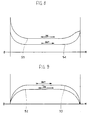
- the crane tip in the unit crane has two outermost positions, one as shown in Figure 1 and the other as shown in Figure 4. Between these two extreme positions the curves in Figure 8 have been taken up for forces operating on the crane tip, the curve 54 showing how the force varies from the inner position in Figure 1 to the outer position in Figure 4. Curve 55 also shows how the force varies during an inward movement. Curve 53 in Figure 9, finally, shows the speed of the crane tip from the situation according to Figure 1 to that according to Figure 4 and curve 52 shows the equivalent speed during an inward movement.
- the present invention has managed to produce a vehicle with a unit crane where, when not in use, the crane forms a convenient package, substantially horizontal, and is at a low level when the three arms are arranged one after the other, which is an advantage since the crane is then easy to service. It may then be suitable to bring the crane into the position shown in Figure 4. Another advantage is that the crane will on no account come into contact with the driver's cab 6. No special vehicle is necessary as previously to transport the unit crane, and crane and vehicle provide an advantageous unit through the use of a centrally controlled vehicle.
Landscapes
- Engineering & Computer Science (AREA)
- Mechanical Engineering (AREA)
- Jib Cranes (AREA)
Claims (15)
- Un système à trois bras dans lequel tous les bras peuvent être agencés l'un après l'autre et l'un au-dessus de l'autre, les deux bras d'extrémité (15, 18) étant rigides et le bras intermédiaire (14) étant de la nature d'un polygone, formé par un certain nombre d'unités de bras agencées en ligne l'une après l'autre, ces unités de bras étant jointes ensemble, et dans lesquelles deux points (28, 30) sur les unités de bras directement raccordées (17, 18, 19, 20) peuvent être menés à se déplacer l'un par rapport à l'autre,
caractérisé en ce que l'une des unités de bras (19a et 19b) entre ses extrémités a un bras tourné vers l'extérieur (19c) sur lequel l'un (28) desdits points (28 et 30) est situé et en que l'autre extrémité de ladite unité de bras (19a et 19b) est raccordée entre les extrémités d'une seconde unité de bras (20a et 20b), une partie (30a) de la seconde unité de bras (20a et 20b) étant ainsi incluse dans le polygone et l'autre partie (20b) constituant un bras tourné vers l'extérieur dont l'extrémité libre constitue le second (30) des deux points (28 et 30). - Un système à trois bras selon la revendication 1,
caractérisé en ce que le mouvement relatif entre les deux points (28 et 30) est obtenu au moyen d'un système hydraulique (38). - Un système à trois bras selon la revendication 1,
caractérisé en ce que le système est inclus dans une unité de grue et en ce que l'extrémité libre (26) du second bras (14) est de façon flexible raccordée à un bras support articulé (13), à son autre extrémité (34) de façon flexible raccordée à un support (7) pivotable sur une surface (35) de préférence la plate-forme (3) d'un véhicule, ladite surface étant de préférence inclinable. - Un système à trois bras selon la revendication 3,
caractérisé en ce que le bras support (13) est verticalement mobile par rapport au support (7). - Un système à trois bras selon la revendication 3,
caractérisé en ce que le second bras (14) et le bras support (13) sont verticalement mobile l'un par rapport à l'autre. - Un système à trois bras selon la revendication 3,
caractérisé en ce que tous les trois bras (13-15) peuvent être déplacés l'un au-dessus de l'autre et l'un après l'autre. - Un système à trois bras selon l'une des revendications ci-dessus,
caractérisé en ce que le support (7) est agencé sur une partie (3) d'un véhicule à commande centralisée (1), ladite partie étant équipée de la cabine du conducteur (6) du véhicule (1). - Un système à trois bras selon la revendication 7,
caractérisé en ce que ladite partie (3) est équipée de roues de bogie (5). - Un système à trois bras selon la revendication 7,
caractérisé en ce que la cabine du conducteur (6) peut être tournée en fonction du sens de marche. - Un système à trois bras selon la revendication 7,
caractérisé en ce que le moteur du véhicule (1) est agencé dans la seconde partie (2) du véhicule. - Un système à trois bras selon la revendication 3,
caractérisé en ce que la pointe extrême (16) de l'unité de grue a une courbe de vitesse (respectivement 52 ou 53) indiquant la valeur zéro aux positions extrêmes de la pointe (16) et entre ces positions étant de la nature d'un arc. - Un système à trois bras selon la revendication 3,
caractérisé en ce que la pointe (16) de l'unité de grue a sa plus grande force de traction à ses positions extrêmes et entre ces positions une valeur décroissante suivant une courbe ayant la forme d'un arc (respectivement 54 et 55). - Un système à trois bras selon l'une des revendications ci-dessus,
caractérisé en ce que les unités peuvent être accouplées l'une à l'autre sous la forme d'une gorge conique et d'un palier conique. - Un système à trois bras selon la revendication 3,
caractérisé en ce que la flexibilité entre les deux bras (13 et 20) est obtenue par l'extrémité de l'un des bras (19b) étant équipée de deux arbres (41 et 42) parallèles et opposés, chacun ayant un trou (43 et 44), lesdits trous (43 et 44) étant situés en regard l'un de l'autre et étant conçus pour recevoir une des extrémités d'un tourillon d'arbre (52) et par l'extrémité du second bras (13) étant de préférence formé comme un goujon (50) ayant deux surfaces planes opposées, la distance entre ces surfaces correspondant à la distance entre les arbres opposés (41 et 42) et où une ouverture (49) est agencée entre les deux surfaces, ladite ouverture (49) étant destinée à recevoir ledit tourillon d'arbre (52). - Un système à trois bras selon la revendication 14,
caractérisé en ce que chaque extrémité du tourillon d'arbre (52) est équipée d'une bague de serrage (45) située complètement ou partiellement dans l'un des trous (respectivement 43 ou 44) et dont la surface conique coopère avec la surface conique dans un cône de serrage (46) qui peut être vissé à chaque extrémité du tourillon d'arbre (52).
Applications Claiming Priority (1)
| Application Number | Priority Date | Filing Date | Title |
|---|---|---|---|
| PCT/SE1996/001186 WO1998012138A1 (fr) | 1996-09-23 | 1996-09-23 | Systeme a deux bras |
Publications (2)
| Publication Number | Publication Date |
|---|---|
| EP0927140A1 EP0927140A1 (fr) | 1999-07-07 |
| EP0927140B1 true EP0927140B1 (fr) | 2002-06-12 |
Family
ID=20401981
Family Applications (1)
| Application Number | Title | Priority Date | Filing Date |
|---|---|---|---|
| EP96937609A Expired - Lifetime EP0927140B1 (fr) | 1996-09-23 | 1996-09-23 | Systeme a deux bras |
Country Status (6)
| Country | Link |
|---|---|
| US (1) | US6193087B1 (fr) |
| EP (1) | EP0927140B1 (fr) |
| AU (1) | AU7510896A (fr) |
| CA (1) | CA2266530C (fr) |
| DE (1) | DE69621842T2 (fr) |
| WO (1) | WO1998012138A1 (fr) |
Families Citing this family (6)
| Publication number | Priority date | Publication date | Assignee | Title |
|---|---|---|---|---|
| SE521258C2 (sv) * | 1997-03-03 | 2003-10-14 | Motrac Ab | Tvåarmat system |
| FI116673B (fi) * | 2000-04-26 | 2006-01-31 | Loglift Oy Ab | Työkoneen puomisto |
| FI20055089A7 (fi) * | 2005-02-23 | 2006-08-24 | Ponsse Oyj | Liikeratanosturi |
| FI124684B (fi) * | 2012-12-03 | 2014-12-15 | Ponsse Oyj | Nosturi |
| CN107284326A (zh) * | 2017-06-11 | 2017-10-24 | 陇东学院 | 车载液压砖夹 |
| CN110588481A (zh) * | 2019-10-12 | 2019-12-20 | 八时物流科技(成都)有限公司 | 装卸货吊装臂、装卸货吊装装置及货车 |
Family Cites Families (9)
| Publication number | Priority date | Publication date | Assignee | Title |
|---|---|---|---|---|
| SE318382B (fr) | 1965-09-20 | 1969-12-08 | Hydrauliska Ind Ab | |
| DE7015853U (de) | 1970-01-31 | 1970-08-06 | Effer Sas | Mehrteiliger kranausleger. |
| US3828939A (en) * | 1973-06-06 | 1974-08-13 | J Tranchero | Three-stage self-propelled crane |
| SE383991B (sv) * | 1974-09-13 | 1976-04-12 | Motrac Gunnarson & Larsson Hb | Redskapsarm |
| DE2508872C3 (de) | 1975-02-28 | 1982-01-14 | Zakład Doswiadczalny Dzwigów Samochodowych i Samojezdnych, Bielsko-Biała | Fahrbarer Auslegerkran |
| IT1187983B (it) * | 1986-04-14 | 1987-12-23 | Jacques Tranchero | Gru autotrasportabile a braccio articolato comprendente tre stadi idraulici di sollevamento |
| SE454351B (sv) * | 1986-09-01 | 1988-04-25 | Osa Ab | Anordning for nivahallning av ett redskapsfeste till en vikarmskran |
| SE463668B (sv) * | 1989-05-16 | 1991-01-07 | Motrac Gunnarson & Larsson Hb | Kran |
| CA2045822A1 (fr) * | 1991-06-27 | 1992-12-28 | Sakari Pinomaki | Levage d'eperon |
-
1996
- 1996-09-23 EP EP96937609A patent/EP0927140B1/fr not_active Expired - Lifetime
- 1996-09-23 WO PCT/SE1996/001186 patent/WO1998012138A1/fr not_active Ceased
- 1996-09-23 US US09/269,162 patent/US6193087B1/en not_active Expired - Fee Related
- 1996-09-23 DE DE69621842T patent/DE69621842T2/de not_active Expired - Fee Related
- 1996-09-23 AU AU75108/96A patent/AU7510896A/en not_active Abandoned
- 1996-09-23 CA CA002266530A patent/CA2266530C/fr not_active Expired - Fee Related
Also Published As
| Publication number | Publication date |
|---|---|
| EP0927140A1 (fr) | 1999-07-07 |
| WO1998012138A1 (fr) | 1998-03-26 |
| DE69621842D1 (de) | 2002-07-18 |
| DE69621842T2 (de) | 2003-02-13 |
| CA2266530C (fr) | 2009-09-15 |
| AU7510896A (en) | 1998-04-14 |
| US6193087B1 (en) | 2001-02-27 |
| CA2266530A1 (fr) | 1998-03-26 |
Similar Documents
| Publication | Publication Date | Title |
|---|---|---|
| US8225947B2 (en) | Crane, in particular mobile crane with a narrow track and enlarged supporting base | |
| KR20160052389A (ko) | 작업 기계 | |
| WO1991014610A1 (fr) | Dispositif pour vehicules | |
| JPH06257182A (ja) | 前進機構または車輪駆動機構によって移動可能な作業機械 | |
| US4076128A (en) | Rotary crane | |
| CA2266530C (fr) | Systeme a deux bras | |
| KR100639721B1 (ko) | 자주식 작업 기계 | |
| KR20160052391A (ko) | 작업 기계용 하부 주행체 | |
| EP0945395B1 (fr) | Véhicule à flèche de levage, pouvant être utilisé comme une machine d' agriculture | |
| GB2159122A (en) | Movable counterweight arrangement, in particular for jib-type rotary cranes | |
| EP1025034B1 (fr) | Systeme a deux bras | |
| CS266342B2 (en) | Traffic vehicle with device for safety securing against overturn of load | |
| US4275902A (en) | Crane or excavator with auxiliary mechanism for transferring superstructure loads to the ground | |
| US6343799B1 (en) | Tilt mechanism for work machine | |
| EP0909668B1 (fr) | Structure pour supporter un cylindre à pression de fluide utilisé pour controller les oscillations d'un essieu de véhicule | |
| JP3993570B2 (ja) | クレーン用免震装置 | |
| US6557276B2 (en) | Earth-moving machine | |
| US12291434B2 (en) | Mobile crane | |
| FI106371B (fi) | Ohjaamohyttijärjestely | |
| JPH08510971A (ja) | 車両車輪用懸架装置 | |
| JP7783335B2 (ja) | デリックバラストを備えたクレーン | |
| WO1998002621A1 (fr) | Ensemble de chassis pour engin de construction | |
| EP3684721A1 (fr) | Chariot de grue | |
| EP0859888B1 (fr) | Ensemble chassis pour engin de construction articule | |
| JPH01235731A (ja) | 作業車両、殊にトラクターシャベル |
Legal Events
| Date | Code | Title | Description |
|---|---|---|---|
| PUAI | Public reference made under article 153(3) epc to a published international application that has entered the european phase |
Free format text: ORIGINAL CODE: 0009012 |
|
| 17P | Request for examination filed |
Effective date: 19990329 |
|
| AK | Designated contracting states |
Kind code of ref document: A1 Designated state(s): DE FI FR GB SE |
|
| 17Q | First examination report despatched |
Effective date: 20001020 |
|
| GRAG | Despatch of communication of intention to grant |
Free format text: ORIGINAL CODE: EPIDOS AGRA |
|
| GRAG | Despatch of communication of intention to grant |
Free format text: ORIGINAL CODE: EPIDOS AGRA |
|
| GRAH | Despatch of communication of intention to grant a patent |
Free format text: ORIGINAL CODE: EPIDOS IGRA |
|
| GRAH | Despatch of communication of intention to grant a patent |
Free format text: ORIGINAL CODE: EPIDOS IGRA |
|
| GRAA | (expected) grant |
Free format text: ORIGINAL CODE: 0009210 |
|
| AK | Designated contracting states |
Kind code of ref document: B1 Designated state(s): DE FI FR GB SE |
|
| REG | Reference to a national code |
Ref country code: GB Ref legal event code: FG4D |
|
| REF | Corresponds to: |
Ref document number: 69621842 Country of ref document: DE Date of ref document: 20020718 |
|
| PGFP | Annual fee paid to national office [announced via postgrant information from national office to epo] |
Ref country code: GB Payment date: 20020918 Year of fee payment: 7 |
|
| ET | Fr: translation filed | ||
| PLBE | No opposition filed within time limit |
Free format text: ORIGINAL CODE: 0009261 |
|
| STAA | Information on the status of an ep patent application or granted ep patent |
Free format text: STATUS: NO OPPOSITION FILED WITHIN TIME LIMIT |
|
| 26N | No opposition filed |
Effective date: 20030313 |
|
| PG25 | Lapsed in a contracting state [announced via postgrant information from national office to epo] |
Ref country code: GB Free format text: LAPSE BECAUSE OF NON-PAYMENT OF DUE FEES Effective date: 20030923 |
|
| GBPC | Gb: european patent ceased through non-payment of renewal fee |
Effective date: 20030923 |
|
| PGFP | Annual fee paid to national office [announced via postgrant information from national office to epo] |
Ref country code: DE Payment date: 20070329 Year of fee payment: 11 |
|
| PGFP | Annual fee paid to national office [announced via postgrant information from national office to epo] |
Ref country code: FR Payment date: 20070330 Year of fee payment: 11 |
|
| PG25 | Lapsed in a contracting state [announced via postgrant information from national office to epo] |
Ref country code: DE Free format text: LAPSE BECAUSE OF NON-PAYMENT OF DUE FEES Effective date: 20080401 |
|
| REG | Reference to a national code |
Ref country code: FR Ref legal event code: ST Effective date: 20080531 |
|
| PG25 | Lapsed in a contracting state [announced via postgrant information from national office to epo] |
Ref country code: FR Free format text: LAPSE BECAUSE OF NON-PAYMENT OF DUE FEES Effective date: 20071001 |
|
| PGFP | Annual fee paid to national office [announced via postgrant information from national office to epo] |
Ref country code: FI Payment date: 20090930 Year of fee payment: 14 |
|
| PGFP | Annual fee paid to national office [announced via postgrant information from national office to epo] |
Ref country code: SE Payment date: 20090930 Year of fee payment: 14 |
|
| REG | Reference to a national code |
Ref country code: SE Ref legal event code: EUG |
|
| PG25 | Lapsed in a contracting state [announced via postgrant information from national office to epo] |
Ref country code: FI Free format text: LAPSE BECAUSE OF NON-PAYMENT OF DUE FEES Effective date: 20100923 |
|
| PG25 | Lapsed in a contracting state [announced via postgrant information from national office to epo] |
Ref country code: SE Free format text: LAPSE BECAUSE OF NON-PAYMENT OF DUE FEES Effective date: 20100924 |