EP0927579A2 - Procédé et dispositif pour extraire des solides d' un mélange solide- liquide - Google Patents
Procédé et dispositif pour extraire des solides d' un mélange solide- liquide Download PDFInfo
- Publication number
- EP0927579A2 EP0927579A2 EP98123494A EP98123494A EP0927579A2 EP 0927579 A2 EP0927579 A2 EP 0927579A2 EP 98123494 A EP98123494 A EP 98123494A EP 98123494 A EP98123494 A EP 98123494A EP 0927579 A2 EP0927579 A2 EP 0927579A2
- Authority
- EP
- European Patent Office
- Prior art keywords
- solids
- conveyor
- discharge
- spiral
- vibration
- Prior art date
- Legal status (The legal status is an assumption and is not a legal conclusion. Google has not performed a legal analysis and makes no representation as to the accuracy of the status listed.)
- Withdrawn
Links
Images

Classifications
-
- B—PERFORMING OPERATIONS; TRANSPORTING
- B01—PHYSICAL OR CHEMICAL PROCESSES OR APPARATUS IN GENERAL
- B01D—SEPARATION
- B01D21/00—Separation of suspended solid particles from liquids by sedimentation
- B01D21/28—Mechanical auxiliary equipment for acceleration of sedimentation, e.g. by vibrators or the like
- B01D21/283—Settling tanks provided with vibrators
-
- B—PERFORMING OPERATIONS; TRANSPORTING
- B01—PHYSICAL OR CHEMICAL PROCESSES OR APPARATUS IN GENERAL
- B01D—SEPARATION
- B01D21/00—Separation of suspended solid particles from liquids by sedimentation
- B01D21/0027—Floating sedimentation devices
-
- B—PERFORMING OPERATIONS; TRANSPORTING
- B01—PHYSICAL OR CHEMICAL PROCESSES OR APPARATUS IN GENERAL
- B01D—SEPARATION
- B01D21/00—Separation of suspended solid particles from liquids by sedimentation
- B01D21/02—Settling tanks with single outlets for the separated liquid
-
- B—PERFORMING OPERATIONS; TRANSPORTING
- B01—PHYSICAL OR CHEMICAL PROCESSES OR APPARATUS IN GENERAL
- B01D—SEPARATION
- B01D21/00—Separation of suspended solid particles from liquids by sedimentation
- B01D21/24—Feed or discharge mechanisms for settling tanks
- B01D21/245—Discharge mechanisms for the sediments
- B01D21/2461—Positive-displacement pumps; Screw feeders; Trough conveyors
-
- B—PERFORMING OPERATIONS; TRANSPORTING
- B01—PHYSICAL OR CHEMICAL PROCESSES OR APPARATUS IN GENERAL
- B01J—CHEMICAL OR PHYSICAL PROCESSES, e.g. CATALYSIS OR COLLOID CHEMISTRY; THEIR RELEVANT APPARATUS
- B01J4/00—Feed or outlet devices; Feed or outlet control devices
- B01J4/001—Feed or outlet devices as such, e.g. feeding tubes
-
- B—PERFORMING OPERATIONS; TRANSPORTING
- B01—PHYSICAL OR CHEMICAL PROCESSES OR APPARATUS IN GENERAL
- B01D—SEPARATION
- B01D21/00—Separation of suspended solid particles from liquids by sedimentation
- B01D21/24—Feed or discharge mechanisms for settling tanks
- B01D21/2405—Feed mechanisms for settling tanks
- B01D21/2416—Liquid distributors with a plurality of feed points
Definitions
- the invention relates to a device for discharge of solids from a solid-liquid mixture according to the preamble of claim 1 and a method of discharging solids a solid-liquid mixture according to the preamble of claim 27.
- a device proposed that mentioned in claim 1 Features includes.
- This device stands out characterized in that a catch basin, which the Absorption of the solid-liquid mixture is used comprises at least one wall area, which with the help a vibration device arranged outside the collecting basin is vibratable.
- a vibration device arranged outside the collecting basin is vibratable.
- the vibrating device arranged outside the catch basin is because on the one hand it contaminates the Vibration facility through the wastewater respectively the solid-liquid mixture avoided, and because on the other hand the settling process within of the catch basin is not impaired becomes.
- An embodiment is particularly preferred the device, which is characterized in that several spread over the length of the catch basin arranged wall areas are provided with the vibration device interact.
- This embodiment can vibrate vibrations in several places in the catch basin initiate so that the settling of the solids particularly is favored.
- An embodiment of the is also preferred Device, which is characterized in that the Density of the solid-liquid mixture with a corresponding device and that the Vibration device depending on the Density is controlled. That way it is possible to influence the settling process in a targeted manner.
- An embodiment of the device is therefore preferred because of an endless conveyor is provided with the detection device the density of the solid-liquid mixture is coupled so that the discharge of solids from the mixture depending on the density he follows. With this configuration, the device work very effectively without it a particularly high design effort would be required.
- An embodiment of the method is preferred, which is characterized in that the staging of the solids depends on their density. This means that the solids are discharged only when there is sufficient pre-compression has taken place, if it is carried out with a correspondingly high efficiency can take place.
- one embodiment of the method preferred which is characterized in that the discharge of the solids depending on the height of the pre-compacted solid layer.
- this leads to an effective Effect of the discharge device or of the endless conveyor used for discharge is.
- it can be achieved be that within the deposited solid layer quasi a cavity (tunnel) created within which the funding is offset with the Solids are particularly effective can.
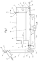
- the device 1 for discharging solids a solid-liquid mixture has a catch basin 3 on, in via an inlet 5, like indicated by a double arrow 7, the solid - Liquid mixture is introduced.
- the Collecting basin 3 is here as an example rectangular container 9 formed, which is exemplary here is closed on all sides and besides that Inlet 5 has an outlet 11 from how indicated by an arrow 13, that of solids at least largely released liquid can.
- the device 1 is with an endless conveyor 15 provided a horizontal conveyor 17 includes at least one conveyor spiral 19, only one of which is indicated here. she is driven by a drive device via a drive shaft 21, here from a motor 23, in rotation transferred.
- the conveyor spiral 19 extends over the entire length of the catch basin 3 and through a delivery pipe 25, which from the container 9 to one at an angle to the horizontal conveyor 17th running discharge conveyor 27 leads here is arranged vertically.
- This is part of the endless conveyor and has at least one discharge spiral 29 on the inside of a tubular Housing 31 arranged and via a drive shaft 33 from a drive device, here one Motor 35 is rotated.
- the discharge spiral promotes what is delivered by the funding spiral Material, i.e. from the solid-liquid mixture discharged solids from one first level N1 up to a higher level second level N2, so that this from an ejection opening 37, as indicated by a double arrow 39, can be delivered and for example in get a transport container.
- the endless conveyor 15 and its function are known in principle, so that not here to be dealt with. It will only still noted that the horizontal conveyor 17 connected pressure-tight to the discharge conveyor 27 is so that the discharged from the catch basin 3 Solids discharged from the mixture and ejected can be.
- the catch basin 3 or the container 9 have at least one wall area 41, here in total three wall areas 41, 43 and 45 on, respectively the via a vibration device 47 can be set in vibration.
- the wall areas 41 to 45 are here in the lower area the catch basin 3 and also in the area the delivery pipe 25 is provided.
- the vibration device 47 includes separate each wall area 41 to 45 assigned vibration units 49, 51 and 53, each a wall area 41, 43 and 45 are assigned.
- the wall areas are distributed over the length of the catch basin 3 and here arranged approximately at the level of the conveyor spiral 19.
- Dashed lines indicate that also in the area of the discharge conveyor 27 at least one vibration unit 55 can be provided.
- Figure 1 shows that the device 1 with a Control device 57 is provided via control lines 59, 61 and 63 with the vibration units 49, 51 and 53 is connected. It is also shown that the optional vibration unit 55 over a separate control line 65 with the control device 57 is connected.
- the device 1 is also with a device 67 for recording the density of the solid-liquid mixture or density the solids separated from the mixture.
- a device 67 for recording the density of the solid-liquid mixture or density the solids separated from the mixture.
- the Density of the deposited solids can, for example about the power consumption of the engine or about the speed of rotation of the impeller or the drive shaft can be detected.
- density measuring devices are known, so that their function is not discussed in detail here becomes. You just have to make sure that that Impeller not at such a speed is driven that the settling process is affected becomes. Incidentally, it is also conceivable use measuring sensors here, the density of capture settled solids.
- the device 67 via a Measuring line 75, which is indicated here by dashed lines, is connected to the control device 57.
- the solid-liquid mixture is over the Inlet 5 introduced into the catch basin 3, the means introduced into the interior of the container 9.
- the wall areas of the catch basin 3 respectively of the container 9 are designed to be elastic, that 47 vibrations via a vibration device in the catch basin 3 or in the mixture present there can be introduced. It is particularly advantageous that several distributed over the length of the catch basin Vibration units 49, 51 and 53 are provided are separately controllable via the control device 47 are.
- the control device 57 controls the vibration units via the associated control lines 59, 61 and 63 so that the solids settle out of the mixture.
- a solid line 79 is the maximum Level or the maximum height of the Solids in the catch basin 3 or Container 9 indicated. So if the solids deposited from the mixture so far that a desired sedimentation level has been reached this is determined via the device 67, for example in that the speed of the impeller 69 reduced or the power consumption of the motor 73 is increased.
- the device 1 is preferably operated or the procedure for discharging Solids carried out so that a pre-compression of the solids present in the mixture Dependence on the distance of the delivery pipe 25 takes place.
- the pre-compression takes place over the entire Length of the catch basin 3 to the solids particularly to separate effectively from the mixture.
- the intensity of the pre-compression is targeted by the Activation of the vibration units 49, 51 and 53 selected with the aid of the control device 57, that the eligibility of the mix precipitated solids are not affected early becomes. It is therefore ensured that for example, the solids do not multiply near the motor 23 of the horizontal conveyor 17 deposit and hinder the conveyor spiral 19 or block even.
- the vibration unit 49 In the case of a control cycle first the vibration unit 49, then the vibration unit 51 and finally that of the discharge spiral 29 most distant vibration unit 53 controlled.
- the activation and break times are depending on the density or chosen according to a predefinable schedule.
- the vibration units can also (at times) in parallel, so be activated at the same time.
- the intensity The vibration can be caused by the duty cycle but also due to different imbalances and / or masses of the Vabrationsaku changed become.
- the control of the vibration units 49, 51 and 53 is preferably carried out via the control device 57 so that the solids in the range Deposit horizontal conveyor 17 so that it is quasi there is a tunnel in the separated solid area, within which the conveyor spiral 19 rotates is displaced and that located in the spiral passage Material or the solids this tunnel will be carried out so that this over the conveyor tube 25 reach the discharge conveyor 27.
- the solids can then be removed from the discharge spiral 29 still be promoted up and out of the discharge opening 27 fall.
- the Control device 57 one or more vibration units 49, 51 and 53 for a predetermined one Period in progress. After reaching a defined The degree of density of the deposited solids becomes Endless conveyor 19 activated. This means The conveyor spiral is via motors 23 and 35 19 and the discharge spiral 29 set in rotation, to remove settled solids from the mixture.
- the switch-off time is also for the one that acts as a discharge system Endless conveyor 15 determined, for example based on the height of the deposited solid layer or the one given in this layer Density.
- the vibration units are purely time-controlled operate, that is the vibration time of the various To choose different vibration units, and thereby on the detection of the height and / or To dispense with the density of the deposited solid layer.
- a further compression can, as indicated in the figure, through the additional vibration unit 55 take place in the discharge conveyor 27.
- the endless conveyor 15 a reverse flow from the discharge conveyor 27 into the conveyor pipe 25 or in the area of the horizontal conveyor 17 to avoid.
- the vibrating device 47 serves to deposit the Solids from the solid-liquid mixture to promote and adjust so that a high Effectiveness in removing solids from the Mixture results. It is clear that the catch basin 3 only individual vibrating wall areas needs to show. However, it is also possible the catch basin 3 or the container 9 so to train, for example with metal walls provided that these can basically vibrate anywhere but are only vibrating in the areas which vibration units are provided.
- An essential feature of the device 1 is that the vibration units of the vibration device outside the catch basin 3 or Container 9 are arranged and with the solid-liquid mixture do not come into contact. Thereby there is a very high level of functional reliability the vibration units.
- the container On the other hand, find themselves inside the discharge basin respectively the container has no protruding elements on the one hand impair the weaning process and on the other hand, the discharge of the solids from the Mixture could hinder. It also shows that service and repair work on the vibration units are particularly easy to carry out. Finally, it also emerges that existing devices with such a vibration device can be easily and inexpensively retrofitted can.
- FIG. 2 shows a device 10 for discharging Solids from a solid-liquid mixture with a catch basin 30 that a round Containers 90 has.
- Such devices are also known as round sand fishing.
- the device 10 is with an endless conveyor 150 equipped from the solid-liquid mixture precipitated solids from one first level N1 to a higher second Level N2 promoted. It includes a horizontal conveyor 170 with a conveyor spiral 190, the via a drive shaft 210 from a drive device, here from a motor 230, in rotation is transferred. On their opposite the engine The end of the conveyor spiral 190 is a discharge conveyor 270 of the endless conveyor device 150 is provided, which is also designed as a spiral conveyor and a discharge spiral 290.
- Spirals can also be designed as snails be.
- the discharge conveyor 270 has an ejection opening 370 provided, over which, as by a double arrow 390 indicated, discharged from the mixture Solids can be released.
- the device 10 comprises an agitator 75 with a drive motor 77, which is a drive shaft 79 set in rotation. At this is at least one arm, here several arms 81 are provided, on top of each other in different levels the drive shaft 79 are rotatably attached.
- the Device 10 is with a loosening device 83 equipped here, the loosening spiral 85, which also here for simplification the construction via the drive shaft 79 can be set in rotation by the drive motor 77 is.
- the device 10 is with a vibration device 470 provided, which is a vibration unit 49 comprises, which is attached to the outside of the container 90. It is also conceivable to have several such vibration units outside of the container 90 but also in the area of the horizontal conveyor 170 and the discharge conveyor 270 to be provided.
- the solid-liquid mixture becomes like this is known tangentially in such devices introduced into the upper region of the container 90, so that a rotating rotational flow arises.
- the solids sink inside the container 90, while that of the solids in essential completely freed liquid over derived an outlet 110 only indicated here becomes.
- the container 90 is cylindrical at the top educated. On the upper cylindrical part includes a conical that narrows downwards Range. In the upper part of this area, on an imaginary one, shown here in dashed lines Level E1 is a first ventilation unit 87 a ventilation device is provided. On the same Level is here on the opposite side of the container 90, a second ventilation unit 89 intended. It is also possible at this level E1 to provide a circumferential ventilation pipe.
- the ventilation units 87 and 89 trained as so-called ventilation candles have exposed pipe sections which comprise a gas-permeable wall. This can be achieved by perforating the wall be, but also in that the tube or sections of this tube made of porous Ceramics exist.
- a ventilation unit can also include more than one ventilation candle. Conceivable it is also arranged in the area of plane E1 use all-round ventilation pipe.
- the conically tapering area of the Container 90 sits in a cylindrical or preferably conically widening area continues, which is connected to the horizontal conveyor 170 is.
- the conical expansion of this area prevented clogging of the device 10.
- FIG. 2 shows that the vibrating device 470 or their vibration unit 490 preferably arranged in the lowest region of the container 90 is, namely in the conically widening Area here just below the end of the tapered area of the Container 90.
- Figure 2 also shows that the arms 81 of the Agitator 75 in the lower area of the conical tapered portion of the container 90 is arranged are.
- the ventilation device with the ventilation units 87 to 93 is with an air respectively Gas guide device provided to the ventilation units 87 to 93 associated baffles.
- the Baffles 97 and 99 of the upper ventilation units 87 and 89 have one on the inner wall of the container fixed, horizontal baffle section to which there is an upstanding sheet metal section connecting at an angle to that horizontal baffle section runs. In which Embodiment shown here run the sheet metal sections obliquely inwards to the central axis of the container 90 or the drive shaft 79. They are directed upwards and prevent the ventilation units 87 and 89 escaping air turbulence in the initiate settling solids so that the settling process through these ventilation units 87 and 89 is not disturbed.
- the ventilation units serve to top organic contaminants to carry out, so that this together with the water emerge from outlet 110.
- the gas guide device 95 also has guide plates 101 and 103 on the lower ventilation units 91 and 93 are assigned and in turn essentially horizontal baffle sections exhibit at an angle Connect the running sheet metal sections. These are down here.
- the baffles 101 and 103 thus protect the ventilation units 91 and 93 before the solids sinking from above. she but also shield the ventilation units 91 and 93 from, so that air escaping here is not easy in the tapering downwards Can reach the area of the container 90, in which a laminar flow from top to bottom the settling solids exist.
- the gas guiding device not only to include baffles made of metal needs. It can also be non-metallic materials be used.
- the solids sink conically downwards tapered area, with a laminar Flow is formed.
- the baffle 97 the first ventilation unit 87 and the baffle 99 of the second ventilation unit 89 is prevented that the air flowing up the laminar Flow and the settling process impaired.
- the settling process is carried out by the vibration device 47 or its vibration unit 49 promoted the vibrations in the solid-liquid mixture initiates in the container 90.
- the condense Solids Below of the conically tapering area of the container 90, which is also used as a sedimentation chamber can be called, the condense Solids.
- the density of the deposited solids is detected by the agitator 75, namely by the resistance that the arms 81 pass through experience the sedimentation zone.
- the density can thereby based on the current consumption of the motor 77 or based on its speed can be determined reduced with increasing density. It is conceivable also to provide a measuring probe instead of the arms. It is essential that the density in the sedimentation space is detected.
- the way plays for the function of the device 10 is at most a subordinate one Meaning.
- Ventilation units 91 and 93 which are So in the transition area between which is conical tapered and flared downwards Area of the container 90 are only temporarily activated.
- the gases escaping here respectively the air serves organic components from the layer of settling solids to carry out.
- the lower ventilation units 91 and 93 are therefore only activated temporarily, the laminar flow of the settling solids not to be disturbed in the sedimentation room.
- the air emerging here combines with the organic Components and serves as their means of transport.
- the spiral 85 of the loosening device 83, the in the conically widening area the container 90 is arranged, serves the loosening and thus the mechanical cleaning of the here deposited solids that further down sink to the endless conveyor 150.
- a control device 570 can be provided the, as described with reference to Figure 1, with the vibrating device 470 cooperates and Control lines 571 has. By the way, it is possible, the control device 570 for control the ventilation units 87 to 93 and and finally, the horizontal conveyor 170 and the discharge conveyor 270 of the endless conveyor 150 to control.
- the upper one is preferably provided Ventilation units 87 and 89 practically continuously to apply a gas or air, while the lower ventilation units 91 and 93 only for a short time with air respectively Gas are applied so that the laminar flow in the sedimentation room not disturbed becomes.
- Vibration units can also be used in the device 10 in the area of horizontal respectively Discharge conveyor are provided by the further compression of the solids in the area of Endless conveyor 150 and serve by the Control device 570 can be controlled. It is independent control of the vibration units also conceivable regardless of the vibration unit 490 described above.
- the device 10 a pre-compression of those present in the mixture Solids is possible. Especially with mixtures with a low consistency due to this pre-compression the discharge of the solids at all from the mixture. At the same time is due to the compression in the collecting basin 30 or in the container 90 a stuffing or Grafting effect that prevents that liquid from the catch basin 30 in the discharge conveyor 270 arrives.
- This darning respectively Grafting effect can be caused by vibration units in the area of horizontal respectively of the discharge conveyor. These vibration units can also be designed be and be controlled, like that in the figure 1 illustrated embodiment has been.
- Discharge conveyor in the middle of the catch basin shown in FIG Discharge conveyor is arranged, for example corresponds to the discharge conveyor 270.
- the deposed Solids could thus come directly from the discharge basin be carried out. Then he would have to modified agitator can be used.
- the vibration device 470 not only the compression the sinking solids serves, but also helps keep the solids in vibration are shifted so that organic buildup be rubbed off and removed.
- the discharge of these organic substances is both by the Loosening device 83 or its Spiral 85 as well as through the ventilation device promoted with ventilation units 87 to 93.
Landscapes
- Chemical & Material Sciences (AREA)
- Chemical Kinetics & Catalysis (AREA)
- Organic Chemistry (AREA)
- Filtration Of Liquid (AREA)
- Separation Of Solids By Using Liquids Or Pneumatic Power (AREA)
Applications Claiming Priority (2)
| Application Number | Priority Date | Filing Date | Title |
|---|---|---|---|
| DE19758038A DE19758038A1 (de) | 1997-12-29 | 1997-12-29 | Vorrichtung und Verfahren zum Austragen von Feststoffen aus einem Feststoff-Flüssigkeits-Gemisch |
| DE19758038 | 1997-12-29 |
Publications (2)
| Publication Number | Publication Date |
|---|---|
| EP0927579A2 true EP0927579A2 (fr) | 1999-07-07 |
| EP0927579A3 EP0927579A3 (fr) | 2002-02-06 |
Family
ID=7853477
Family Applications (1)
| Application Number | Title | Priority Date | Filing Date |
|---|---|---|---|
| EP98123494A Withdrawn EP0927579A3 (fr) | 1997-12-29 | 1998-12-14 | Procédé et dispositif pour extraire des solides d' un mélange solide- liquide |
Country Status (2)
| Country | Link |
|---|---|
| EP (1) | EP0927579A3 (fr) |
| DE (1) | DE19758038A1 (fr) |
Cited By (3)
| Publication number | Priority date | Publication date | Assignee | Title |
|---|---|---|---|---|
| WO2003101582A1 (fr) * | 2002-05-31 | 2003-12-11 | Farmatic Biotech Energy Ag | Dispositif et procede de separation de solides dans des liquides |
| CZ307198B6 (cs) * | 2016-10-13 | 2018-03-14 | Envi-Pur S.R.O. | Dosazovák pro zahušťování aktivovaného kalu při čištění odpadních vod |
| US11931677B2 (en) | 2020-01-31 | 2024-03-19 | Hydra Water Ab | Separation device and method to separate contaminants from contaminated water |
Families Citing this family (7)
| Publication number | Priority date | Publication date | Assignee | Title |
|---|---|---|---|---|
| DE19923209A1 (de) * | 1999-05-20 | 2000-11-23 | Grieshaber Gmbh & Co Kg Geb | Vorrichtung und Verfahren zum trennscharfen Austrag fester und flüssiger Stoffe unterschiedlicher Wichte aus Trennungsanlagen, die eines Fluides bedürfen, zur Trennung von Stoffen nach deren Wichte |
| DE102004058421A1 (de) * | 2004-10-01 | 2006-04-13 | Hans Huber Ag Maschinen- Und Anlagenbau | Anlage zur mechanischen Reinigung von Flüssigkeiten und Verfahren zur Abscheidung von Sinkstoffen |
| US20070075024A1 (en) * | 2005-10-04 | 2007-04-05 | Campbell Brian W | Advanced gravity sedimentation system and method |
| GB0600487D0 (en) * | 2006-01-11 | 2006-02-22 | Earth Tech Engineering Ltd | Method and apparatus of sludge treatment |
| CN108262150A (zh) * | 2018-01-03 | 2018-07-10 | 茂名市茂南嘉泥科技发展有限公司 | 一种土粒粒径分离设备 |
| CN110448940B (zh) * | 2018-05-07 | 2024-01-23 | 浙江联池水务设备股份有限公司 | 一种净水厂排泥水处理系统及处理方法 |
| CN111468039A (zh) * | 2020-04-15 | 2020-07-31 | 湖北民生生物医药有限公司 | 一种用于环氧孕酮生产用的高稳定性上料装置 |
Family Cites Families (7)
| Publication number | Priority date | Publication date | Assignee | Title |
|---|---|---|---|---|
| US2973866A (en) * | 1959-05-14 | 1961-03-07 | Albert L Genter | Settling tank |
| US3628667A (en) * | 1969-09-23 | 1971-12-21 | Buckau Wolf Maschf R | Decantation apparatus |
| US4165283A (en) * | 1976-10-28 | 1979-08-21 | Industrial Pollution Control Corp. | Multi-stage purification system |
| DE2925797C2 (de) * | 1979-06-26 | 1983-07-21 | Szilikátipari Központi Kutató és Tervezö Intézet, 1034 Budapest | Vibrations-Entwässerungseinrichtung für körniges Material |
| JPH0712556B2 (ja) * | 1992-08-18 | 1995-02-15 | ナカヤ実業株式会社 | 泥水処理装置 |
| NL9301599A (nl) * | 1993-09-15 | 1995-04-03 | Jan Willem Van De Graaf | Waterrecycling-systeem op de tegenstroomplaten separator met met continue slib verwijdering d.m.v. eindloze schijvenketting. |
| DE4415858A1 (de) * | 1994-05-05 | 1995-11-09 | Bormet Horst | Verfahren und Vorrichtung zur Sedimentabscheidung aus Abwasser |
-
1997
- 1997-12-29 DE DE19758038A patent/DE19758038A1/de not_active Withdrawn
-
1998
- 1998-12-14 EP EP98123494A patent/EP0927579A3/fr not_active Withdrawn
Cited By (3)
| Publication number | Priority date | Publication date | Assignee | Title |
|---|---|---|---|---|
| WO2003101582A1 (fr) * | 2002-05-31 | 2003-12-11 | Farmatic Biotech Energy Ag | Dispositif et procede de separation de solides dans des liquides |
| CZ307198B6 (cs) * | 2016-10-13 | 2018-03-14 | Envi-Pur S.R.O. | Dosazovák pro zahušťování aktivovaného kalu při čištění odpadních vod |
| US11931677B2 (en) | 2020-01-31 | 2024-03-19 | Hydra Water Ab | Separation device and method to separate contaminants from contaminated water |
Also Published As
| Publication number | Publication date |
|---|---|
| EP0927579A3 (fr) | 2002-02-06 |
| DE19758038A1 (de) | 1999-07-01 |
Similar Documents
| Publication | Publication Date | Title |
|---|---|---|
| EP0908569B1 (fr) | Dispositif de tamisage pour eaux usées dans une canalisation | |
| EP0040425B1 (fr) | Dispositif pour évacuer des matériaux flottants et débris d'un égout, notamment d'une installation d'épuration | |
| WO2004087289A1 (fr) | Dispositif permettant de retirer un produit de filtrage d'un liquide | |
| DE4143376C2 (de) | Kompaktanlage zum Abscheiden und Entfernen von Rechengut und Sand aus Zulaufgerinnen | |
| DE19907067C2 (de) | Trennvorrichtung für das Aussondern von Feststoffen aus einem Flüssigkeits-Feststoff-Gemisch | |
| DE2042353C3 (de) | Vorrichtung zum Filtrieren von Flüssigkeiten | |
| DE3122131C2 (de) | Vorrichtung zur Entnahme und Entwässerung von Feststoffen aus Flüssigkeiten, insbesondere aus Gerinnen von Kläranlagen | |
| EP0596052A1 (fr) | Procede et dispositif d'entree pour l'alimentation de dessableurs plats ou de bassins de decantation. | |
| EP0927579A2 (fr) | Procédé et dispositif pour extraire des solides d' un mélange solide- liquide | |
| EP1516672B1 (fr) | Procédé et dispositif pour la séparation de matière organique de matière inorganique | |
| DE2813056A1 (de) | Trennvorrichtung zum wiedergewinnen der zuschlagstoffe aus nicht-abgebundenem beton | |
| DE19501034A1 (de) | Vorrichtung zum Abtrennen von Schwimmstoffen und Sinkstoffen aus einer Flüssigkeit | |
| EP1194383A1 (fr) | Dispositif de deshydratation des boues | |
| WO2000040320A1 (fr) | Dispositif de separation pour fluides | |
| DE10200599B4 (de) | Vorrichtung zum Abscheiden von organischem und anorganischem Material aus einer Flüssigkeit | |
| DE19533935C2 (de) | Vorrichtung für die Reinigung von Abwasser | |
| DE4415858A1 (de) | Verfahren und Vorrichtung zur Sedimentabscheidung aus Abwasser | |
| DE102005002997A1 (de) | Schneckenfilterpresse | |
| DE29620825U1 (de) | Vorrichtung zum Separieren und Reinigen eines Schweb-, Sinkstoff-Abwasser-Gemisches | |
| EP1927388A1 (fr) | Système de filtre de réservoir des eaux pluviales | |
| DE4429537C2 (de) | Abwasserreinigungsanlage | |
| DE10224172B4 (de) | Vorrichtung und Verfahren zur Trennung von Feststoffen aus Flüssigkeiten bzw. zur Reinigung von Flüssigkeiten oder Festflüssiggemischen | |
| WO1995019212A1 (fr) | Dispositif de nettoyage de solides contenus dans des eaux residuaires | |
| DE20018715U1 (de) | Sandfanganlage | |
| DE2832277C2 (fr) |
Legal Events
| Date | Code | Title | Description |
|---|---|---|---|
| PUAI | Public reference made under article 153(3) epc to a published international application that has entered the european phase |
Free format text: ORIGINAL CODE: 0009012 |
|
| AK | Designated contracting states |
Kind code of ref document: A2 Designated state(s): AT BE CH CY DE DK ES FI FR GB GR IE IT LI LU MC NL PT SE |
|
| AX | Request for extension of the european patent |
Free format text: AL;LT;LV;MK;RO;SI |
|
| PUAL | Search report despatched |
Free format text: ORIGINAL CODE: 0009013 |
|
| AK | Designated contracting states |
Kind code of ref document: A3 Designated state(s): AT BE CH CY DE DK ES FI FR GB GR IE IT LI LU MC NL PT SE |
|
| AX | Request for extension of the european patent |
Free format text: AL;LT;LV;MK;RO;SI |
|
| STAA | Information on the status of an ep patent application or granted ep patent |
Free format text: STATUS: THE APPLICATION IS DEEMED TO BE WITHDRAWN |
|
| 18D | Application deemed to be withdrawn |
Effective date: 20010901 |