EP0927671B1 - Système et procédé pour commander le freinage d'une roue de véhicule - Google Patents
Système et procédé pour commander le freinage d'une roue de véhicule Download PDFInfo
- Publication number
- EP0927671B1 EP0927671B1 EP98310646A EP98310646A EP0927671B1 EP 0927671 B1 EP0927671 B1 EP 0927671B1 EP 98310646 A EP98310646 A EP 98310646A EP 98310646 A EP98310646 A EP 98310646A EP 0927671 B1 EP0927671 B1 EP 0927671B1
- Authority
- EP
- European Patent Office
- Prior art keywords
- torque
- brake
- controller
- brake torque
- wheel
- Prior art date
- Legal status (The legal status is an assumption and is not a legal conclusion. Google has not performed a legal analysis and makes no representation as to the accuracy of the status listed.)
- Expired - Lifetime
Links
- 238000000034 method Methods 0.000 title claims description 10
- 230000007704 transition Effects 0.000 claims description 21
- 239000012530 fluid Substances 0.000 claims description 2
- 238000001514 detection method Methods 0.000 claims 3
- 238000013459 approach Methods 0.000 description 8
- 239000000463 material Substances 0.000 description 6
- 230000007423 decrease Effects 0.000 description 4
- 230000001133 acceleration Effects 0.000 description 3
- 230000008859 change Effects 0.000 description 3
- 238000010586 diagram Methods 0.000 description 3
- 230000000694 effects Effects 0.000 description 3
- 230000003213 activating effect Effects 0.000 description 2
- 238000012986 modification Methods 0.000 description 2
- 230000004048 modification Effects 0.000 description 2
- OKTJSMMVPCPJKN-UHFFFAOYSA-N Carbon Chemical compound [C] OKTJSMMVPCPJKN-UHFFFAOYSA-N 0.000 description 1
- 230000009471 action Effects 0.000 description 1
- 229910052799 carbon Inorganic materials 0.000 description 1
- 239000013068 control sample Substances 0.000 description 1
- 230000007246 mechanism Effects 0.000 description 1
- 230000000704 physical effect Effects 0.000 description 1
- 238000003825 pressing Methods 0.000 description 1
- 239000000523 sample Substances 0.000 description 1
Images




Classifications
-
- B—PERFORMING OPERATIONS; TRANSPORTING
- B60—VEHICLES IN GENERAL
- B60T—VEHICLE BRAKE CONTROL SYSTEMS OR PARTS THEREOF; BRAKE CONTROL SYSTEMS OR PARTS THEREOF, IN GENERAL; ARRANGEMENT OF BRAKING ELEMENTS ON VEHICLES IN GENERAL; PORTABLE DEVICES FOR PREVENTING UNWANTED MOVEMENT OF VEHICLES; VEHICLE MODIFICATIONS TO FACILITATE COOLING OF BRAKES
- B60T8/00—Arrangements for adjusting wheel-braking force to meet varying vehicular or ground-surface conditions, e.g. limiting or varying distribution of braking force
- B60T8/32—Arrangements for adjusting wheel-braking force to meet varying vehicular or ground-surface conditions, e.g. limiting or varying distribution of braking force responsive to a speed condition, e.g. acceleration or deceleration
- B60T8/321—Arrangements for adjusting wheel-braking force to meet varying vehicular or ground-surface conditions, e.g. limiting or varying distribution of braking force responsive to a speed condition, e.g. acceleration or deceleration deceleration
- B60T8/325—Systems specially adapted for aircraft
-
- B—PERFORMING OPERATIONS; TRANSPORTING
- B60—VEHICLES IN GENERAL
- B60T—VEHICLE BRAKE CONTROL SYSTEMS OR PARTS THEREOF; BRAKE CONTROL SYSTEMS OR PARTS THEREOF, IN GENERAL; ARRANGEMENT OF BRAKING ELEMENTS ON VEHICLES IN GENERAL; PORTABLE DEVICES FOR PREVENTING UNWANTED MOVEMENT OF VEHICLES; VEHICLE MODIFICATIONS TO FACILITATE COOLING OF BRAKES
- B60T8/00—Arrangements for adjusting wheel-braking force to meet varying vehicular or ground-surface conditions, e.g. limiting or varying distribution of braking force
- B60T8/17—Using electrical or electronic regulation means to control braking
- B60T8/176—Brake regulation specially adapted to prevent excessive wheel slip during vehicle deceleration, e.g. ABS
- B60T8/1761—Brake regulation specially adapted to prevent excessive wheel slip during vehicle deceleration, e.g. ABS responsive to wheel or brake dynamics, e.g. wheel slip, wheel acceleration or rate of change of brake fluid pressure
- B60T8/17616—Microprocessor-based systems
-
- B—PERFORMING OPERATIONS; TRANSPORTING
- B60—VEHICLES IN GENERAL
- B60T—VEHICLE BRAKE CONTROL SYSTEMS OR PARTS THEREOF; BRAKE CONTROL SYSTEMS OR PARTS THEREOF, IN GENERAL; ARRANGEMENT OF BRAKING ELEMENTS ON VEHICLES IN GENERAL; PORTABLE DEVICES FOR PREVENTING UNWANTED MOVEMENT OF VEHICLES; VEHICLE MODIFICATIONS TO FACILITATE COOLING OF BRAKES
- B60T8/00—Arrangements for adjusting wheel-braking force to meet varying vehicular or ground-surface conditions, e.g. limiting or varying distribution of braking force
- B60T8/32—Arrangements for adjusting wheel-braking force to meet varying vehicular or ground-surface conditions, e.g. limiting or varying distribution of braking force responsive to a speed condition, e.g. acceleration or deceleration
- B60T8/52—Torque sensing, i.e. wherein the braking action is controlled by forces producing or tending to produce a twisting or rotating motion on a braked rotating member
Definitions
- the present invention relates generally to brake systems for vehicles, and more particularly to a brake control system based on torque feedback control.
- Brake systems for vehicles are well known in the art.
- Most brake systems include a brake actuator for exerting pressure on brake material.
- the brake material in turn exerts a braking torque on the element to be braked (e.g., the wheel of the vehicle).
- the brake actuator may be hydraulic or electromechanical, for example. By selectively activating the brake actuator, a desired amount of braking torque, or force, may be applied to the element to be braked.
- brake systems for vehicles have included a controller which utilizes the measured braking torque applied to the wheel to compensate for brake fade (due to thermal effects) and grabby brakes (common with carbon brakes).
- a torque sensor would measure the torque applied to the wheel and the output of the torque sensor was fed back to the controller.
- P-I controllers are used in combination with the low speed cutout. If braking is applied at high speed, the integral portion of the P-I controller will tend to overshoot and cause the brake to grab initially. This can cause a short wheel skid if the surface on which the wheel is running is not dry.
- US-A-4 822 113 discloses a controller having all the features of the preamble of claim 1.
- a torque level transitioning controller for controlling a braking torque applied to a wheel of a vehicle via a brake actuator and assembly based on an output of a torque sensor which measures an amount of brake torque applied to the wheel, the output of the torque sensor being fed back to the torque level transitioning controller, the torque level transitioning controller comprising: an input for receiving a brake torque command indicative of a desired amount of brake torque to be applied to the wheel, and an output for providing a brake torque output command to the brake actuator and assembly which applies a brake torque to the wheel based on the brake torque output command; another input for receiving the output of the torque sensor; and circuitry for adjusting the brake torque output command provided to the brake actuator and assembly using torque feedback control based on the output received from the torque sensor, characterized in that the torque level transitioning controller is configured so as to limit a degree of the torque feedback control based on the measured amount of brake torque applied to the wheel.
- a system for controlling a braking torque applied to a wheel of a vehicle comprising: a controller according to the first aspect of the invention; and a torque sensor operatively coupled to the brake actuator and assembly and the torque level transitioning controller, for measuring an amount of brake torque applied to the wheel and feeding back a signal to the torque level transitioning controller indicative of the amount of applied brake torque.
- a method for controlling a braking torque applied to a wheel of a vehicle comprising the steps of: receiving a brake torque command indicative of a desired amount of brake torque to be applied to the wheel, and providing a brake torque output command to a brake actuator and assembly which applies a brake torque to the wheel based on the brake torque output command; measuring an amount of brake torque applied to the wheel and using a signal indicative of the amount of applied brake torque to perform torque feedback control of the brake torque output command; and adjusting the brake torque output command provided to the brake actuator using the torque feedback control based on the measured amount of brake torque, the adjusting step including a step of limiting a degree of the torque feedback control based on the amount of brake torque applied to the wheel.
- a brake system and torque feedback controller which utilizes low torque cutout rather than low speed cutout.
- the low torque cutout is further improved by gradually transitioning between torque feedback and open loop control over a range of torque.
- the controller of the present invention allows torque compensation operation to zero wheel speed, and avoids discontinuities in braking regardless of time or torque level. Also the controller can allow a brake to fill and engage the wheel before the full feedback signal is presented to the controller so as to eliminate the phenomena of grabby brakes.
- a brake control system with torque compensation for an aircraft in accordance with the present invention is generally designated 10.
- Brake control on an aircraft is usually structured in a paired wheel configuration for functional modularity. For example, if the aircraft has two wheels on the left side of the aircraft and two wheels on the right side, the outer two wheels form a pair and the inner two wheels form another pair. Within a pair there is a right wheel control and left wheel control. The left and right wheel control functions are uncoupled except for locked wheel protection.
- the basic unit therefore consists of control of a single wheel which can be left or right.
- wheel is intended to refer collectively to both the wheel and tire.
- the brake control system 10 as shown in Fig. 1 represents the basic unit for providing brake control of a single wheel (left or right).
- control for the other wheel(s) can be provided via corresponding systems 10 or in a single system incorporating the same inventive principles.
- the preferred embodiment of the present invention provides brake control in connection with an aircraft.
- the brake control system with torque compensation according to the present invention has utility for virtually any type of vehicle and is not limited necessarily to brake control for aircraft.
- the system 10 includes a pilot brake device 12 for providing operator brake control.
- the system 10 includes a torque level transitioning controller 14.
- the controller 14 controls the amount of torque applied by the braking system 10 as is described more fully below.
- the controller 14 provides a control signal to a brake actuator 16 included in the system 10.
- the brake actuator 16 may be any conventional type actuator (e.g., hydraulic, electromechanical, or pneumatic) for applying pressure to the brake material (not shown) in a brake assembly 18.
- the brake assembly 18 in turn provides braking action to a wheel 20 by exerting a braking torque on the wheel 20 as is conventional.
- the system 10 further includes a brake torque sensor 22 which measures the amount of torque exerted by the brake actuator 16 and brake assembly 18 on the wheel 20.
- the measured torque is input to the controller 14.
- the controller 14 uses torque compensation to control the amount of braking applied to the wheel 20.
- the present invention is not reliant on wheel speed. Rather, the present invention utilizes what is referred to as "low torque cutout" in which the controller 14 disabtes torque compensation based on low measured torque.
- the low torque cutout is further improved by the controller 14 gradually transitioning between torque feedback and open loop control over a range of torque as will be discussed.
- the pilot brake device 12 comprises a pedal or equivalent thereof.
- the pilot of the aircraft activates the pilot brake device 12 by pushing the pedal (or its equivalent).
- the depression of the pedal is converted to an electrical signal (brake torque command signal T c ) which is provided to the controller 14.
- the value of the command signal T c is indicative of the degree of depression of the pedal, and is related to the amount of brake torque requested by the pilot as is conventional.
- the controller 14 outputs a brake torque output command T output to the brake actuator 16 which is based on the value of the brake torque command T c . Responsive to the output command T output , the brake actuator 16 applies pressure to the brake material in the brake assembly 18. Such pressure results in a brake torque being applied to the wheel 20 in order to slow the speed of the wheel 20.
- the torque sensor 22 detects the amount of torque presently exerted on the wheel 20 and provides as an output a signal T m indicative of the measured amount of torque.
- the signal T m is fed back to the controller 14 as shown, and is used by the controller 14 to perform torque feedback control.
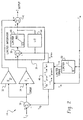
- Fig. 2 illustrates in detail a first embodiment of the torque controller 14.
- the controller 14 is used to control a hydraulic pressure valve (not shown) in the brake actuator 16.
- a hydraulic pressure valve not shown
- the pressure valve By controlling the pressure valve the amount of pressure applied by the brake actuator 16 to the brake material is controlled. Accordingly, the output T output of the controller 14 is provided to the pressure valve in the brake actuator 16 in order to control the braking torque.
- the command signal T c representing the desired amount of brake torque is input to a summer 30.
- the summer 30 compares the command signal T c to a torque feedback signal T fb which is provided to a negative input of the summer 30.
- the output of the summer 30 represents a torque error signal T error .
- the signal T error is input to a proportional gain amplifier 32 and to an integral gain amplifier 34 which are respectively included in the proportional and integral portions of a P-I controller as is known.
- the proportional gain amplifier 32 preferably has a preselected gain which is less than unity, and outputs a signal which is always proportional to the torque error signal T error .
- the integral gain amplifier 34 also has a preselected gain of less than one and provides as its output a scaled value of the current torque error signal T error .
- the output of the integral gain amplifier 34 is coupled to a limited integrator 36 included in the integral portion of the controller 14. Specifically, the integral gain amplifier 34 provides the scaled value of the current torque error signal T error to a first input of a summer 38.
- the output of the summer 38 is input to a limiter 40 which limits the output of the summer 38 between a preselected maximum value (max) and a preselected minimum value (min) in order to limit the range of applied torque.
- the output of the limiter 40 is provided to a summer 42 which combines the output of the limiter 40 with the output of the proportional gain amplifier 32.
- the summer 42 provides as its output the brake torque output command T output to the brake actuator 16.
- the output of the limiter 40 is also fed back through an integrator block 44 which, in the digital domain, provides as its output signal T prov which represents the last integrator output from the limiter 40 (e.g., from the previous sample).
- the output T prev from the integrator block 44 is then input to the summer 38 where it is added to the output of integral gain amplifier 34, thus completing the integral portion of the P-I controller.
- the output signal T prev of the integrator block 44 represents generally the brake torque output command of the controller 14 during the last control sample (less the proportional component).
- the output signal T prev is input to a transition function block 48 which is also included in the controller 14.
- the transition function block 48 combines the output signal T prev from the integrator block 44 together with the measured torque signal T m from the torque sensor 22 and the limited measured torque T lim, in order to determine whether the controller 14 operates with torque feedback or open loop control.
- the measured torque signal T m is input to the transition function block 48.
- the measured torque signal T m is input to a limiter 50 which limits the value of the measured torque to a predefined range having a minimum (e.g., zero) and a maximum (r).
- the limited measured torque T lim is then output from the limiter 50 to the transition function block 48.
- the transition function block 48 combines the respective signals as discussed below to produce the torque feedback signal T fb which is output to the negative terminal of the summer 30 as mentioned above.
- the torque feedback signal T fb will approach T prev , or open loop control independent of the measured brake torque (i.e., no torque compensation).
- the torque feedback signal T fb becomes equal to the measured torque T m representing full closed loop control based on the measured brake torque. In between a measured brake torque T m of zero and r (the defined range), the torque feedback signal gradually transitions between open and closed loop control.
- the controller 14 provides torque compensation to substantially zero wheel speed as it is not necessary to perform low-speed cutout. Instead, the controller 14 reduces the torque compensation as the measured torque decreases. Above a predefined threshold r, the controller 14 provides closed loop control based on the measured torque to provide full torque compensation. Within the range from zero to r, the torque feedback gradually transitions between closed loop and open loop control. Thus, discontinuities in brake feel are eliminated or reduced, regardless of time or torque level. Moreover, by applying the torque level transitioning the hydraulic brake assembly 18 as driven by the actuator 16 is allowed to fill before the full feedback signal T fb is presented to the controller eliminating the phenomena of grabby brakes. Such fill compensation occurs at both low speed and high speed.
- Fig. 3 illustrates another embodiment of the controller 14 for use with a brake actuator 16 which includes a flow control valve (not shown).
- some types of brake actuators 16 include a flow control valve which controls the flow of hydraulic fluid provided to the brake assembly 18 to produce braking torque.
- the embodiment of Fig. 3 is substantially the same as the embodiment of Fig. 2, and hence only the differences will be discussed herein for sake of brevity.
- the embodiment of Fig. 3 includes a pressure sensor 60 (shown in phantom in Fig. 1) for measuring the hydraulic brake pressure created by the brake actuator 16 as a result of controlling the flow control valve using the brake torque command T output .
- the output P m of the sensor 60 represents the hydraulic brake pressure provided to the brake assembly 18, and is fed back to the controller 14 (again as shown in phantom in Fig. 1).
- the measured pressure P m is utilized in lieu thereof.
- the gains for the pressure sensor 60 and the torque sensor 22 are set up so as to have equal full scale values.
- the torque feedback signal T fb will approach P m , or open loop torque control independent of the measured brake torque.
- the system effectively transitions into closed loop pressure control based on P m .
- the torque feedback signal T fb becomes equal to the measured torque T m representing full closed loop torque control based on the measured brake torque. In between a measured brake torque T m of zero and r (the defined range), the torque feedback signal gradually transitions between open and closed loop control.
- Fig. 3 provides the same advantageous features as the embodiment of Fig. 2 discussed above.
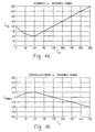
- Fig. 4a represents a plot of torque feedback T fb versus measured torque T m which illustrates the effect of the controller 14 in an open loop to closed loop transition.
- the torque command T c in the example of Fig. 4a is given to be constant at 128 units (half scale).
- the value of r is preselected to be 64.
- the controller 14 is in a steady state condition, e.g., the controller output T output equals the requested torque command T c .
- the torque feedback signal T fb gradually transitions from the steady state condition value of 128 to 64 as the measured torque (also having a full scale value of 256 units) increases from 0 to 64 units.
- the controller 14 operates in full closed loop fashion and the torque feedback signal T fb increases linearly with the measured torque T m .
- the feedback signal T fb would decrease linearly for values above r.
- the measured torque feedback signal T m is gradually cut out until the measured torque T m reaches zero.
- Fig. 4b represents the error signal T error plotted as a function of the measured torque T m under the same conditions set forth with respect to Fig. 4a. It is noted that the error signal T error is limited by the open loop control until the measured torque T m increases beyond 64 (the value of r).
- Fig. 5 is a plot illustrating the operation of the controller 14 in accordance with the embodiment of Fig. 3.
- the plot shown in Fig. 5 is to be compared with the plot shown in Fig. 6 which illustrates the corresponding operation of a controller which does not include torque level transitioning feedback in accordance with the invention.
- the controller represented in Fig. 6 exhibits large torque and pressure spikes (generally labeled as SP) at the application of braking from zero. Such spikes are avoided in the present invention as illustrated in Fig. 5.
- SP torque and pressure spikes
- the brake system with torque feedback control using torque level transitioning provides suitable torque compensation even to zero wheel speed. Moreover, by gradually transitioning between closed loop control and open loop control over a range of torque, smooth continuous braking is achievable.
- Equ. 1 assumes a linear relationship between the two signals which influence the function. Higher order relationships may be utilized without departing from the scope of the invention.
- torque cutout is performed within the range of zero to r.
- a different range from q to r may be defined where q is non-zero. Such an embodiment may be useful in the event full torque cutout is desired to occur prior to the measured torque reaching zero.
- a control mechanism other than the P-I type controller described above could be used to implement the invention.
- a PID type controller may be employed without departing from the scope of the invention.
- the control method of the present invention may be employed using parameters other than torque, particularly for vehicles which do not have torque sensors.
- braking may be controlled based on feedback relating to the acceleration of the vehicle.
- An accelerometer or other means for sensing acceleration provides a feedback signal in place of the torque sensor.
- the level transitioning controller determines the amount of feedback associated with the sensed acceleration using the same principles described above in place of the torque feedback signal.
Landscapes
- Engineering & Computer Science (AREA)
- Transportation (AREA)
- Mechanical Engineering (AREA)
- Aviation & Aerospace Engineering (AREA)
- Microelectronics & Electronic Packaging (AREA)
- Physics & Mathematics (AREA)
- Fluid Mechanics (AREA)
- Regulating Braking Force (AREA)
- Force Measurement Appropriate To Specific Purposes (AREA)
Claims (29)
- Unité de commande de transition de niveau de couple (14) destinée à commander un couple de freinage appliqué sur une roue (20) d'un véhicule par l'intermédiaire d'un actionneur et ensemble de freinage (16) sur la base d'une sortie d'un capteur de couple (22) qui mesure une valeur de couple de freinage appliqué sur la roue (20), la sortie du capteur de couple (22) étant réinjecté à l'unité de commande de transition de niveau de couple (14), l'unité de commande de transition de niveau de couple (14) comprenant ;
une entrée destinée à recevoir une instruction de couple de freinage représentative d'une valeur désirée d'un couple de freinage à appliquer sur la roue, et une sortie destinée à délivrer une instruction de sortie de couple de freinage à l'actionneur et ensemble de freinage qui applique un couple de freinage sur la roue, sur la base de l'instruction de sortie de couple de freinage ;
une autre entrée destinée à recevoir la sortie du capteur de couple ; et
des circuits destinés à régler l'instruction de sortie de couple de freinage délivrée à l'actionneur et ensemble de freinage en utilisant une commande d'asservissement de couple sur la base de la sortie reçue à partir du capteur de couple,
caractérisée en ce que
l'unité de commande de transition de niveau de couple (14) est configurée de manière à limiter un degré de commande d'asservissement de couple sur la base de la valeur mesurée du couple de freinage appliqué sur la roue (20). - Unité de commande selon la revendication 1, dans laquelle l'unité de commande de transition de niveau de couple tend vers l'application d'une commande en boucle ouverte sans commande d'asservissement de couple sur la base de la détection d'une faible valeur du couple de freinage appliqué sur la roue.
- Unité de commande selon la revendication 2, dans laquelle l'unité de commande de transition de niveau de couple utilise entièrement la commande d'asservissement de couple sur la base du signal provenant du capteur de couple en résultat du dépassement par le signal d'un seuil prédéterminé.
- Unité de commande selon la revendication 1, dans laquelle les circuits destinés à régler l'instruction de sortie de couple de freinage réalise des transitions entre une commande sensiblement en boucle ouverte de l'instruction de sortie de couple de freinage indépendamment du couple de freinage mesuré et une commande asservie sensiblement en boucle fermée de l'instruction de sortie de couple de freinage sur la base du couple de freinage mesuré en fonction du couple de freinage mesuré.
- Unité de commande selon la revendication 4, dans laquelle l'unité de commande de transition de niveau de couple réalise des transitions entre une commande en boucle sensiblement ouverte de l'instruction de sortie de couple de freinage et une commande asservie sensiblement en boucle fermée de l'instruction de sortie de couple de freinage sur une plage de couple de freinage mesuré en fonction du couple de freinage mesuré.
- Unité de commande selon la revendication 5, dans laquelle la fonction est représentée par une équation du premier ordre.
- Unité de commande selon la revendication 5, dans laquelle la fonction est représentée par une équation du deuxième ordre ou une équation d'ordre supérieur.
- Unité de commande selon la revendication 4, dans laquelle une fréquence à laquelle l'unité de commande de transition de niveau de couple réalise des transitions est commandée.
- Unité de commande selon la revendication 1, dans laquelle l'unité de commande devient moins sensible ou insensible à la valeur mesurée de couple de freinage appliqué sur la roue à des niveaux de couple de freinage faibles.
- Dispositif de commande d'un couple de freinage appliqué sur une roue d'un véhicule comprenant ;
l'unité de commande selon la revendication 1 ; et
un capteur de couple, couplé de manière opérationnelle à l'actionneur et ensemble de freinage et à l'unité de commande de transition de niveau de couple afin de mesurer une valeur de couple de freinage appliqué sur la roue et réinjectant un signal à l'unité de commande de transition de niveau de couple représentatif de la valeur de couple de freinage appliqué. - Unité de commande selon la revendication 10, dans laquelle l'unité de commande de transition de niveau de couple tend vers l'application d'une commande en boucle ouverte sans commande d'asservissement de couple sur la base de la détection d'une faible valeur de couple de freinage appliqué sur la roue.
- Dispositif selon la revendication 11, dans lequel l'unité de commande de transition de niveau de couple utilise entièrement la commande d'asservissement de couple sur la base du signal à partir du capteur de couple en résultat du dépassement, par le signal, d'un seuil prédéterminé.
- Dispositif selon la revendication 10, dans lequel l'instruction de sortie de couple de freinage est opérationnelle afin de commander une vanne de pression contenue dans l'actionneur et ensemble de freinage.
- Dispositif selon la revendication 10, dans lequel l'instruction de sortie de couple de freinage est opérationnelle afin de commander une vanne d'écoulement contenue dans l'actionneur et ensemble de freinage.
- Dispositif selon la revendication 14, comprenant, en outre, un capteur de pression destiné à mesurer la pression d'un fluide commandé par la vanne d'écoulement, la pression étant représentative d'une valeur d'un effort de freinage appliqué sur la roue, et dans lequel l'unité de commande de transition de niveau de couple reçoit la sortie du capteur de pression afin de réaliser une commande de pression en boucle fermée à de faibles niveaux de couple.
- Dispositif selon la revendication 10, dans lequel le véhicule est un avion.
- Dispositif selon la revendication 10, dans lequel le véhicule est une automobile.
- Dispositif selon la revendication 10, dans lequel l'unité de commande de transition de niveau de couple réalise des transitions entre une commande sensiblement en boucle ouverte de l'instruction de sortie de couple de freinage indépendamment du couple de freinage mesuré et une commande d'asservissement sensiblement en boucle fermée de l'instruction de sortie de couple de freinage sur la base du couple de freinage mesuré en fonction du couple de freinage mesuré.
- Dispositif selon la revendication 18, dans lequel l'unité de commande de transition de niveau de couple réalise des transitions entre une commande sensiblement en boucle ouverte de l'instruction de sortie de couple de freinage et une commande d'asservissement sensiblement en boucle fermée de l'instruction de sortie de couple de freinage sur une plage de couple de freinage mesuré en fonction du couple de freinage mesuré.
- Dispositif selon la revendication 19, dans lequel la fonction est représentée par une équation du premier ordre.
- Dispositif selon la revendication 19, dans lequel la fonction est représentée par une équation du deuxième ordre ou d'un ordre supérieur.
- Dispositif selon la revendication 18, dans lequel une fréquence à laquelle l'unité de commande de transition de niveau de couple réalise des transitions est commandée.
- Dispositif selon la revendication 18, dans lequel le véhicule est un avion.
- Dispositif selon la revendication 18, dans lequel le véhicule est une automobile.
- Procédé de commande d'un couple de freinage appliqué sur une roue (20) d'un véhicule comprenant les étapes de ;
réception d'une instruction de couple de freinage représentative d'une valeur désirée du couple de freinage à appliquer sur la roue (20) et fourniture d'une instruction de sortie de couple de freinage à un actionneur et ensemble de freinage (16) qui applique un couple de freinage sur la roue (20) sur la base de l'instruction de sortie de couple de freinage ;
mesure d'une valeur de couple de freinage appliqué sur la roue (20) et utilisation d'un signal représentatif de la valeur de couple de freinage appliqué afin de réaliser une commande d'asservissement de couple à partir de l'instruction de sortie de couple de freinage ; et
réglage de l'instruction de sortie de couple de freinage délivrée à l'actionneur de frein (16) en utilisant la commande d'asservissement de couple sur la base de la valeur mesurée de couple de freinage, l'étape de réglage comportant une étape de limitation d'un degré de la commande d'asservissement de couple sur la base de la valeur de couple de freinage appliqué sur la roue. - Procédé selon la revendication 25, dans lequel l'étape de limitation comporte la transition vers l'application d'une commande en boucle ouverte sans la commande d'asservissement de couple sur la base de la détection d'une faible valeur de couple de freinage appliqué sur la roue.
- Procédé selon la revendication 26, dans lequel l'étape de limitation comporte l'utilisation complète de la commande d'asservissement de couple sur la base du signal provenant du capteur de couple en résultat du dépassement, par le signal, d'un seuil prédéterminé.
- Procédé selon la revendication 25, dans lequel l'étape de réglage comporte, en outre, la transition entre une commande sensiblement en boucle ouverte de l'instruction de sortie de couple de freinage indépendamment du couple de freinage mesuré et une commande d'asservissement sensiblement en boucle fermée de l'instruction de sortie de couple de freinage sur la base du couple de freinage mesuré en fonction du couple de freinage mesuré.
- Procédé selon la revendication 28, dans lequel l'étape de transition comporte la transition entre une commande sensiblement en boucle ouverte de l'instruction de sortie de couple de freinage et une commande d'asservissement sensiblement en boucle fermée de l'instruction de sortie de couple de freinage sur une plage de couple de freinage mesuré en fonction du couple de freinage mesuré.
Applications Claiming Priority (2)
| Application Number | Priority Date | Filing Date | Title |
|---|---|---|---|
| US1572 | 1987-01-08 | ||
| US09/001,572 US6036285A (en) | 1997-12-31 | 1997-12-31 | Brake system using torque feedback control with torque level transitioning |
Publications (3)
| Publication Number | Publication Date |
|---|---|
| EP0927671A2 EP0927671A2 (fr) | 1999-07-07 |
| EP0927671A3 EP0927671A3 (fr) | 2000-03-22 |
| EP0927671B1 true EP0927671B1 (fr) | 2004-08-18 |
Family
ID=21696750
Family Applications (1)
| Application Number | Title | Priority Date | Filing Date |
|---|---|---|---|
| EP98310646A Expired - Lifetime EP0927671B1 (fr) | 1997-12-31 | 1998-12-23 | Système et procédé pour commander le freinage d'une roue de véhicule |
Country Status (5)
| Country | Link |
|---|---|
| US (1) | US6036285A (fr) |
| EP (1) | EP0927671B1 (fr) |
| JP (1) | JP4372253B2 (fr) |
| DE (1) | DE69825716T2 (fr) |
| IL (1) | IL127835A (fr) |
Cited By (1)
| Publication number | Priority date | Publication date | Assignee | Title |
|---|---|---|---|---|
| DE102017204639A1 (de) | 2017-03-21 | 2018-09-27 | Ford Global Technologies, Llc | Verfahren zum Abbremsen eines sich mit geringer Geschwindigkeit bewegenden Fahrzeugs |
Families Citing this family (26)
| Publication number | Priority date | Publication date | Assignee | Title |
|---|---|---|---|---|
| US6132016A (en) * | 1997-05-02 | 2000-10-17 | Hydro-Aire, Inc. | System and method for adaptive brake application and initial skid detection |
| US6722745B2 (en) * | 1997-05-02 | 2004-04-20 | Hydro-Aire, Inc. | System and method for adaptive brake application and initial skid detection |
| DE19742920A1 (de) * | 1997-09-29 | 1999-04-01 | Itt Mfg Enterprises Inc | Verfahren zum Aufbringen definierter Betätigungskräfte |
| WO2001036240A1 (fr) * | 1999-11-15 | 2001-05-25 | Newtech Mecatronic Inc. | Dispositif électronique de freinage |
| US7104616B2 (en) * | 2003-07-02 | 2006-09-12 | Goodrich Corporation | Brake gain-based torque controller |
| US7441844B2 (en) * | 2005-02-18 | 2008-10-28 | Hydro-Aire, Inc. | Method to reduce carbon brake wear through residual brake force |
| US20060226698A1 (en) * | 2005-04-11 | 2006-10-12 | Gary Riebe | Aircraft taxi speed control system and method |
| US7111611B1 (en) | 2005-09-21 | 2006-09-26 | Daimlerchrysler Corporation | Torque sensor-based engine and powertrain control system |
| US9085285B2 (en) | 2006-01-19 | 2015-07-21 | Hydro-Aire, Inc. | System and method for aircraft brake metering to alleviate structural loading |
| US7410224B2 (en) | 2006-01-19 | 2008-08-12 | Hydro-Aire, Inc. | Method and system to increase electric brake clamping force accuracy |
| US7640078B2 (en) * | 2006-07-05 | 2009-12-29 | Advanced Energy Industries, Inc. | Multi-mode control algorithm |
| US7571635B2 (en) * | 2007-05-02 | 2009-08-11 | Chrysler Group Llc | Engine knock detection system and method |
| FR2918945B1 (fr) * | 2007-07-19 | 2009-10-09 | Messier Bugatti Sa | Procede de commande d'un frein de vehicule avec correction en couple |
| US9604526B2 (en) * | 2008-12-05 | 2017-03-28 | Ford Global Technologies, Llc | Method for providing improved driveability for a vehicle |
| FR2941204B1 (fr) * | 2009-01-16 | 2011-02-25 | Messier Bugatti | Procede de commande d'un frein de vehicule avec correction en couple adaptative |
| US8197016B2 (en) * | 2009-05-01 | 2012-06-12 | Goodrich Corporation | Brake fill effect minimization function |
| US8131400B2 (en) * | 2010-06-10 | 2012-03-06 | Hitachi Metals, Ltd. | Adaptive on-tool mass flow controller tuning |
| KR101252250B1 (ko) * | 2011-10-10 | 2013-04-08 | 주식회사 만도 | 전자 제어식 브레이크 부스터 |
| DE102013222061A1 (de) * | 2013-03-25 | 2014-09-25 | Continental Teves Ag & Co. Ohg | Verfahren zum Betrieb einer Bremsanlage für Kraftfahrzeuge |
| US9463873B2 (en) * | 2014-07-13 | 2016-10-11 | The Boeing Company | Vehicle braking system having braking control and skid reduction functions |
| GB2540183A (en) * | 2015-07-08 | 2017-01-11 | Airbus Operations Ltd | Braking control system for an aircraft |
| JP6809413B2 (ja) * | 2017-08-22 | 2021-01-06 | トヨタ自動車株式会社 | 電子制御ブレーキシステム |
| US10894533B2 (en) * | 2017-12-22 | 2021-01-19 | Robert Bosch Gmbh | Wheel torque sensor for highly automated driving vehicles |
| EP3597496B1 (fr) | 2018-07-16 | 2020-09-02 | Safran Landing Systems UK Limited | Ensemble de train d'atterrissage d'aeronef |
| FR3099461B1 (fr) * | 2019-07-30 | 2021-08-13 | Safran Landing Systems | Dispositif de freinage d’une roue |
| US11975704B2 (en) * | 2021-01-05 | 2024-05-07 | The Boeing Company | Fault-tolerant brake load alleviation |
Family Cites Families (20)
| Publication number | Priority date | Publication date | Assignee | Title |
|---|---|---|---|---|
| US3614172A (en) * | 1969-02-27 | 1971-10-19 | Kelsey Hayes Co | Skid control system |
| US3586387A (en) * | 1969-03-05 | 1971-06-22 | Kelsey Hayes Co | Skid control system |
| US4043607A (en) * | 1975-02-07 | 1977-08-23 | Societe Nationale Industrielle Aerospatiale | Method and device for controlling disc brakes |
| AU3755378A (en) * | 1977-07-09 | 1980-01-03 | Dunlop Ltd | Brake overload control |
| US4336592A (en) * | 1980-06-23 | 1982-06-22 | Goodyear Aerospace Corporation | Antiskid control system for brakes which exhibit large changes in lining friction coefficient |
| US4412291A (en) * | 1980-09-30 | 1983-10-25 | The Boeing Company | Brake torque control system |
| WO1985002591A1 (fr) * | 1983-12-16 | 1985-06-20 | Robert Bosch Gmbh | Procede pour transformer le signal de sortie d'un capteur de mesure de vitesse de rotation en un signal pauvre en interferences |
| WO1985002592A1 (fr) * | 1983-12-16 | 1985-06-20 | Robert Bosch Gmbh | Procede pour determiner une valeur de glissement optimale |
| US4679866A (en) * | 1983-12-16 | 1987-07-14 | Robert Bosch Gmbh | Method for ascertaining the set-point braking moment for the various wheels of a vehicle |
| US4603763A (en) * | 1984-09-25 | 1986-08-05 | Mikina Stanley J | Drum brake with negative feedback for brake shoe friction compensation |
| US4822113A (en) * | 1987-08-13 | 1989-04-18 | The Boeing Company | Braking torque control system |
| US5050940A (en) * | 1990-02-05 | 1991-09-24 | Allied-Signal Inc. | Brake control and anti-skid system |
| DE4030653A1 (de) * | 1990-09-28 | 1992-04-02 | Bosch Gmbh Robert | Verfahren zum bestimmen der schraeglaufwinkel und/oder der seitenfuehrungskraefte eines gebremsten fahrzeuges |
| US5333706A (en) * | 1991-10-22 | 1994-08-02 | Akebono Brake Industry Co., Ltd. | Brake apparatus for a vehicle |
| US5180214A (en) * | 1991-12-30 | 1993-01-19 | National Science Council | Servo-type phase-locked loop anti-skid brake control system |
| US5424942A (en) * | 1993-08-10 | 1995-06-13 | Orbital Research Inc. | Extended horizon adaptive block predictive controller with an efficient prediction system |
| US5454630A (en) * | 1994-04-29 | 1995-10-03 | General Motors Corporation | Automotive antilock braking |
| US5487594A (en) * | 1994-11-30 | 1996-01-30 | Alliedsignal Inc. | Method for updating a wheel reference value by assessing proximity for the braking power curve peak |
| US5505531A (en) * | 1995-05-12 | 1996-04-09 | The Boeing Company | Method to maintain brake stack closure during autobrake application |
| US5918951A (en) * | 1997-05-09 | 1999-07-06 | The B.F. Goodrich Company | Antiskid brake control system using kalman filtering |
-
1997
- 1997-12-31 US US09/001,572 patent/US6036285A/en not_active Expired - Lifetime
-
1998
- 1998-12-23 DE DE69825716T patent/DE69825716T2/de not_active Expired - Lifetime
- 1998-12-23 EP EP98310646A patent/EP0927671B1/fr not_active Expired - Lifetime
- 1998-12-25 JP JP36893898A patent/JP4372253B2/ja not_active Expired - Fee Related
- 1998-12-29 IL IL12783598A patent/IL127835A/en not_active IP Right Cessation
Cited By (3)
| Publication number | Priority date | Publication date | Assignee | Title |
|---|---|---|---|---|
| DE102017204639A1 (de) | 2017-03-21 | 2018-09-27 | Ford Global Technologies, Llc | Verfahren zum Abbremsen eines sich mit geringer Geschwindigkeit bewegenden Fahrzeugs |
| US10532726B2 (en) | 2017-03-21 | 2020-01-14 | Ford Global Technologies, Llc | Method for decelerating a vehicle moving at low speed |
| DE102017204639B4 (de) * | 2017-03-21 | 2020-03-12 | Ford Global Technologies, Llc | Verfahren zum Abbremsen eines sich mit geringer Geschwindigkeit bewegenden Fahrzeugs |
Also Published As
| Publication number | Publication date |
|---|---|
| US6036285A (en) | 2000-03-14 |
| IL127835A (en) | 2002-09-12 |
| DE69825716D1 (de) | 2004-09-23 |
| EP0927671A2 (fr) | 1999-07-07 |
| DE69825716T2 (de) | 2005-08-25 |
| JPH11245785A (ja) | 1999-09-14 |
| IL127835A0 (en) | 1999-10-28 |
| EP0927671A3 (fr) | 2000-03-22 |
| JP4372253B2 (ja) | 2009-11-25 |
Similar Documents
| Publication | Publication Date | Title |
|---|---|---|
| EP0927671B1 (fr) | Système et procédé pour commander le freinage d'une roue de véhicule | |
| US6062336A (en) | Adaptive variable effort power steering system | |
| US5669678A (en) | Process and apparatus for determining the application pressures and characteristic brake values of a vehicle | |
| CA2039808C (fr) | Limiteur de lacet sur frein antiblocage | |
| US7104616B2 (en) | Brake gain-based torque controller | |
| US6226586B1 (en) | Foundation brake control algorithm for electro-hydraulic brake system and brake-by-wire system | |
| US5320422A (en) | Slip control device for vehicle wheel | |
| US6042196A (en) | Trailer brake control device of tractor-trailer combination vehicle for suppression of side sway of trailer | |
| EP0721877B1 (fr) | Appareil de commande du comportement d'un véhicule capable de changer la limite supérieure de sa sortie en fonction de la disponibilité d'un autre appareil de commande du comportement d'un véhicule | |
| US5390992A (en) | Vehicle electric brake system with static brake torque control | |
| US8332119B2 (en) | System for controlling a motor vehicle driving downhill | |
| US10625719B2 (en) | Method for adjusting brake pressures on pneumatically actuated wheel brakes of a vehicle, brake system for carrying out the method, and vehicle | |
| US8197016B2 (en) | Brake fill effect minimization function | |
| JPH0134822B2 (fr) | ||
| WO1998039184A9 (fr) | Systeme de commande de frein a indicateur de pedale de frein | |
| US6178370B1 (en) | Deceleration based antiskid brake contoller with adaptive deceleration threshold | |
| US5315518A (en) | Method and apparatus for initializing antilock brake control on split coefficient surface | |
| US5646848A (en) | Method for proportionally controlling the brakes of a vehicle based on tire deformation | |
| JPH1016737A (ja) | 車両のブレーキ装置を制御するための方法及び装置 | |
| US20090287388A1 (en) | System for controlling a vehicle driving downhill | |
| US4849890A (en) | Anti-skid braking system for automotive vehicle | |
| JPH0848229A (ja) | 四輪自動車用のアンチロック制御装置 | |
| US6116703A (en) | Process for the braking of a vehicle | |
| JP2979705B2 (ja) | 制動力制御装置 | |
| US4989921A (en) | Mine hoist brake regulator |
Legal Events
| Date | Code | Title | Description |
|---|---|---|---|
| PUAI | Public reference made under article 153(3) epc to a published international application that has entered the european phase |
Free format text: ORIGINAL CODE: 0009012 |
|
| AK | Designated contracting states |
Kind code of ref document: A2 Designated state(s): DE FR GB |
|
| AX | Request for extension of the european patent |
Free format text: AL;LT;LV;MK;RO;SI |
|
| PUAL | Search report despatched |
Free format text: ORIGINAL CODE: 0009013 |
|
| AK | Designated contracting states |
Kind code of ref document: A3 Designated state(s): AT BE CH CY DE DK ES FI FR GB GR IE IT LI LU MC NL PT SE |
|
| AX | Request for extension of the european patent |
Free format text: AL;LT;LV;MK;RO;SI |
|
| 17P | Request for examination filed |
Effective date: 20000425 |
|
| AKX | Designation fees paid |
Free format text: DE FR GB |
|
| RAP1 | Party data changed (applicant data changed or rights of an application transferred) |
Owner name: GOODRICH CORPORATION |
|
| 17Q | First examination report despatched |
Effective date: 20020528 |
|
| GRAP | Despatch of communication of intention to grant a patent |
Free format text: ORIGINAL CODE: EPIDOSNIGR1 |
|
| GRAS | Grant fee paid |
Free format text: ORIGINAL CODE: EPIDOSNIGR3 |
|
| GRAA | (expected) grant |
Free format text: ORIGINAL CODE: 0009210 |
|
| AK | Designated contracting states |
Kind code of ref document: B1 Designated state(s): DE FR GB |
|
| REG | Reference to a national code |
Ref country code: GB Ref legal event code: FG4D |
|
| REF | Corresponds to: |
Ref document number: 69825716 Country of ref document: DE Date of ref document: 20040923 Kind code of ref document: P |
|
| ET | Fr: translation filed | ||
| PLBE | No opposition filed within time limit |
Free format text: ORIGINAL CODE: 0009261 |
|
| STAA | Information on the status of an ep patent application or granted ep patent |
Free format text: STATUS: NO OPPOSITION FILED WITHIN TIME LIMIT |
|
| 26N | No opposition filed |
Effective date: 20050519 |
|
| PGFP | Annual fee paid to national office [announced via postgrant information from national office to epo] |
Ref country code: DE Payment date: 20091230 Year of fee payment: 12 |
|
| REG | Reference to a national code |
Ref country code: DE Ref legal event code: R119 Ref document number: 69825716 Country of ref document: DE Effective date: 20110701 |
|
| PG25 | Lapsed in a contracting state [announced via postgrant information from national office to epo] |
Ref country code: DE Free format text: LAPSE BECAUSE OF NON-PAYMENT OF DUE FEES Effective date: 20110701 |
|
| REG | Reference to a national code |
Ref country code: FR Ref legal event code: PLFP Year of fee payment: 18 |
|
| PGFP | Annual fee paid to national office [announced via postgrant information from national office to epo] |
Ref country code: GB Payment date: 20151125 Year of fee payment: 18 |
|
| PGFP | Annual fee paid to national office [announced via postgrant information from national office to epo] |
Ref country code: FR Payment date: 20151123 Year of fee payment: 18 |
|
| GBPC | Gb: european patent ceased through non-payment of renewal fee |
Effective date: 20161223 |
|
| REG | Reference to a national code |
Ref country code: FR Ref legal event code: ST Effective date: 20170831 |
|
| PG25 | Lapsed in a contracting state [announced via postgrant information from national office to epo] |
Ref country code: FR Free format text: LAPSE BECAUSE OF NON-PAYMENT OF DUE FEES Effective date: 20170102 |
|
| PG25 | Lapsed in a contracting state [announced via postgrant information from national office to epo] |
Ref country code: GB Free format text: LAPSE BECAUSE OF NON-PAYMENT OF DUE FEES Effective date: 20161223 |