EP0927695A2 - Aufwickelmaschine für elastischen Faden und Wickel - Google Patents
Aufwickelmaschine für elastischen Faden und Wickel Download PDFInfo
- Publication number
- EP0927695A2 EP0927695A2 EP98122239A EP98122239A EP0927695A2 EP 0927695 A2 EP0927695 A2 EP 0927695A2 EP 98122239 A EP98122239 A EP 98122239A EP 98122239 A EP98122239 A EP 98122239A EP 0927695 A2 EP0927695 A2 EP 0927695A2
- Authority
- EP
- European Patent Office
- Prior art keywords
- yarn
- bobbin
- section
- guide
- elastic
- Prior art date
- Legal status (The legal status is an assumption and is not a legal conclusion. Google has not performed a legal analysis and makes no representation as to the accuracy of the status listed.)
- Granted
Links
- 238000004804 winding Methods 0.000 description 26
- 230000003028 elevating effect Effects 0.000 description 2
- 239000004677 Nylon Substances 0.000 description 1
- 238000000034 method Methods 0.000 description 1
- 229920001778 nylon Polymers 0.000 description 1
- 229920000728 polyester Polymers 0.000 description 1
- 238000011144 upstream manufacturing Methods 0.000 description 1
Images



Classifications
-
- B—PERFORMING OPERATIONS; TRANSPORTING
- B65—CONVEYING; PACKING; STORING; HANDLING THIN OR FILAMENTARY MATERIAL
- B65H—HANDLING THIN OR FILAMENTARY MATERIAL, e.g. SHEETS, WEBS, CABLES
- B65H54/00—Winding, coiling, or depositing filamentary material
- B65H54/02—Winding and traversing material on to reels, bobbins, tubes, or like package cores or formers
- B65H54/28—Traversing devices; Package-shaping arrangements
- B65H54/34—Traversing devices; Package-shaping arrangements for laying subsidiary winding, e.g. transfer tails
- B65H54/346—Traversing devices; Package-shaping arrangements for laying subsidiary winding, e.g. transfer tails on or outwardly of the fully wound yarn package
-
- B—PERFORMING OPERATIONS; TRANSPORTING
- B65—CONVEYING; PACKING; STORING; HANDLING THIN OR FILAMENTARY MATERIAL
- B65H—HANDLING THIN OR FILAMENTARY MATERIAL, e.g. SHEETS, WEBS, CABLES
- B65H65/00—Securing material to cores or formers
- B65H65/005—Securing end of yarn in the wound or completed package
-
- B—PERFORMING OPERATIONS; TRANSPORTING
- B65—CONVEYING; PACKING; STORING; HANDLING THIN OR FILAMENTARY MATERIAL
- B65H—HANDLING THIN OR FILAMENTARY MATERIAL, e.g. SHEETS, WEBS, CABLES
- B65H67/00—Replacing or removing cores, receptacles, or completed packages at paying-out, winding, or depositing stations
- B65H67/04—Arrangements for removing completed take-up packages and or replacing by cores, formers, or empty receptacles at winding or depositing stations; Transferring material between adjacent full and empty take-up elements
- B65H67/044—Continuous winding apparatus for winding on two or more winding heads in succession
- B65H67/048—Continuous winding apparatus for winding on two or more winding heads in succession having winding heads arranged on rotary capstan head
-
- B—PERFORMING OPERATIONS; TRANSPORTING
- B65—CONVEYING; PACKING; STORING; HANDLING THIN OR FILAMENTARY MATERIAL
- B65H—HANDLING THIN OR FILAMENTARY MATERIAL, e.g. SHEETS, WEBS, CABLES
- B65H2701/00—Handled material; Storage means
- B65H2701/30—Handled filamentary material
- B65H2701/31—Textiles threads or artificial strands of filaments
- B65H2701/319—Elastic threads
Definitions
- the present invention relates to an elastic yarn take-up winder comprised of a traverse device provided with two bobbin holders, a contact roller, and a traverse guide, and a position transfer means for switching the positions of a bobbin holder in a winding position and a bobbin holder in a stand-by position, whereby a bobbin holder with an empty bobbin and a bobbin holder with a fully wound package are exchanged, and a yarn is transferred onto the empty bobbin when a package becomes full, and further relates to the elastic yarn package formed by the elastic yarn take-up winder.
- a conventional turret-type elastic yarn take-up winder which switches the positions of bobbin holders by rotating a turret to which two bobbin holders are attached such that when a package becomes full, the package is exchanged with the empty bobbin holder, enabling continuous yarn winding, is common in the art.
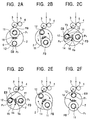
- the turret is operated to rotate in the counter-clockwise direction, moving the full bobbin from the winding position to an intermediary position, and the empty bobbin from the stand-by position to the intermediary position, and then stopped.
- a yarn winding guide which comprises the winding means winds the elastic yarn once around the empty bobbin, a high-speed brake is applied to the full bobbin, the elastic yarn is loosened, and a section of the yarn is adhered onto the surface of the empty bobbin.
- the yarn tension generated when the yarn section between the empty bobbin and the full bobbin is wound around the empty bobbin causes the yarn to break between the empty and full bobbins.
- the yarn which follows the yarn that is adhered onto the empty bobbin is wound on top of the new lead-end yarn tip, fixing it in place.
- the empty bobbin is returned to the winding position, and actual winding is carried out by the traverse device.
- the tail-end yarn tip is placed on the top yarn layer of the layered package wound by the take-up winder upon completion of winding.
- placing the tail-end yarn tip on top of the layered yarn is not a problem, but when the package is a wound package of elastic yarn, the adhesiveness of the elastic yarn may make finding and drawing out the tail-end yarn tip problematic at the next stage of processing.
- the present invention is an elastic yarn take-up winder provided with a yarn transfer means for transferring the yarn from a full bobbin to a empty bobbin, comprising a tail-end yarn guide for placing yarn introduced to the full bobbin at the end section of a bobbin, away from the layered yarn section of the bobbin, and a lead-end yarn guide for placing the yarn introduced to the empty bobbin at a position outside the yarn path along which the yarn is lead to the full bobbin.
- the present invention is an elastic yarn take-up winder in which the tail-end yarn guide is an independently moveable moving guide which moves along the bobbin in the bobbin's axial direction.
- the lead-end yarn guide is independently moveable along the bobbin in the bobbin's axial direction.
- a second invention of the present invention is an elastic yarn package in which the tails-end yarn tip is wound around the end section of a bobbin, away from the layered yarn section of the bobbin.
- the present invention is an elastic yarn package in which the lead-end yarn tip is wound at the layered yarn section of the bobbin.
- the present invention is an elastic yarn package in which the lead-end yarn tip is wound at the end section of a bobbin, away from the layered section of the bobbin, and on the opposite end of the bobbin as the end at which the tail-and yarn tip is wound.
- M is the elastic yarn take-up winder, comprised of a machine frame 7.
- the machine frame 7 is provided with an elevating box 1 which is enabled to independently rise and fall, a rotatable turret 2 and a fixed frame 8 on the front of which a control panel 9 is arranged.
- a contact roller 3 and a traverse device 4 are each held in the elevating box 1.
- the contact roller 3 applies pressure against the yarn layer surface of a bobbin B at a winding position P 1 .
- the contact roller 3 is rotationally driven by a driving source (not shown in the drawing) such that the bobbin B being wound is rotated in a counter-clockwise direction.
- a traverse guide 5 is arranged in the traverse device 4, and engages with an elastic yarn Y, traversing the elastic yarn Y by running within a traverse range.
- a yarn separating guide (not shown in the drawing) for separating the yarn from the traverse guide 5 is arranged in the upstream side of the traverse device 4.
- the turret 2 is rotatable via a rotational driving device (not shown in the drawing) centered around a rotary shaft 6.
- Two bobbin holders 11,12 are each held so as to jut out, and are independently rotatable in the turret 2.
- a plurality of bobbins B are inserted in each of the bobbin holders 11, 12, with one of the bobbin holders 11 arranged at the winding position P 1 and the other 12 at the stand-by position P 2 .
- Figure 4 in order to simplify the drawing, only one bobbin B is shown.
- the elastic yarn Y on the bobbin B of the bobbin holder 11 positioned at the winding position P 1 is wound, and when it becomes a full bobbin FB, the turret 2 is rotated.
- the full bobbin FB is moved from the winding position P 1 to the stand-by position P 2
- the pre-arranged empty bobbin EB at the stand-by position P 2 is moved from the stand-by position P 2 to the winding position P 1 .
- the elastic yarn Y is transferred from the full bobbin FB to the empty bobbin EB via a yarn exchange guide means 13, allowing yarn winding to continue uninterruptedly.
- the yarn exchange guide means 13 is comprised of tail-and yarn guide 14 and the lead-end yarn guide 15.
- the tails-end yarn guide 14 positions the yarn Y introduced to the full bobbin FB at an end section Ba of the bobbin B, away from the layered yarn section Pa. It may be comprised of a rod-shaped moving guide 16 with comb-like structures, and arranged so as to be independently moveable along the central axis of the bobbin B.
- the tail-end yarn guide 14 is attached to the turret 2 such that the rod-shaped moving guide 16 extends along the rotational axis of the turret 2, dividing the winding position bobbin holder and the stand-by position bobbin holder.
- the rod-shaped living guide 16 may move between the stand-by position at the far end Bb of the bobbin B shown by the double dotted chain line in Figure 4, and the near end Ba of the bobbin B indicated by the continuous line.
- the lead-end yarn guide 15 is comprised of a swinging arm 17 axially supported in the lower portion of the frame 7 and a guide bar 18 attached to the tip of the swinging arm 17.
- the swinging arm 17 is arranged on the side of the front ends of the bobbin holders 11, 12, and guide bar 18 is cantilevered from the front ends of the bobbin holders 11, 12 towards the base end of the bobbin holders 11, 12.
- the rotary shaft 19 of the swinging am 17 is arranged such that the elastic yarn Y can be wound around the empty bobbin EB by the guide bar 18 when the empty bobbin EB is at the yarn exchange position, or in other words, when it is at the intermediary position P 4 indicated by the double dotted chain line in Figure 1.
- the swinging arm 17 is normally set such that the guide bar 18 and other elements do not come into contact with the full bobbin FB when the turret 2 is rotated.
- the swinging arm 17 of the lead-end yarn guide 15 is arranged such that it can swing roughly 180 degrees around the center of the rotary axis 19 via a driving means such as a rotary actuator or the like (not shown in the drawing).
- the guide bar 18 of the lead-end yarn guide 15 is attached to the end of swinging am 17, and is provided with a guiding groove 20 shown in Figure 4, into which slides the elastic yarn Y.
- the guiding groove 20 is provided with two curved portions 21, 21 that taper in towards each other 21, 21. These curved portions 21, 21 help guide the elastic yarn Y along a curved path. By guiding the elastic yarn Y along the curved portions 21, 21, the yarn Y can be reliably guided to the bottom of the guiding groove 20.
- the lead-end yarn guide 15 may also be arranged so as to be independently moveable along the axial direction of the bobbin B, as indicated by the double dotted chain line in Figure 4.
- the lead-end yarn guide 15 moves in the axial direction of the bobbin B, the lead-end yarn tip is wound at the end section Bb of the bobbin B, away from the layered yarn section Pa of the bobbin B, and on the opposite end of the bobbin B from the end at which the tail-end yarn section is wound.
- the lead-end yarn guide 15 is operated.
- the lead-end yarn guide 15 catches the yarn section Ya of elastic yarn Y between the empty bobbin EB in the intermediary position P 4 and the full bobbin FB in the intermediary position P 3 , and moves it from the path indicated by the double dotted chain line in Figure 2C to the path indicated by the continuous line (changing the yarn path to that indicated by 1 ⁇ in Figure 3), in order to form the bunch winding in the middle section of the empty bobbin EB.
- the tail-end yarn guide 14 is operated from back to front in a direction perpendicular to the plane of the page, catching the yarn section Ya of the elastic yarn Y, and moving it from the path indicated by the double dotted chain line to the path indicated by the continuous line (changing the yarn path to that indicated by 2 ⁇ in Figure 3).
- the yarn section Ya is moved from the layered section Pa to the end section Ba of the full bobbin Fb.
- the tail end yarn tip is wound at the end section B of the full bobbin Fb.
- the tension of the yarn section Ya is reduced.
- the yarn section Ya is wound onto the surface of the empty bobbin EB.
- the yarn tension created when the yarn section Ya between the empty bobbin Eb and the full bobbin Fb causes the yarn to break between the empty bobbin EB and the full bobbin FB, and the yarn which follows the elastic yarn Y from the tail-end tip wound onto the empty bobbin EB is wound on top of the new lead-end yarn tip.
- the empty bobbin EB is returned to the winding position P 1 , as shown in Figure 2E and Figure 2F, and the actual winding is carried out with the traverse device 4.
- the lead-end yarn tip Yc is formed as a bunch winding in the middle section in the axial direction of the bobbin B (the middle section in the axial direction of the layered yarn section Pa), and the tail-end yarn tip Yd is moved from the layered yarn section Pa and wound around one end Ba of the bobbin B.
- the lead-end yarn tip Yc is moved from the layered yarn section Pa and wound at one end Bb of the bobbin B.
- the tail-end yarn tip Yd is moved from the layered yarn section Pa to the other end Ba of the bobbin B.
- the tail-end yarn tip Yd is wound onto one end of the bobbin Ba away from the layered yarn section Pa, and therefore the tail-end yarn tip Yd is very easy to find and draw out.
- the lead-end yarn tip Yc is wound onto a different end Bb of the bobbin B as the tail-end yarn tip Yd, and thus not only is the lead-end yarn tip Yc easy to find and draw out, but the lead-end yarn tip Yc and the tail-end yarn tip Yd do not overlap.
- the elastic yarn take-up winder which, by winding the tail-end yarn tip with the tail-end yarn guide which moves the yarn being led onto the full bobbin towards an end of the bobbin away from the layered yarn section of the bobbin, produces an elastic yarn package in which the tail-end yarn section can be easily found and drawn out, is provided. Further, the elastic yarn take-up winder for producing the elastic yarn package operates extremely effectively.
Landscapes
- Engineering & Computer Science (AREA)
- Textile Engineering (AREA)
- Replacing, Conveying, And Pick-Finding For Filamentary Materials (AREA)
- Winding Filamentary Materials (AREA)
- Spinning Or Twisting Of Yarns (AREA)
Applications Claiming Priority (2)
| Application Number | Priority Date | Filing Date | Title |
|---|---|---|---|
| JP9367866A JPH11193183A (ja) | 1997-12-29 | 1997-12-29 | 弾性糸用紡糸巻取機及び弾性糸パッケージ |
| JP36786697 | 1997-12-29 |
Publications (3)
| Publication Number | Publication Date |
|---|---|
| EP0927695A2 true EP0927695A2 (de) | 1999-07-07 |
| EP0927695A3 EP0927695A3 (de) | 1999-12-01 |
| EP0927695B1 EP0927695B1 (de) | 2004-09-15 |
Family
ID=18490403
Family Applications (1)
| Application Number | Title | Priority Date | Filing Date |
|---|---|---|---|
| EP98122239A Expired - Lifetime EP0927695B1 (de) | 1997-12-29 | 1998-11-23 | Aufwickelmaschine für elastischen Faden und Wickel |
Country Status (5)
| Country | Link |
|---|---|
| EP (1) | EP0927695B1 (de) |
| JP (1) | JPH11193183A (de) |
| KR (1) | KR100457500B1 (de) |
| DE (1) | DE69826230T2 (de) |
| TW (1) | TW415979B (de) |
Cited By (8)
| Publication number | Priority date | Publication date | Assignee | Title |
|---|---|---|---|---|
| EP1065163A3 (de) * | 1999-07-01 | 2001-08-01 | Murata Kikai Kabushiki Kaisha | Aufwickelmaschine und Verfahren dafür zum Bilden einer Fadenreserve |
| EP1129976A3 (de) * | 2000-03-01 | 2002-11-13 | Murata Kikai Kabushiki Kaisha | Elastisches-Garn Wickel und Aufwickelmaschine für elastische Garne |
| KR100457500B1 (ko) * | 1997-12-29 | 2005-06-28 | 무라타 기카이 가부시키가이샤 | 탄성사용방사권취기및탄성사패키지 |
| EP3321220A1 (de) * | 2016-11-14 | 2018-05-16 | Maschinenfabrik Rieter Ag | Verfahren zum definierten ablegen eines garnendes auf einer spule, vorrichtung und spinn- und wickelmaschine zur durchführung des verfahrens |
| CN108069291A (zh) * | 2016-11-14 | 2018-05-25 | 里特机械公司 | 用于以定义的方式将纱线端沉积在筒管上的方法、用于执行该方法的装置和纺纱卷绕机 |
| CN112011936A (zh) * | 2020-09-28 | 2020-12-01 | 绍兴联德机械设备有限公司 | 一种医用弹性无芯绷带卷生产线 |
| CN113443522A (zh) * | 2021-07-26 | 2021-09-28 | 伊东新(德阳)线缆设备有限公司 | 一种双盘收线机中线盘的控制方法 |
| EP4249414A1 (de) * | 2022-03-25 | 2023-09-27 | TMT Machinery, Inc. | Garnwickelmaschine |
Families Citing this family (3)
| Publication number | Priority date | Publication date | Assignee | Title |
|---|---|---|---|---|
| KR20040073675A (ko) * | 2003-02-14 | 2004-08-21 | 주식회사 효성 | 탄성사 방사 권취기의 오토 도핑 방법 |
| TWI786138B (zh) * | 2017-06-29 | 2022-12-11 | 日商東麗奧培隆特士股份有限公司 | 彈性紗卷層體捲裝 |
| KR20230130944A (ko) | 2022-03-04 | 2023-09-12 | 오상훈 | 차량용 트렁크 박스 |
Family Cites Families (12)
| Publication number | Priority date | Publication date | Assignee | Title |
|---|---|---|---|---|
| JPS5063242A (de) * | 1973-10-05 | 1975-05-29 | ||
| US4057195A (en) * | 1976-04-07 | 1977-11-08 | Owens-Corning Fiberglas Corporation | Apparatus for packaging strand |
| FR2425399A1 (fr) * | 1978-05-12 | 1979-12-07 | Saint Gobain | Perfectionnement au transfert d'un materiau filiforme d'une broche d'enroulement a une autre |
| EP0020078A1 (de) * | 1979-05-28 | 1980-12-10 | Nitto Boseki Co., Ltd. | Verfahren zum Verschieben von Seilen vor der Beendigung des Aufwickelns von Glasfasern |
| JPS59223665A (ja) * | 1983-05-25 | 1984-12-15 | Murata Mach Ltd | 糸条巻取装置 |
| JPS59223666A (ja) * | 1983-05-30 | 1984-12-15 | Murata Mach Ltd | 糸条巻取装置 |
| DE3711893A1 (de) * | 1987-04-08 | 1988-10-27 | Barmag Barmer Maschf | Verfahren zum anlegen eines mit konstanter geschwindigkeit angelieferten fadens an eine spulhuelse |
| DE68910762T2 (de) * | 1988-09-06 | 1994-03-31 | Asahi Chemical Ind | Methode zur automatischen Überführung eines elastischen Fadens von einer vollen auf eine leere Spule. |
| US4969607A (en) * | 1988-11-04 | 1990-11-13 | Rieter Machine Works Ltd. | Apparatus for introducing a yarn into the catch slot of an empty bobbin tube |
| US5566904A (en) * | 1993-04-23 | 1996-10-22 | Murata Kikai Kabushiki Kaisha | Method for sequentially winding elastic yarn on a plurality of bobbin holders |
| JP3168790B2 (ja) * | 1993-10-18 | 2001-05-21 | 村田機械株式会社 | 弾性糸の紡糸巻取方法及び紡糸巻取機 |
| JPH11193183A (ja) * | 1997-12-29 | 1999-07-21 | Murata Mach Ltd | 弾性糸用紡糸巻取機及び弾性糸パッケージ |
-
1997
- 1997-12-29 JP JP9367866A patent/JPH11193183A/ja active Pending
-
1998
- 1998-07-28 TW TW087112332A patent/TW415979B/zh not_active IP Right Cessation
- 1998-11-23 EP EP98122239A patent/EP0927695B1/de not_active Expired - Lifetime
- 1998-11-23 DE DE69826230T patent/DE69826230T2/de not_active Expired - Lifetime
- 1998-12-28 KR KR10-1998-0059129A patent/KR100457500B1/ko not_active Expired - Lifetime
Cited By (11)
| Publication number | Priority date | Publication date | Assignee | Title |
|---|---|---|---|---|
| KR100457500B1 (ko) * | 1997-12-29 | 2005-06-28 | 무라타 기카이 가부시키가이샤 | 탄성사용방사권취기및탄성사패키지 |
| EP1065163A3 (de) * | 1999-07-01 | 2001-08-01 | Murata Kikai Kabushiki Kaisha | Aufwickelmaschine und Verfahren dafür zum Bilden einer Fadenreserve |
| EP1129976A3 (de) * | 2000-03-01 | 2002-11-13 | Murata Kikai Kabushiki Kaisha | Elastisches-Garn Wickel und Aufwickelmaschine für elastische Garne |
| EP3321220A1 (de) * | 2016-11-14 | 2018-05-16 | Maschinenfabrik Rieter Ag | Verfahren zum definierten ablegen eines garnendes auf einer spule, vorrichtung und spinn- und wickelmaschine zur durchführung des verfahrens |
| CN108069285A (zh) * | 2016-11-14 | 2018-05-25 | 里特机械公司 | 用于以定义的方式将纱线端沉积在筒管上的方法、用于执行该方法的装置和纺纱卷绕机 |
| CN108069291A (zh) * | 2016-11-14 | 2018-05-25 | 里特机械公司 | 用于以定义的方式将纱线端沉积在筒管上的方法、用于执行该方法的装置和纺纱卷绕机 |
| US10400362B2 (en) | 2016-11-14 | 2019-09-03 | Maschinenfabrik Rieter Ag | Method for depositing a yarn end on a bobbin in a defined manner, a device and a spinning and winding machine for performing the method |
| CN108069285B (zh) * | 2016-11-14 | 2022-02-11 | 里特机械公司 | 用于以定义的方式将纱线端沉积在筒管上的方法、用于执行该方法的装置和纺纱卷绕机 |
| CN112011936A (zh) * | 2020-09-28 | 2020-12-01 | 绍兴联德机械设备有限公司 | 一种医用弹性无芯绷带卷生产线 |
| CN113443522A (zh) * | 2021-07-26 | 2021-09-28 | 伊东新(德阳)线缆设备有限公司 | 一种双盘收线机中线盘的控制方法 |
| EP4249414A1 (de) * | 2022-03-25 | 2023-09-27 | TMT Machinery, Inc. | Garnwickelmaschine |
Also Published As
| Publication number | Publication date |
|---|---|
| KR100457500B1 (ko) | 2005-06-28 |
| JPH11193183A (ja) | 1999-07-21 |
| DE69826230T2 (de) | 2005-11-17 |
| DE69826230D1 (de) | 2004-10-21 |
| EP0927695B1 (de) | 2004-09-15 |
| EP0927695A3 (de) | 1999-12-01 |
| TW415979B (en) | 2000-12-21 |
| KR19990063520A (ko) | 1999-07-26 |
Similar Documents
| Publication | Publication Date | Title |
|---|---|---|
| CN100354192C (zh) | 旋转型纱线卷绕机 | |
| EP0927695A2 (de) | Aufwickelmaschine für elastischen Faden und Wickel | |
| JPH0221485Y2 (de) | ||
| JPH02178183A (ja) | 巻取り中の糸の位置を変更する方法と装置 | |
| EP0927694B1 (de) | Garnwickelverfahren und -vorrichtung | |
| JP2001508750A (ja) | 連続的に供給される糸を巻き取るための方法および装置 | |
| JP3303850B2 (ja) | 紡糸巻取機、及びそのバンチ巻方法 | |
| US6158689A (en) | Yarn winding apparatus and method | |
| CN100480158C (zh) | 用于回转型自动络纱机的纱线引导装置 | |
| CN101331078A (zh) | 卷绕装置 | |
| JP2000327228A (ja) | 巻取機の糸掛装置 | |
| KR20010072348A (ko) | 사조의 절환방법 및 장치 | |
| JP4590156B2 (ja) | 弾性繊維用巻取り機 | |
| JP3965832B2 (ja) | 紡糸巻取機、及びその糸切換え方法 | |
| JPS59223666A (ja) | 糸条巻取装置 | |
| JP2000128435A (ja) | 合成繊維の巻取装置および巻取方法 | |
| KR100424985B1 (ko) | 방사권취기의 실전환방법 | |
| JP2563121Y2 (ja) | 紡糸巻取機 | |
| EP0231772A2 (de) | Fadenführung und Abschirmung für eine Spulmaschine | |
| RU2078734C1 (ru) | Способ намотки химической нити | |
| JP2718236B2 (ja) | 自動糸継ぎ機による巻取装置のクレードルアーム制御方法 | |
| JPH0615930Y2 (ja) | 巻取機の巻取切換装置 | |
| TW477773B (en) | Winding method in spun yarn winding machine and spun yarn winding machine | |
| JPS62218371A (ja) | 糸リザ−ブを形成する装置および方法 | |
| JPH082814A (ja) | 巻取装置 |
Legal Events
| Date | Code | Title | Description |
|---|---|---|---|
| PUAI | Public reference made under article 153(3) epc to a published international application that has entered the european phase |
Free format text: ORIGINAL CODE: 0009012 |
|
| AK | Designated contracting states |
Kind code of ref document: A2 Designated state(s): DE FR IT |
|
| AX | Request for extension of the european patent |
Free format text: AL;LT;LV;MK;RO;SI |
|
| PUAL | Search report despatched |
Free format text: ORIGINAL CODE: 0009013 |
|
| AK | Designated contracting states |
Kind code of ref document: A3 Designated state(s): AT BE CH CY DE DK ES FI FR GB GR IE IT LI LU MC NL PT SE |
|
| AX | Request for extension of the european patent |
Free format text: AL;LT;LV;MK;RO;SI |
|
| 17P | Request for examination filed |
Effective date: 20000228 |
|
| 17Q | First examination report despatched |
Effective date: 20000623 |
|
| AKX | Designation fees paid |
Free format text: DE FR IT |
|
| GRAP | Despatch of communication of intention to grant a patent |
Free format text: ORIGINAL CODE: EPIDOSNIGR1 |
|
| GRAS | Grant fee paid |
Free format text: ORIGINAL CODE: EPIDOSNIGR3 |
|
| GRAA | (expected) grant |
Free format text: ORIGINAL CODE: 0009210 |
|
| AK | Designated contracting states |
Kind code of ref document: B1 Designated state(s): DE FR IT |
|
| PG25 | Lapsed in a contracting state [announced via postgrant information from national office to epo] |
Ref country code: FR Free format text: LAPSE BECAUSE OF FAILURE TO SUBMIT A TRANSLATION OF THE DESCRIPTION OR TO PAY THE FEE WITHIN THE PRESCRIBED TIME-LIMIT Effective date: 20040915 |
|
| REF | Corresponds to: |
Ref document number: 69826230 Country of ref document: DE Date of ref document: 20041021 Kind code of ref document: P |
|
| PLBE | No opposition filed within time limit |
Free format text: ORIGINAL CODE: 0009261 |
|
| STAA | Information on the status of an ep patent application or granted ep patent |
Free format text: STATUS: NO OPPOSITION FILED WITHIN TIME LIMIT |
|
| 26N | No opposition filed |
Effective date: 20050616 |
|
| EN | Fr: translation not filed | ||
| REG | Reference to a national code |
Ref country code: DE Ref legal event code: R082 Ref document number: 69826230 Country of ref document: DE Representative=s name: WEICKMANN & WEICKMANN PATENT- UND RECHTSANWAEL, DE Ref country code: DE Ref legal event code: R082 Ref document number: 69826230 Country of ref document: DE Representative=s name: WEICKMANN & WEICKMANN PATENTANWAELTE - RECHTSA, DE Ref country code: DE Ref legal event code: R082 Ref document number: 69826230 Country of ref document: DE Representative=s name: PATENTANWAELTE WEICKMANN & WEICKMANN, DE |
|
| PGFP | Annual fee paid to national office [announced via postgrant information from national office to epo] |
Ref country code: DE Payment date: 20171121 Year of fee payment: 20 |
|
| PGFP | Annual fee paid to national office [announced via postgrant information from national office to epo] |
Ref country code: IT Payment date: 20171124 Year of fee payment: 20 |
|
| REG | Reference to a national code |
Ref country code: DE Ref legal event code: R071 Ref document number: 69826230 Country of ref document: DE |