EP0928259B1 - Ligne de rupture frontale d'un panneau de dissimulation d'air bag - Google Patents
Ligne de rupture frontale d'un panneau de dissimulation d'air bag Download PDFInfo
- Publication number
- EP0928259B1 EP0928259B1 EP97934295A EP97934295A EP0928259B1 EP 0928259 B1 EP0928259 B1 EP 0928259B1 EP 97934295 A EP97934295 A EP 97934295A EP 97934295 A EP97934295 A EP 97934295A EP 0928259 B1 EP0928259 B1 EP 0928259B1
- Authority
- EP
- European Patent Office
- Prior art keywords
- tear
- air bag
- edge
- seam
- door
- Prior art date
- Legal status (The legal status is an assumption and is not a legal conclusion. Google has not performed a legal analysis and makes no representation as to the accuracy of the status listed.)
- Expired - Lifetime
Links
- 230000003313 weakening effect Effects 0.000 title description 6
- 239000006260 foam Substances 0.000 claims description 17
- 238000000034 method Methods 0.000 claims description 11
- 239000000463 material Substances 0.000 description 6
- 229910052782 aluminium Inorganic materials 0.000 description 3
- XAGFODPZIPBFFR-UHFFFAOYSA-N aluminium Chemical compound [Al] XAGFODPZIPBFFR-UHFFFAOYSA-N 0.000 description 3
- 238000009751 slip forming Methods 0.000 description 3
- 125000000391 vinyl group Chemical group [H]C([*])=C([H])[H] 0.000 description 3
- 229920002554 vinyl polymer Polymers 0.000 description 3
- 230000000712 assembly Effects 0.000 description 2
- 238000000429 assembly Methods 0.000 description 2
- 230000002093 peripheral effect Effects 0.000 description 2
- 229920003023 plastic Polymers 0.000 description 2
- 239000004033 plastic Substances 0.000 description 2
- 230000000153 supplemental effect Effects 0.000 description 2
- JOYRKODLDBILNP-UHFFFAOYSA-N Ethyl urethane Chemical compound CCOC(N)=O JOYRKODLDBILNP-UHFFFAOYSA-N 0.000 description 1
- 239000004743 Polypropylene Substances 0.000 description 1
- 239000002131 composite material Substances 0.000 description 1
- 230000001419 dependent effect Effects 0.000 description 1
- 239000006263 elastomeric foam Substances 0.000 description 1
- 238000002844 melting Methods 0.000 description 1
- 230000008018 melting Effects 0.000 description 1
- 229910052751 metal Inorganic materials 0.000 description 1
- 239000002184 metal Substances 0.000 description 1
- 150000002739 metals Chemical class 0.000 description 1
- 239000002985 plastic film Substances 0.000 description 1
- 229920001155 polypropylene Polymers 0.000 description 1
- 239000004800 polyvinyl chloride Substances 0.000 description 1
- 238000005507 spraying Methods 0.000 description 1
- 229920002397 thermoplastic olefin Polymers 0.000 description 1
- 229920002803 thermoplastic polyurethane Polymers 0.000 description 1
- XLYOFNOQVPJJNP-UHFFFAOYSA-N water Substances O XLYOFNOQVPJJNP-UHFFFAOYSA-N 0.000 description 1
Images


Classifications
-
- B—PERFORMING OPERATIONS; TRANSPORTING
- B60—VEHICLES IN GENERAL
- B60R—VEHICLES, VEHICLE FITTINGS, OR VEHICLE PARTS, NOT OTHERWISE PROVIDED FOR
- B60R21/00—Arrangements or fittings on vehicles for protecting or preventing injuries to occupants or pedestrians in case of accidents or other traffic risks
- B60R21/02—Occupant safety arrangements or fittings, e.g. crash pads
- B60R21/16—Inflatable occupant restraints or confinements designed to inflate upon impact or impending impact, e.g. air bags
-
- B—PERFORMING OPERATIONS; TRANSPORTING
- B60—VEHICLES IN GENERAL
- B60R—VEHICLES, VEHICLE FITTINGS, OR VEHICLE PARTS, NOT OTHERWISE PROVIDED FOR
- B60R21/00—Arrangements or fittings on vehicles for protecting or preventing injuries to occupants or pedestrians in case of accidents or other traffic risks
- B60R21/02—Occupant safety arrangements or fittings, e.g. crash pads
- B60R21/16—Inflatable occupant restraints or confinements designed to inflate upon impact or impending impact, e.g. air bags
- B60R21/20—Arrangements for storing inflatable members in their non-use or deflated condition; Arrangement or mounting of air bag modules or components
- B60R21/215—Arrangements for storing inflatable members in their non-use or deflated condition; Arrangement or mounting of air bag modules or components characterised by the covers for the inflatable member
- B60R21/2165—Arrangements for storing inflatable members in their non-use or deflated condition; Arrangement or mounting of air bag modules or components characterised by the covers for the inflatable member characterised by a tear line for defining a deployment opening
-
- B—PERFORMING OPERATIONS; TRANSPORTING
- B60—VEHICLES IN GENERAL
- B60R—VEHICLES, VEHICLE FITTINGS, OR VEHICLE PARTS, NOT OTHERWISE PROVIDED FOR
- B60R21/00—Arrangements or fittings on vehicles for protecting or preventing injuries to occupants or pedestrians in case of accidents or other traffic risks
- B60R21/02—Occupant safety arrangements or fittings, e.g. crash pads
- B60R21/16—Inflatable occupant restraints or confinements designed to inflate upon impact or impending impact, e.g. air bags
- B60R21/20—Arrangements for storing inflatable members in their non-use or deflated condition; Arrangement or mounting of air bag modules or components
- B60R21/215—Arrangements for storing inflatable members in their non-use or deflated condition; Arrangement or mounting of air bag modules or components characterised by the covers for the inflatable member
- B60R21/2165—Arrangements for storing inflatable members in their non-use or deflated condition; Arrangement or mounting of air bag modules or components characterised by the covers for the inflatable member characterised by a tear line for defining a deployment opening
- B60R2021/21652—Arrangements for storing inflatable members in their non-use or deflated condition; Arrangement or mounting of air bag modules or components characterised by the covers for the inflatable member characterised by a tear line for defining a deployment opening the tearing being done or assisted by cutters
Definitions
- This invention relates generally to air bag restraint systems and more particularly to a cover assembly for concealing an air bag restraint system in a vehicle passenger compartment.
- supplemental inflatable restraints i.e., air bags
- cover assemblies that conceal the supplemental restraints. For primarily aesthetic reasons, it is desirable for such cover assemblies to include continuously formed outer skins or covers that provide no outward indication that an air bag assembly is concealed beneath or behind.
- One such method of controlling outer skin tearing is to create a weakened tear seam by weakening a linear portion of the outer skin so that tearing will occur along that weakened line when the air bag inflates. Weakening is sometimes accomplished by such means as perforating, cutting or melting the outer skin prior to assembling the cover assembly.
- the document US 5131678 assigned to the assignee of the present application discloses an air bag cover assembly that includes a weakened tear-seam formed in the outer surface of an outer skin prior to assembly by cutting. This document does not, however, provide for concealment of the weakened tear-seam from passenger compartment occupants.
- Another method of controlling outer-skin tearing is to use one or more pressure-assist members such as cutters or tear edges.
- the document US 4 097 064 discloses a cover assembly with a rigid applique in the form of a semi-rigid pad that is supported in a layered disposition over an outer skin.
- a cutter is mounted on the inner surface of the semi-rigid pad with a sharp cutting edge extended inward toward the outer skin.
- Air bag inflation forces the outer skin outward into contact with the inwardly-directed cutter, cutting the outer skin and releasing the inflating air bag.
- the position of the cutter on the inner surface of the pad also serves to conceal the cutter from vehicle occupants.
- the prior art also includes an air bag cover assembly that employs both outer-skin weakening and a tear edge positioned along the weakened tear seam.
- the document US 5 375 875 discloses a cover assembly with a weakened tear-seam formed in the inner surface of an outer skin, and a tear edge on a cutter panel that swings outwardly under the force of air bag inflation to cut the outer skin along the weakened tear-seam.
- the weakened tear seam is concealed from passenger compartment occupants by positioning it on the inner surface of the outer skin.
- a cover assembly that conceals an air bag restraint assembly.
- the cover assembly includes a weakened tear-seam formed in the outer surface of an outer skin, and a rigid applique that is supported in a layered disposition over the outer skin to conceal the weakened tear-seam from passenger compartment occupants.
- the outer skin is supported in a layered disposition across an outer surface of an inner retainer panel.
- the retainer panel is secured between the air bag and a vehicle passenger compartment and has an opening defined by forward, side and rear inner edges.
- An air bag door is shaped to fill the retainer panel opening when the door is in a closed position.
- the door has a hinged rear outer edge pivotally connected to the retainer panel along the rear inner edge of the retainer panel opening to allow the door to swing outwardly and away from the closed position when the door is exposed to a deploying air bag.
- the applique By concealing the weakened tear seam, the applique provides a more aesthetically-pleasing finished appearance while preventing tampering or access to the air bag compartment.
- One final aspect of the present invention includes a method, according to claim 19, for assembling an air bag cover that includes the step of weakening the outer skin during assembly by forcing a pressure assist member to cut into the outer surface of the outer skin as the pressure assist member is being attached to the air bag cover during assembly.
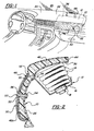
- a cover assembly for concealing an automotive vehicle air bag restraint assembly is generally indicated at 10 in Fig. 1.
- the cover assembly 10 is designed to be installed in the passenger compartment of an automobile.
- the cover assembly 10 is designed to conceal an air bag restraint assembly 12.
- the air bag restraint assembly 12 includes an air bag 14, an air bag housing 16 and a gas generator 18 for supplying gas to the air bag 14 in response to vehicle impact.
- the air bag restraint assembly 12 may be constructed as set forth in U.S. Pat. Nos. 5,154,444 and 5,316,335, both of which are assigned to the assignee of the present application.
- Fig. 1 the cover assembly 10 and the air bag restraint assembly 12 are shown in a top-mount position with a hidden door 36 in an upper surface 20 of a dashboard 22 underlying a sloped front windshield 24.
- the cover assembly 10 may, alternatively, be adapted to cover an air bag restraint assembly 12 mounted in other than a top-mount position, e.g., a mid-mount position with the hidden door 36 located in the front surface of an instrument panel or dashboard 22.
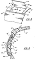
- the cover assembly indicated at 10 in Fig. 2 represents a first embodiment of the invention.
- a second embodiment is generally indicated at 10' in Fig. 4 and a third embodiment is generally indicated at 10" in Fig. 5.
- Reference numerals with the designation prime (') in Fig. 4 and the designation double-prime (") in Figs. 5-7 indicate alternative configurations of elements that also appear in the first or second embodiment. Where a portion of the following description uses a reference numeral to refer to the figures, I intend that portion of the description to apply equally to elements designated by primed and double-primed numerals in Figs. 4-7.
- the first embodiment comprises an inner retainer panel 26 that is adapted for securement between the air bag 14 and a vehicle passenger compartment.
- the retainer panel 26 is formed from a thin plastic panel but may, alternatively, be made of other suitably rigid materials. As is best shown in Fig. 3, the retainer panel 26 has a rectangular opening 28 defined by forward 30, side 32 and rear 34 inner edges.
- a rectangular air bag door 36 that fits within the rectangular retainer panel opening 28 when the door 36 is in a closed position.
- the door 36 is formed from the same gauge plastic sheet that the retainer panel 26 is formed from. Therefore, when the door 36 is in its closed position, the door outer and inner surfaces lie flush with the retainer panel outer and inner surfaces.
- the door 36 has forward 38 and side 40 outer edges running adjacent and parallel to the respective forward 30 and side 32 inner edges of the retainer panel opening 28 when the door 36 is in the closed position.
- the door 36 has a rear hinge 42 that pivotally connects the door 36 to the retainer panel 26 along the rear inner edge 34 of the retainer panel opening 28. As shown in Fig. 3, this arrangement allows the door 36 to swing outwardly and away from the closed position when the door 36 is exposed to a deploying air bag 14.
- the rear hinge 42 may pivotally connect the door 36 to the air bag housing 16.
- a layer 44 of energy-absorbing elastomeric foam such as urethane foam, is supported in a layered disposition across and is bonded to an outer surface of the retainer panel 26.
- the foam layer 44 also extends across and is bonded to an outer surface of the air bag door 36.
- the foam layer 44 can be applied as described in U.S. Pat. No. 5,154,444 or by spraying or by being formed as a preform and then attached thereto.
- the foam may, alternatively, be supplied as part of the skin layer.
- Examples of such composite skin/foam structures include expanded vinyl sheet materials or polyvinylchloride (PVC)/polypropylene foam bilaminates.
- the outer skin 46 is supported in a layered disposition on and is bonded to an outer surface of the foam layer 44.
- the outer skin 46 can be formed from cast vinyl material by processes such as those set forth in U.S. Pat. Nos. 4,664,864 and 4,784,911, both of which are assigned the assignee of the present application.
- the outer skin 46 may, alternatively, be formed from materials other than vinyl, such as thermoplastic polyolefins and thermoplastic urethanes that exhibit suitable flexibility and tear characteristics under a wide range of operating temperatures from below 0 degrees Fahrenheit to above 100 degrees Fahrenheit. Rather than being cast, the outer skin may also be sprayed-on or supplied as a sheet.
- a weakened tear-seam 48 is formed in an outer surface of the outer skin 46.
- the weakened tear-seam 48 runs parallel to and adjacent the forward outer edge 38 of the air bag door 36.
- the weakened tear seam 48 turns at a point adjacent each of two forward corners 88, 90 of the retainer panel opening 28 and runs parallel to and along the sides 32 of the retainer panel opening 28.
- the tear seam 48 provides a guide to initiate and direct outer skin 46 tearing along the sides 32 of the retainer panel opening 28 when the air bag inflates and forces the air bag door 36 to open.
- the weakened tear-seam 48 of the first embodiment is an actual gap that is cut, melted or otherwise formed through the entire thickness of the outer skin 46.
- the weakened tear-seam 48 may, alternatively, comprise a row of closely-spaced perforations or a groove that has been cut, melted or otherwise formed part way into the outer surface or inner surface of the outer skin 46.
- the tear seam 48 can be shaped as a molded or cut V-groove or a series of spaced perforated holes formed by a laser beam or other known precision cutters such as water jets or the like.
- the weakened tear seam 48 may be formed in the outer skin 46 either prior to, during or after the air bag cover 10 is assembled and either before, during or after the air bag cover assembly 10 is mounted over the air bag restraint assembly 12.
- the tear seam 48 may instead be formed either independently or in some combination with a pressure-assist member, such as a cutter or tear edge, that is attached over the outer skin 46 during assembly.
- a pressure-assist member such as a cutter or tear edge
- the pressure-assist member As the pressure-assist member is mounted, it forms the tear seam 48 as the pressure-assist member is forced into the outer surface of the outer skin 46. After the pressure-assist member has been secured in its assembled position, its cutting surface remains embedded within the tear seam 48 as shown in Figs. 4, 4A, 4B and 5 or may completely sever the outer skin 46.
- the pressure-assist member may not engage the skin 46 upon attachment, but only upon deployment whereby the skin 46 is forced into the pressure-assist member.
- a rigid applique 50 of extruded aluminum is supported in a layered disposition over the outer skin 46.
- a peripheral edge 52 of the applique 50 extends over and conceals the weakened tear-seam 48 from passenger compartment occupants.
- the applique 50 is spaced from the outer skin 46 and is shaped to match the contours of the skin 46 and to cover the front edge 38 to prevent tampering therewith so as to prevent access to the undeployed bag 14.
- the applique 50 is supported on the retainer panel 26 by one or more tie-down posts 53.
- Through-holes for receiving the tie-down posts 53 extend through the skin 46, foam layer 44 and retainer panel 26.
- the tie-down posts 53 project integrally inward from a central portion of the retainer and pass through the through-holes.
- a distal end of each post 53 is adapted to receive a fastener 54.
- the fastener 54 may be any one of a number of suitable fasteners commonly known in the art such as screws, rivets, barbed fasteners and the like.
- each post 53 has a tapered base 56 that engages a tapered outer end 55 of a through-hole in skin section 46a, preventing the applique 50 from contacting the outer skin 46, i.e., the tapered outer end 55 serves as a reference surface for spacing the applique 50 from the outer surface of the outer skin 46.
- Variations on the first embodiment may include a retainer panel opening 28 that has a shape other than rectangular, an air bag door 36 that is formed from a different material than the retainer panel 26 or that has a thickness or gauge different from that of the retainer panel 26, or an applique 50 made of plastic or suitable metals.
- a second embodiment of the present invention includes a rigid elongated tear edge 58 that is disposed outside the outer skin 46' and is supported on the applique 50' in a position directly over and along the weakened tear-seam 48'.
- the tear edge 58 has a generally triangular cross-section, as shown in Figs. 4 and 9, and runs the entire length of the weakened tear seam 48'.
- the tear edge 58 is extruded with the applique 50' so that the tear edge 58 and applique 50' form a single unitary extruded aluminum piece.
- the tear edge 58 projects integrally inwardly toward the weakened tear-seam 48' from an inner surface of the applique 50'.
- the tear edge 58 is supported in a generally perpendicular orientation in relation to the outer skin 46' and presents a relatively sharp, elongated cutting edge to the weakened tear-seam 48'. As shown in Fig. 9, the tear edge 58 turns at a point adjacent each of two forward corners 88, 90 of the retainer panel opening 28 and runs parallel and adjacent the sides 32 of the retainer panel opening 28. By running parallel to the sides 32 of the retainer panel opening 28, the tear edge 58 helps to initiate and direct outer skin 46 side-tearing when the air bag inflates and forces the air bag door 36 to open.
- the weakened tear-seam 48' of the second embodiment comprises an inwardly-projecting corrugation 60.
- the tear edge 58 extends inwardly into the corrugation 60 and laterally along the length of the corrugation 60.
- a first variant of the second embodiment is generally indicated at 10'A in Fig. 4A and a second variant is generally indicated at 10'B in Fig. 4B.
- Reference numerals with the suffix "A” in Fig. 4A and the suffix "B” in Fig. 4B indicate alternative configurations of elements that also appear in the second embodiment. Where a portion of the preceding description uses a reference numeral to refer to the figures, that portion of the description applies equally to elements designated by the suffix "A” or "B” in Figs. 4A and 4B.
- the first variant of the second embodiment includes no air bag door 36'. Instead, a portion of the over-lying foam layer 44'A and a portion of the outer skin 46'A serve the function of an air bag door by concealing the air bag assembly and breaking open upon air bag inflation.
- the portion of the foam layer 44'A and outer skin 46'A that serves the function of an air bag door is that portion of each that overlies the retainer panel opening shown at 28 in Fig. 3 and, as shown in Fig. 4A, is disposed on the air bag side of the tear edge 58A. As the air bag inflates through the retainer panel opening 28 it forces the foam layer 44'A and outer skin 46'A outward against the tear edge 58A.
- the tear edge 58A cuts the outer skin 46'A and foam layer 44'A to form an escape door for the inflating air bag.
- the second variant of the second embodiment includes no foam layer 44' between the outer skin 46'B and the retainer panel 26'B. Instead, the outer skin 46'B is bonded directly to the retainer panel 26'B and the air bag door 36'B.
- the forward outer edge 38'B of the air bag door 36'B and the forward inner edge 30'B of the retainer panel opening run adjacent and parallel to each other along opposite sides of the weakened tear seam 48'B.
- the air bag door 36'B is forced outward which forces the weakened tear seam 48'B of the outer skin 46'B into contact with the tear edge 58B.
- the tear edge 58B cuts the outer skin 46'B along the tear seam 48'B and initiates lateral tearing along the sides 32 of the retainer panel opening. This allows the air bag door 36'H to swing open, releasing the inflating air bag.
- the second embodiment may include a tear edge 58 formed separately of aluminum or other suitable materials and attached to the applique inner surface.
- the tear-seam may comprise a simple cut, gap or row of perforations alone in the outer skin 46 as described, above, with regard to the first embodiment, or it may act in combination with the tear edge 58.
- the tear edge 58 may partially or fully sever the skin 46 prior to deployment upon its attachment.
- the tear edge 58" is supported on an elongated tear bracket 62 instead of being supported on the applique 50" as in the second embodiment.
- the tear bracket 62 is supported on the retainer panel 26" and supports the tear edge 58" in a position parallel to and adjacent the weakened tear-seam 48".
- the tear edge 58" projects integrally inward toward the weakened tear-seam 48" to present a relatively sharp, elongated cutting edge to the weakened tear-seam 48" with the tear edge 58" having a generally perpendicular orientation in relation to the outer skin 46".
- the tear edge 58" of the third embodiment extends inwardly from along the tear bracket 62 instead of the applique 50" as is best shown in Fig. 5.
- the tear bracket 62 and tear edge 58" are disposed behind a peripheral edge 52" of the applique 50" so that the applique 50" conceals the tear bracket 62 and tear edge 58" from occupants.
- At least one fastener 64 is disposed between the tear bracket 62 and the retainer panel 26". Fasteners 64 pass through holes in bar 70 as is schematically shown in Figures 6 and 7. Each fastener 64 has an outer end, or “head” connected to the tear bracket 62. The head holds the tear bracket 62 inward against the outer skin 46. An inner end of the fastener 34 is connected to the retainer panel 26" by well-known means such as the nut 66 shown in Fig. 5.
- the foam panel 44" includes a shallow elongated inward recess 68 disposed between the applique 50" and the retainer panel 26" and along and adjacent the weakened tear-seam 48".
- the recess 68 is shaped to receive the tear bracket 62 in a counter-sunk disposition and the outer skin 46" is conformed to the shape of the recess 68.
- the tear bracket 62 is disposed along and within the recess 68. When the tear bracket 62 is mounted in the recess 68, the outer surface of the tear bracket 62 lies in a generally coplanar relationship with the outer surface of the outer skin 46".
- the tear bracket 62 comprises an elongated bar 70 extending parallel to and adjacent the weakened tear-seam 48" between two bracket ends 72, 74.
- the tear edge 58" comprises a series of fillets or serrations which form peaks 76 along the length of the tear edge 58".
- the peaks 76 serve to puncture the outer skin 46 at spaced locations along the weakened tear seam 48".
- the tear bracket 62 also includes first 78 and second 80 perpendicular extensions.
- the extensions 78, 80 integrally project from the bar ends 72, 74, respectively, and extend parallel to and adjacent the retainer panel opening side inner edges 32.
- the bar 70 and the perpendicular extensions 78, 80 define an elongated U-shape.
- At least one tear edge side piece 84 is supported on each of the two perpendicular extensions 78, 80.
- the third embodiment includes two tear edge side pieces, i.e., an inner 82 and an outer 84 tear edge side piece on each perpendicular extension 78, 80.
- the tear edge side pieces 82, 84 are triangular in shape.
- Each tear edge side piece 82, 84 is connected to the outer edge of a perpendicular extension 78, 80 along one triangular side of the respective side piece 82, 84.
- a triangular apex of each tear edge side piece 82, 84 extends inward from its respective perpendicular extension 78, 80.
- Each inner tear edge side piece 82 has the shape of a right triangle.
- Each inner tear edge side piece 82 is integrally formed as a unitary piece with one of the outermost peaks 86 of the main tear edge 58" to form a corner spike at each end of the tear bracket 62.
- the tear edge side pieces 82, 84 are supported on the perpendicular bracket extensions 78, 80 so as to be positioned along the outer skin 46" where the outer skin 46" covers the interface between the side inner edges 32 of the retainer panel opening 28 and the side outer edges of the air bag door 36.
- the tear edge side pieces are therefore positioned over this seam to initiate cover tearing along the air bag door side outer edges - allowing the air bag door 36" to open in response to air bag inflation.
- Variations on the third embodiment may include the use of suitable fasteners other than fasteners 34 to attach the tear bracket 62 to the retainer panel 26".
- the tear edge 58" may comprise a single straight sharp cutting edge without fillets or may comprise any number of other cutting configurations as are commonly known in the art.
- Other variations may include more than two tear edge side pieces 82, 84 on each perpendicular extension 78, 80 and tear edge side pieces 82, 84 that are other than triangular in shape.
- the tear edge side pieces 82, 84 may, for example, comprise a continuous, straight cutting edge rather than a series of spikes or serrations.
Landscapes
- Engineering & Computer Science (AREA)
- Mechanical Engineering (AREA)
- Air Bags (AREA)
- Instrument Panels (AREA)
Claims (23)
- Cache (10 ; 10' ; 10'A ; 10'B ; 10") destiné à dissimuler un ensemble (12) de contention d'un coussin gonflable de sécurité dans un véhicule automobile, l'ensemble (12) de contention englobant un coussin gonflable de sécurité (14), un logement (16) de coussin gonflable de sécurité, et un générateur (18) de gaz situé dans le logement (16) afin de fournir du gaz au coussin gonflable de sécurité (14) en réponse à un choc du véhicule, ledit cache (10 ; 10' ; 10'A ; 10'B ; 10") comprenant :un panneau de retenue intérieur (26 ; 26' ; 26'A ; 26'B ; 26") qui est apte à une fixation entre le coussin gonflable de sécurité (14) et l'habitacle du véhicule, ledit panneau de retenue (26 ; 26' ; 26'A ; 26'B ; 26") comportant une ouverture (28) définie par des bords intérieurs avant (30), latéraux (32) et arrière (24) ; une trappe (36 ; 36' ; 36'B ; 36") pour le coussin gonflable de sécurité conformée pour obturer ladite ouverture (28) du panneau de retenue lorsque ladite trappe (36 ; 36' ; 36'B ; 36") est dans une position fermée, ladite trappe (36 ; 36' ; 36'B ; 36") ayant des bords extérieurs avant (38) et latéraux (40) courants adjacents et parallèles auxdits bords intérieurs avant (30) et latéraux (32) de ladite ouverture (28) du panneau de retenue lorsque ladite trappe (36 ; 36' ; 36'B ; 36") est dans ladite position fermée, ladite trappe (36 ; 36' ; 36'B ; 36") ayant un bord extérieur arrière articulé (42) relié de manière pivotante à l'un dudit panneau de retenue (26 ; 26'; 26'A ; 26'B ; 26") et dudit logement (16) de coussin gonflable de sécurité de manière contiguë audit bord intérieur arrière (34) de ladite ouverture (28) du panneau de retenue afin de permettre à ladite trappe (36 ; 36' ; 36'B ; 36") de basculer vers l'extérieur et de quitter ladite position fermée lorsque ladite trappe (36 ; 36' ; 36'B ; 36") est exposée au coussin gonflable de sécurité (14) lorsque le coussin gonflable de sécurité (14) se déploie ; un revêtement extérieur (46 ; 46' ; 46'A ; 46'B ; 46") supporté selon une disposition en couches transversalement à une surface extérieure dudit panneau de retenue (26 ; 26' ; 26'A ; 26'B ; 26") et transversalement à une surface extérieure de ladite trappe (36 ; 36' ; 36'B ; 36") pour le coussin gonflable de sécurité ; une soudure affaiblie déchirable (48 ; 48' ; 48'A ; 48'B ; 48") formée dans ledit revêtement extérieur (46 ; 46' ; 46'A ; 46'B ; 46"), ladite soudure affaiblie déchirable (48 ; 48' ; 48'A ; 48'B ; 48") courant parallèlement et de manière adjacente audit bord extérieur avant (38) de ladite trappe (36 ; 36' ; 36'B ; 36") ; caractérisé en ce que le perfectionnement comprend :une applique rigide (50 ; 50' ; 50'A ; 50'B ; 50") reçue selon une disposition en couches sur ledit revêtement extérieur (46 ; 46' ; 46'A ; 46'B ; 46") et comprenant une portion de bordure (52 ; 52' ; 52'A ; 52'B ; 52") sur celui-ci recouvrant ladite soudure affaiblie déchirable (48 ; 48' ; 48'A ; 48'B ; 48") afin de dissimuler ladite soudure affaiblie déchirable (48 ; 48' ; 48'A ; 48'B ; 48").
- Cache (10' ; 10'A ; 10'B ; 10") selon la revendication 1, comprenant de plus une bordure rigide de déchirement (58 ; 58A ; 58B ; 58") disposée à l'extérieur dudit revêtement extérieur (46' ; 46'A ; 46'B ; 46") et directement au-dessus et le long de ladite soudure affaiblie déchirable (48' ; 48'A ; 48'B ; 48").
- Cache (10' ; 10'A ; 10'B ; 10") selon la revendication 2, dans lequel une portion de ladite bordure rigide de déchirement (58 ; 58A ; 58B ; 58") s'étend dans et le long de ladite soudure affaiblie déchirable (48' ; 48'A ; 48'B ; 48").
- Cache (10' ; 10'A; 10'B ; 10") selon la revendication 2, dans lequel une portion de ladite bordure de déchirement (58 ; 58A ; 58B ; 58") s'étend en totalité à travers ladite soudure affaiblie déchirable (48' ; 48'A ; 48'B ; 48").
- Cache (10' ; 10'A ; 10'B ; 10") selon la revendication 2, dans lequel une portion de ladite bordure de déchirement (58 ; 58A ; 58B ; 58") est supportée par ladite applique (50 ; 50' ; 50'A ; 50'B ; 50").
- Cache (10' ; 10'A ; 10'B ; 10") selon la revendication 5, dans lequel ladite applique (50' ; 50'A ; 50'B ; 50") est supportée par ledit panneau de retenue (26' ; 26'A ; 26'B ; 26").
- Cache (10' ; 10'A ; 10'B ; 10") selon la revendication 5, dans lequel ladite bordure de déchirement (58 ; 58A ; 58B ; 58") fait saillie intégralement vers l'intérieur en direction de ladite soudure affaiblie déchirable (48' ; 48'A ; 48'B ; 48") depuis une surface intérieure de ladite applique (50' ; 50'A ; 50'B ; 50").
- Cache (10' ; 10'A ; 10'B ; 10") selon la revendication 7, dans lequel une portion de ladite bordure de déchirement (58 ; 58A ; 58B ; 58") s'étend dans et le long de ladite soudure affaiblie déchirable (48' ; 48'A ; 48'B ; 48").
- Cache (10' ; 10'A ; 10'B ; 10") selon la revendication 7, dans lequel une portion de ladite bordure de déchirement (58 ; 58A ; 58B ; 58") s'étend en totalité à travers ladite soudure affaiblie déchirable (48' ; 48'A ; 48'B ; 48").
- Cache (10") selon la revendication 2, comprenant de plus une patte déchirable allongée (62) supportée par ledit panneau de retenue (26"), ladite patte déchirable (62) s'étendant parallèlement et de manière adjacente à ladite soudure affaiblie déchirable (48"), ladite bordure de déchirement (58") étant supportée par ladite patte déchirable (62).
- Cache (10") selon la revendication 10, dans lequel ladite bordure de déchirement (58") fait saillie intégralement vers l'intérieur en direction de ladite soudure affaiblie déchirable (48") depuis le long de ladite patte déchirable (62).
- Cache (10") selon la revendication 11, dans lequel ladite bordure de déchirement (58") s'étend dans et le long de ladite soudure affaiblie déchirable (48").
- Cache (10") selon la revendication 11, dans lequel une portion de ladite bordure de déchirement (58") s'étend en totalité à travers ladite soudure affaiblie déchirable (48").
- Cache (10 ") selon la revendication 10, dans lequel ladite patte déchirable (62) et ladite bordure de déchirement (58") sont disposées derrière ladite applique (50").
- Cache selon la revendication 2, dans lequel ladite soudure affaiblie déchirable (48' ; 48'A ; 48'B ; 48") comporte une ondulation (60 ; 60A ; 60B ; 60") saillant intérieurement et dans lequel ladite bordure de déchirement (58 ; 58A ; 58B ; 58") s'étend dans ladite ondulation (60 ; 60A ; 60B ; 60").
- Cache (10'') selon la revendication 10, comprenant de plus une couche de mousse (44") supportée selon une disposition en couches transversalement à une surface extérieure dudit panneau de retenue (26") et transversalement à une surface extérieure de ladite trappe (36") pour le coussin gonflable de sécurité, ledit revêtement extérieur (46") étant supporté selon une disposition en couches sur une surface extérieure de ladite couche de mousse (44").
- Cache (10") selon la revendication 16, dans lequel ledit panneau de mousse (44") comporte un évidement intérieur allongé peu profond (68) disposé entre ladite applique (50") et ledit panneau de retenue (26") et le long et adjacent à ladite soudure affaiblie déchirable (58"), ledit évidement (68) étant conformé pour recevoir ladite patte déchirable (62) selon une disposition noyée, ladite patte déchirable (62) étant disposée le long et dans ledit évidement (68) avec une surface extérieure de ladite patte (68) qui est globalement coplanaire avec une surface extérieure dudit revêtement extérieur (46").
- Cache (10") selon la revendication 10, dans lequel ladite patte déchirable (62) s'étend entre une première et une deuxième extrémités (78, 80), et dans lequel ledit cache (10") comprend une première (82) et une deuxième (84) pièces latérales de bordure de déchirement supportées par lesdites première et deuxième extrémités respectives (78, 80) de la patte déchirable, lesdites pièces latérales (82, 84) comprenant des bords tranchants respectifs positionnés à l'extérieur dudit revêtement extérieur (46") et alignés le long d'un plan s'étendant perpendiculairement vers l'extérieur depuis le long desdits bords latéraux extérieurs (40) de ladite trappe (36") pour le coussin gonflable.
- Procédé de fabrication d'un cache (10 ; 10' ; 10'A ; 10'B ; 10") destiné à dissimuler un ensemble (12) de contention d'un coussin gonflable de sécurité dans un véhicule automobile, l'ensemble (12) de contention englobant un coussin gonflable de sécurité (14), un logement (16) de coussin gonflable de sécurité, et un générateur (18) de gaz situé dans le logement (16) afin de fournir du gaz au coussin gonflable de sécurité (14) en réponse à un choc du véhicule, ledit cache (10 ; 10' ; 10'A ; 10'B ; 10") comprenant un panneau intérieur de retenue (26 ; 26' ; 26'A ; 26'B ; 26") qui est apte à une fixation entre le coussin gonflable de sécurité (14) et l'habitacle du véhicule, le panneau de retenue (26 ; 26' ; 26'A ; 26'B ; 26") comportant une ouverture (28) définie par des bords intérieurs avant (30), latéraux (32) et arrière (34) ; une trappe (36 ; 36' ; 36'B ; 36") pour le coussin gonflable de sécurité conformée pour obturer ladite ouverture (28) du panneau de retenue lorsque ladite trappe (36 ; 36' ; 36'B ; 36") est dans une position fermée, la trappe (36 ; 36' ; 36'B ; 36") ayant des bords extérieurs avant (38) et latéraux (40) courants adjacents et parallèles auxdits bords intérieurs avant (30) et latéraux (32) de l'ouverture (28) du panneau de retenue lorsque la trappe (36 ; 36' ; 36'B ; 36") est dans la position fermée, la trappe (36 ; 36' ; 36'B ; 36") ayant un bord extérieur arrière articulé (42) relié de manière pivotante à l'un d'entre le panneau de retenue (26 ; 26' ; 26'A ; 26'B ; 26") et le logement (16) de coussin gonflable de sécurité de manière contiguë au bord intérieur arrière (34) de l'ouverture (28) du panneau de retenue afin de permettre à la trappe (36 ; 36' ; 36'B ; 36") de basculer vers l'extérieur et de quitter la position fermée lorsque la trappe (36 ; 36' ; 36'B ; 36") est exposée au coussin gonflable de sécurité (14) lorsque le coussin gonflable de sécurité (14) se déploie ; un revêtement extérieur (46 ; 46' ; 46'A ; 46'B ; 46") supporté selon une disposition en couches transversalement à une surface extérieure du panneau de retenue (26 ; 26' ; 26'A ; 26'B ; 26") et transversalement à une surface extérieure de la trappe (36 ; 36' ; 36'B ; 36") pour le coussin gonflable de sécurité ; et une bordure de déchirement rigide (58 ; 58A ; 58B ; 58") disposée à l'extérieur du revêtement extérieur (46 ; 46' ; 46'A ; 46'B ; 46") ; caractérisé en ce que ledit procédé comprend les étapes de :réalisation d'une soudure affaiblie déchirable (48' ; 48'A ; 48'B ; 48") dans une surface extérieure du revêtement extérieur de telle sorte que la soudure (48' ; 48'A ; 48'B ; 48") coure parallèlement et de manière adjacente au bord extérieur avant (38) de la trappe (36 ; 36' ; 36'B ; 36'') ;
etinstallation de la bordure de déchirement (58 ; 58A ; 58B ; 58") à l'extérieur du revêtement extérieur (46' ; 46'A ; 46'B ; 46") avec une portion de la bordure de déchirement s'étendant dans et le long de ladite soudure affaiblie déchirable (48' ; 48'A ; 48'B ; 48"). - Procédé selon la revendication 19, dans lequel l'étape de réalisation comprend l'enfoncement de la bordure de déchirement (58 ; 58A ; 58B ; 58") dans la surface extérieure du revêtement extérieur (46' ; 46'A ; 46'B ; 46") pour former la soudure affaiblie déchirable (48' ; 48'A ; 48'B ; 48") courant parallèlement et de manière adjacente au bord extérieur avant (38) de la trappe (36 ; 36' ; 36'B ; 36").
- Procédé selon la revendication 20, dans lequel ladite étape d'enfoncement de la bordure de déchirement (58 ; 58A ; 58B ; 58") dans la surface extérieure du revêtement extérieur (46' ; 46'A ; 46'B ; 46") est réalisée pendant ladite étape d'installation de la bordure de déchirement (58 ; 58A ; 58B ; 58").
- Procédé selon la revendication 21, comprenant de plus l'étape supplémentaire d'enfoncement complet de la bordure de déchirement (58 ; 58A ; 58B ; 58") à travers le revêtement extérieur (46' ; 46'A ; 46'B ; 46") pendant ladite étape d'installation de la bordure de déchirement (58 ; 58A ; 58B ; 58").
- Procédé selon la revendication 19, dans lequel ladite étape de réalisation d'une soudure affaiblie déchirable (48' ; 48'A ; 48'B ; 48") dans la surface extérieure (46' ; 46'A ; 46'B ; 46") du revêtement et ladite étape d'installation de la bordure de déchirement (58 ; 58A ; 58B ; 58") sont réalisées simultanément.
Applications Claiming Priority (3)
| Application Number | Priority Date | Filing Date | Title |
|---|---|---|---|
| US08/719,004 US5806880A (en) | 1996-09-24 | 1996-09-24 | Frontal weakening of invisible air bag door cover |
| US719004 | 1996-09-24 | ||
| PCT/US1997/013030 WO1998013233A1 (fr) | 1996-09-24 | 1997-07-24 | Ligne de rupture frontale d'un panneau de dissimulation d'air bag |
Publications (3)
| Publication Number | Publication Date |
|---|---|
| EP0928259A1 EP0928259A1 (fr) | 1999-07-14 |
| EP0928259A4 EP0928259A4 (fr) | 2003-01-02 |
| EP0928259B1 true EP0928259B1 (fr) | 2005-12-28 |
Family
ID=24888422
Family Applications (1)
| Application Number | Title | Priority Date | Filing Date |
|---|---|---|---|
| EP97934295A Expired - Lifetime EP0928259B1 (fr) | 1996-09-24 | 1997-07-24 | Ligne de rupture frontale d'un panneau de dissimulation d'air bag |
Country Status (8)
| Country | Link |
|---|---|
| US (2) | US5806880A (fr) |
| EP (1) | EP0928259B1 (fr) |
| JP (1) | JP2001501150A (fr) |
| KR (1) | KR100707153B1 (fr) |
| AU (1) | AU3739097A (fr) |
| CA (1) | CA2266369A1 (fr) |
| DE (1) | DE69734991T2 (fr) |
| WO (1) | WO1998013233A1 (fr) |
Families Citing this family (31)
| Publication number | Priority date | Publication date | Assignee | Title |
|---|---|---|---|---|
| US5806880A (en) * | 1996-09-24 | 1998-09-15 | Davidson Textron Inc. | Frontal weakening of invisible air bag door cover |
| JP3944245B2 (ja) * | 1997-01-20 | 2007-07-11 | アリベル・インデュストリ | 通路を生成できるよう設計されたゾーンを含む完成部品を生産する方法、およびそれによって生産される完成部品およびアセンブリ |
| JP2998745B2 (ja) * | 1997-10-09 | 2000-01-11 | トヨタ自動車株式会社 | エアバッグドア部を一体に有するインストルメントパネル |
| US6168188B1 (en) * | 1998-07-09 | 2001-01-02 | Patent Holding Company | Motor vehicle instrument panel having integrally hinged air bag door |
| US6398256B1 (en) * | 1999-02-22 | 2002-06-04 | Kansei Corporation | Vehicle instrument panel |
| DE19912107A1 (de) * | 1999-03-18 | 2000-09-21 | Porsche Ag | Innenverkleidungsteil, insbesondere Instrumententafel für Kraftfahrzeuge |
| GB2350330A (en) * | 1999-04-30 | 2000-11-29 | Lear Automotive Dearborn Inc | Instrument panel with tear seam formed after moulding |
| DE19955221A1 (de) * | 1999-11-17 | 2001-05-23 | Behr Gmbh & Co | Instrumententafel eines Kraftfahrzeuges, insbesondere eines Personenkraftwagens |
| DE10037208A1 (de) * | 2000-07-31 | 2002-02-14 | Volkswagen Ag | Anordnung eines Airbagmoduls in der Innenverkleidung von Fahrzeugen |
| US20060012153A1 (en) * | 2000-12-08 | 2006-01-19 | Acts Advanced Car Technology Systems Gmbh & Co. Kg | Airbag system for motor vehicle integrated in an inner trim piece |
| US6409256B1 (en) * | 2001-01-23 | 2002-06-25 | Guardian Industries Corp. | Multi-piece applique for vehicle B-pillar |
| US6652128B2 (en) * | 2001-01-31 | 2003-11-25 | Textron Automotive Company, Inc. | Backlighting method for an automotive trim panel |
| GB2375086B (en) * | 2001-05-05 | 2004-10-20 | Visteon Global Tech Inc | In-tank fuel supply unit |
| DE10315622A1 (de) * | 2003-04-04 | 2004-11-25 | Peguform Gmbh & Co. Kg | Sicherheitseinrichtung in einer Seitenverkleidung eines Fahrzeugs |
| DE10316818B4 (de) * | 2003-04-11 | 2015-07-16 | Volkswagen Ag | Befestigungsanordnung für eine Dekorleiste als Airbagverkleidung an einem Fahrzeug |
| JP2005053250A (ja) * | 2003-08-01 | 2005-03-03 | Honda Motor Co Ltd | 自動車用エアバッグ装置 |
| WO2005021309A2 (fr) * | 2003-08-21 | 2005-03-10 | Collins & Aikman Products Co. | Tableau de bord recouvert de tissu |
| KR100520551B1 (ko) * | 2003-10-10 | 2005-10-11 | 현대자동차주식회사 | 인비져블 에어백용 피에이비 도어 설계 방법 |
| US20050104338A1 (en) * | 2003-11-19 | 2005-05-19 | Quin Soderquist | Applique film airbag cover |
| JP2007522958A (ja) * | 2003-12-31 | 2007-08-16 | コリンズ・アンド・アイクマン・プロダクツ・コーポレーション | 主基材に対する装飾製品のインモールドラミネーション |
| DE102006028047B4 (de) * | 2006-06-19 | 2015-03-05 | Audi Ag | Vorrichtung zur Befestigung eines Verkleidungsteils an einem Trägerteil im Innenraum eines Kraftfahrzeuges |
| KR100797134B1 (ko) * | 2006-10-27 | 2008-01-23 | 에스앤티대우(주) | 슬림형 조수석 에어백 모듈을 적용한 저 상해치 조수석에어백 시스템 |
| DE102007005922B4 (de) * | 2007-02-06 | 2010-11-18 | Lisa Dräxlmaier GmbH | Richtungsgeber für die Entfaltung eines Airbags |
| KR100980929B1 (ko) * | 2007-11-15 | 2010-09-07 | 기아자동차주식회사 | 하우징리스 타입 조수석 에어백 장치 |
| IT1393410B1 (it) * | 2008-10-24 | 2012-04-20 | Maserati Spa | Sistema di bloccaggio del rivestimento estetico sulla plancia di un veicolo che assicura la corretta apertura dello sportello air bag integrato. |
| IT1394101B1 (it) * | 2009-03-26 | 2012-05-25 | Adler Evo S R L | Pannello di rivestimento senza cuciture a rottura migliorata per air bag e metodo di fabbricazione |
| US8511706B2 (en) * | 2010-09-22 | 2013-08-20 | Automotive Components Holdings, Llc | Air bag deployment system with deflector rib |
| JP2012111424A (ja) * | 2010-11-26 | 2012-06-14 | Toyota Motor Corp | インストルメントパネルモジュール |
| WO2013029240A1 (fr) * | 2011-08-30 | 2013-03-07 | Faurecia (Shanghai) Management Company, Ltd | Ensemble garniture pour recouvrir un coussin de sécurité gonflable |
| JP5895814B2 (ja) * | 2012-10-26 | 2016-03-30 | 豊田合成株式会社 | 車両用内装パネル及び車両用エアバッグ装置 |
| US9533649B2 (en) * | 2014-05-07 | 2017-01-03 | Ford Global Technologies, Llc | Seamless passenger airbag system |
Family Cites Families (13)
| Publication number | Priority date | Publication date | Assignee | Title |
|---|---|---|---|---|
| JPS5243233A (en) * | 1975-09-30 | 1977-04-05 | Nissan Motor Co Ltd | Cushion cover for air cushion device |
| US4664864A (en) | 1983-06-03 | 1987-05-12 | Ex-Cell-O Corporation | Mold loading method and apparatus |
| US4784911A (en) | 1984-09-24 | 1988-11-15 | Ex-Cell-O Corporation | Three-dimensional multi-color plastic parts and method of making same |
| JPH01144153U (fr) * | 1988-03-11 | 1989-10-03 | ||
| US5375875A (en) * | 1993-10-05 | 1994-12-27 | Tip Engineering Group, Inc. | Two stage cutter arrangement for forming an air bag deployment opening |
| US5035444A (en) * | 1990-10-22 | 1991-07-30 | Davidson Textron Inc. | Single cutter self-piercing cover assembly for airbag |
| US5131678A (en) * | 1990-12-03 | 1992-07-21 | Davidson Textron Inc. | Invisible air bag cover door |
| US5154444A (en) * | 1991-04-05 | 1992-10-13 | Davidson Textron Inc. | Air bag retainer with cutting flaps |
| US5280947A (en) * | 1992-11-02 | 1994-01-25 | Davidson Textron Inc. | One piece invisible airbag door and hinge |
| US5316335A (en) * | 1992-12-14 | 1994-05-31 | Davidson Textron Inc. | Self piercing cover assembly air bag |
| US5447328A (en) * | 1994-05-31 | 1995-09-05 | Davidson Textron | Trim panel having integral door cover |
| US5466000A (en) * | 1994-11-17 | 1995-11-14 | Morton International, Inc. | Flat-lying cutter/ripper foldable into upstanding position during deployment of a vehicle airbag for detaching a deployment door from a panel |
| US5806880A (en) * | 1996-09-24 | 1998-09-15 | Davidson Textron Inc. | Frontal weakening of invisible air bag door cover |
-
1996
- 1996-09-24 US US08/719,004 patent/US5806880A/en not_active Expired - Fee Related
-
1997
- 1997-07-24 EP EP97934295A patent/EP0928259B1/fr not_active Expired - Lifetime
- 1997-07-24 WO PCT/US1997/013030 patent/WO1998013233A1/fr not_active Ceased
- 1997-07-24 AU AU37390/97A patent/AU3739097A/en not_active Abandoned
- 1997-07-24 KR KR1019997002531A patent/KR100707153B1/ko not_active Expired - Fee Related
- 1997-07-24 JP JP10515618A patent/JP2001501150A/ja not_active Ceased
- 1997-07-24 CA CA002266369A patent/CA2266369A1/fr not_active Abandoned
- 1997-07-24 DE DE69734991T patent/DE69734991T2/de not_active Expired - Fee Related
-
1998
- 1998-09-14 US US09/152,566 patent/US5992876A/en not_active Expired - Fee Related
Also Published As
| Publication number | Publication date |
|---|---|
| CA2266369A1 (fr) | 1998-04-02 |
| EP0928259A1 (fr) | 1999-07-14 |
| DE69734991T2 (de) | 2006-08-24 |
| JP2001501150A (ja) | 2001-01-30 |
| US5806880A (en) | 1998-09-15 |
| US5992876A (en) | 1999-11-30 |
| KR20000048597A (ko) | 2000-07-25 |
| KR100707153B1 (ko) | 2007-04-13 |
| AU3739097A (en) | 1998-04-17 |
| DE69734991D1 (de) | 2006-02-02 |
| EP0928259A4 (fr) | 2003-01-02 |
| WO1998013233A1 (fr) | 1998-04-02 |
Similar Documents
| Publication | Publication Date | Title |
|---|---|---|
| EP0928259B1 (fr) | Ligne de rupture frontale d'un panneau de dissimulation d'air bag | |
| JP3009208B2 (ja) | エアバッグ展開開口の閉鎖部材およびその表皮のカット方法 | |
| US5738367A (en) | Automotive interior trim piece having an arrangement for forming an air bag deployment opening | |
| US6443484B2 (en) | Decorative covering for air bag covers | |
| US6976701B2 (en) | Airbag door and method for making same | |
| US6070901A (en) | Automotive instrument panel having an integral airbag | |
| US5280947A (en) | One piece invisible airbag door and hinge | |
| EP0639481A1 (fr) | Méthode et traitement pour réaliser une ouverture de déploiement de sac gonflable dans une garniture reconverte de cuir | |
| EP0684168A1 (fr) | Agencement pour fournir une ouverture de déploiement de sac gonflable | |
| US7793972B2 (en) | Front pillar trim panel with tether | |
| CZ292850B6 (cs) | Díl obložení vnitřního prostoru pro automobily s airbagem | |
| JP2001502996A (ja) | エアバッグカバー | |
| US6942243B2 (en) | Vehicle instrument panel air bag door assembly | |
| US6921105B2 (en) | Integrally molded passenger airbag cover | |
| JP3039250U (ja) | 展開ドアの脱離装置を備えた乗物用エアバッグ装置及び自動車パネル組体 | |
| US7093850B2 (en) | Instrument panel with integral hidden door cover and method of manufacture thereof | |
| US10703318B2 (en) | Instrument panel with passenger airbag | |
| US6045153A (en) | Instrument panel cover arrangement and method of making | |
| US20080315566A1 (en) | Instrument panel with integral hidden door cover and method of manufacture thereof | |
| US20070246918A1 (en) | Instrument panel with integral hidden door cover and method of manufacture thereof | |
| JPH07329677A (ja) | エアバッグ装置のリッド | |
| JP3035058B2 (ja) | 自動車のエアバッグ装置 | |
| MXPA99002746A (en) | Frontal weakening of invisible air bag cover | |
| MXPA99003753A (en) | Interior trim panel for motor vehicles fitted with an airbag |
Legal Events
| Date | Code | Title | Description |
|---|---|---|---|
| PUAI | Public reference made under article 153(3) epc to a published international application that has entered the european phase |
Free format text: ORIGINAL CODE: 0009012 |
|
| 17P | Request for examination filed |
Effective date: 19990417 |
|
| AK | Designated contracting states |
Kind code of ref document: A1 Designated state(s): DE GB IT |
|
| A4 | Supplementary search report drawn up and despatched |
Effective date: 20021114 |
|
| AK | Designated contracting states |
Kind code of ref document: A4 Designated state(s): DE GB IT |
|
| RIC1 | Information provided on ipc code assigned before grant |
Free format text: 7B 60R 21/16 A, 7B 60R 21/20 B |
|
| 17Q | First examination report despatched |
Effective date: 20040730 |
|
| GRAP | Despatch of communication of intention to grant a patent |
Free format text: ORIGINAL CODE: EPIDOSNIGR1 |
|
| GRAS | Grant fee paid |
Free format text: ORIGINAL CODE: EPIDOSNIGR3 |
|
| GRAA | (expected) grant |
Free format text: ORIGINAL CODE: 0009210 |
|
| AK | Designated contracting states |
Kind code of ref document: B1 Designated state(s): DE GB IT |
|
| PG25 | Lapsed in a contracting state [announced via postgrant information from national office to epo] |
Ref country code: IT Free format text: LAPSE BECAUSE OF FAILURE TO SUBMIT A TRANSLATION OF THE DESCRIPTION OR TO PAY THE FEE WITHIN THE PRE;WARNING: LAPSES OF ITALIAN PATENTS WITH EFFECTIVE DATE BEFORE 2007 MAY HAVE OCCURRED AT ANY TIME BEFORE 2007. THE CORRECT EFFECTIVE DATE MAY BE DIFFERENT FROM THE ONE RECORDED.SCRIBED TIME-LIMIT Effective date: 20051228 |
|
| REG | Reference to a national code |
Ref country code: GB Ref legal event code: FG4D |
|
| REF | Corresponds to: |
Ref document number: 69734991 Country of ref document: DE Date of ref document: 20060202 Kind code of ref document: P |
|
| PLBE | No opposition filed within time limit |
Free format text: ORIGINAL CODE: 0009261 |
|
| STAA | Information on the status of an ep patent application or granted ep patent |
Free format text: STATUS: NO OPPOSITION FILED WITHIN TIME LIMIT |
|
| 26N | No opposition filed |
Effective date: 20060929 |
|
| PGFP | Annual fee paid to national office [announced via postgrant information from national office to epo] |
Ref country code: DE Payment date: 20081210 Year of fee payment: 12 |
|
| PGFP | Annual fee paid to national office [announced via postgrant information from national office to epo] |
Ref country code: GB Payment date: 20090116 Year of fee payment: 12 |
|
| GBPC | Gb: european patent ceased through non-payment of renewal fee |
Effective date: 20090724 |
|
| PG25 | Lapsed in a contracting state [announced via postgrant information from national office to epo] |
Ref country code: GB Free format text: LAPSE BECAUSE OF NON-PAYMENT OF DUE FEES Effective date: 20090724 |
|
| PG25 | Lapsed in a contracting state [announced via postgrant information from national office to epo] |
Ref country code: DE Free format text: LAPSE BECAUSE OF NON-PAYMENT OF DUE FEES Effective date: 20100202 |