EP0929009A2 - Détecteur de densité de toner, tête à jet d'encre, unité de développement et appareil de formation d'images dans lequel ce détecteur est utilisé - Google Patents
Détecteur de densité de toner, tête à jet d'encre, unité de développement et appareil de formation d'images dans lequel ce détecteur est utilisé Download PDFInfo
- Publication number
- EP0929009A2 EP0929009A2 EP99100494A EP99100494A EP0929009A2 EP 0929009 A2 EP0929009 A2 EP 0929009A2 EP 99100494 A EP99100494 A EP 99100494A EP 99100494 A EP99100494 A EP 99100494A EP 0929009 A2 EP0929009 A2 EP 0929009A2
- Authority
- EP
- European Patent Office
- Prior art keywords
- liquid developer
- toner density
- density sensor
- light
- light emitting
- Prior art date
- Legal status (The legal status is an assumption and is not a legal conclusion. Google has not performed a legal analysis and makes no representation as to the accuracy of the status listed.)
- Granted
Links
Images


Classifications
-
- G—PHYSICS
- G03—PHOTOGRAPHY; CINEMATOGRAPHY; ANALOGOUS TECHNIQUES USING WAVES OTHER THAN OPTICAL WAVES; ELECTROGRAPHY; HOLOGRAPHY
- G03G—ELECTROGRAPHY; ELECTROPHOTOGRAPHY; MAGNETOGRAPHY
- G03G15/00—Apparatus for electrographic processes using a charge pattern
- G03G15/06—Apparatus for electrographic processes using a charge pattern for developing
- G03G15/10—Apparatus for electrographic processes using a charge pattern for developing using a liquid developer
- G03G15/104—Preparing, mixing, transporting or dispensing developer
- G03G15/105—Detection or control means for the toner concentration
Definitions
- the present invention relates to a toner density sensor, and an ink jet head, a developing unit and an image forming apparatus in which a toner density sensor same is used, and more particularly to a toner density sensor for a wet type image forming apparatus such as a printer, a facsimile or a copying machine, and an ink jet head, a developing unit and an image forming apparatus in which a toner density sensor is used.
- a wet type image forming apparatus uses liquid developer composed of toner dispersed in solution to develop an electrostatic latent image formed on a photosensitive member to form a visible toner image.
- the toner density that is, the ratio of the toner in the liquid developer
- the toner density has a very serious influence on the image density, chapping, the resolution and so forth of the developed image.
- the toner in the liquid developer is gradually consumed as development is repeated, in order to always keep an appropriate toner density, the toner density is measured and, when the density drops, either warning information of this is developed or a suitable amount of toner or liquid developer of a high density is automatically supplemented.
- a toner density sensor is required to measure the toner density in order to keep the toner density appropriate.
- One of such toner density sensors is disclosed in Japanese Patent Publication No. 21435/1966 wherein liquid developer is flowed in a passage formed from a transparent member and an amount of transmission light through the liquid developer is measured by means of a light emitting element and a light receiving element disposed in an opposing relationship to each other on the opposite sides of the passage and is utilized as a substitute characteristic of the toner density.
- the toner density sensor is disadvantageous in that toner density detection of an appropriate density is difficult.
- the reason is that, since liquid developer of an appropriate density is very low in transmission factor, the transmission light through the liquid developer is attenuated by a large amount by the liquid developer. Further, if the light path length through the liquid developer is reduced in order to allow toner density detection of an appropriate density, then retention of the toner in the liquid developer or clogging of the passage with foreign articles in the light path becomes liable to occur and toner becomes liable to stick to the passage in the light path.
- a toner density sensor comprising a light emitting element, a light receiving element for receiving light emitted from the light emitting element, a liquid developer tank for accommodating liquid developer therein, a diluting liquid tank for accommodating diluting liquid therein, a mixing chamber for mixing the liquid developer and the diluting liquid at a certain fixed ratio, a passage for forcedly circulating the diluted liquid developer, a transparent cell element disposed in the passage between the light emitting element and the light receiving element for allowing the light emitted from the light emitting element to be transmitted through the fluid passing the inside thereof so that an amount of the transmission light through the fluid may be measured by means of the light emitting element and the light receiving element, and means for detecting a density of the liquid developer based on the transmission light amount through the diluted liquid developer in the mixing chamber provided by an output of the light receiving element.
- the toner density sensor is advantageous in that, even where the liquid developer has a very low transmission factor in a density upon measurement, toner density detection of an appropriate density can be performed readily.
- the reason is that, since the liquid developer is diluted normally at a certain fixed ratio, toner density detection within a density range within which the transmission light is attenuated but by a small amount can be performed even with a light path length within which retention of toner or clogging with foreign articles in the liquid developer does not occur in the light path.
- the diluting liquid is a solution same as a base material of the liquid developer.
- the light emitting element and the light receiving element are covered completely with a transparent member having a low surface energy property and are disposed in an opposing relationship to each other with a certain fixed gap left therebetween in the mixing chamber.
- an ink jet head comprising any of the toner density sensors described above.
- an image forming apparatus comprising the ink jet head described above.
- a developing unit comprising means for making the density of the liquid developer fixed based on the density of the liquid developer detected by any of the toner density sensors described above
- an electrophotographic image forming apparatus comprising charging, exposure, transfer and fixing means, and the developing unit described above.
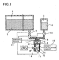
- FIG. 1 there is shown a toner density sensor to which the present invention is applied.
- the toner density sensor shown is incorporated in an ink jet head not shown of an image forming apparatus not shown such as, for example, a printer, a facsimile or a copying machine and includes a liquid developer tank 1 for accommodating liquid developer 2 to be used for development, a diluting liquid tank 3 for accommodating diluting liquid 4 formed of a base material of the liquid developer 2, and a mixing chamber 5 disposed outside and connected to the tanks 1 and 3 through a first valve 7 and a first pump 9, and a second valve 8 and a second pump 10, respectively.
- the first valve 7, second valve 8, first pump 9 and second pump 10 are controlled so as to be opened or closed by a control driver 17.
- a passage 13 of a circulation type is formed in part of the mixing chamber 5 with a third pump 11 interposed therein, and a transparent cell element 14 which allows an amount of transmission light through fluid which passes through the inside thereof to be measured is disposed in the passage 13. Further, a light emitting element 15 and a light receiving element 16 are disposed such that the transparent cell element 14 is positioned between them.
- the first valve 7 on the liquid developer tank 1 side is opened by the control driver 17 as seen in FIG. 2(a), and the liquid developer 2 is supplied by a predefined amount from the liquid developer tank 1 into the mixing chamber 5.
- the second valve 8 on the diluting liquid tank 3 side is opened by the control driver 17, and an amount of the diluting liquid 4 with which the dilution ratio of the liquid developer 2 to it is to be always kept fixed is supplied from the diluting liquid tank 3 into the mixing chamber 5.
- the first valve 7 and the second valve 8 are closed by the control driver 17 as seen from FIG. 2(b).
- the liquid developer 2 and diluting liquid 4 supplied in the mixing chamber 5 are agitated by an agitation member 12 disposed in the mixing chamber 5 to make liquid developer 6 for toner density detection.
- the liquid developer 6 for toner density detection agitated sufficiently is forcedly circulated between the mixing chamber 5 and the transparent cell element 14 by the third pump 11.
- an amount of transmission light through the liquid developer 6 for toner density detection in the transparent cell element 14 is measured by means of the light emitting element 15 and the light receiving element 16, and it is determined by a density calculation circuit 18 whether the liquid developer 2 in the liquid developer tank 1 has a density within an appropriate density range.
- the first valve 7 on the liquid developer tank 1 side is opened by the control driver as seen in FIG. 2(c), and the liquid developer 6 for toner density detection in the mixing chamber 5, in the transparent cell element 14 and the passage 13 between them is discharged to the liquid developer tank 1 side.
- the diluting liquid 4 is mixed at a certain fixed ratio into the liquid developer 2 in the mixing chamber 5 while the light path length of the transparent cell element 14 of such a degree that retention of toner or clogging of foreign articles does not occur is assured, and the liquid developer 6 for toner density detection diluted to such a density within a density range within which the transmission light amount can be measured is produced in the mixing chamber 5 and the transmission light amount through the liquid developer 6 for toner density detection is measured at the transparent cell element 14.
- the transmission light amount thus measured is compared with sample data of the density of the liquid developer 6 for toner density detection, which have been obtained in advance with the liquid developer 2 diluted similarly to a lower limit value and an upper limit value to the appropriate density range, by the density calculation circuit 18 to determine the density of the liquid developer 2.
- the amount of the liquid developer 6 for toner density detection is considerably smaller than the amount of the liquid developer 2.
- the mixing chamber 5 and the transparent cell element 14 are always filled with the diluting liquid 4.
- FIG. 3 there is shown another toner density sensor to which the present invention is applied.
- the toner density sensor of FIG. 3 is a modification to and different from the toner density sensor described hereinabove with reference to FIG. 1 in that the light emitting element 15 and the light receiving element 16 are covered completely with a transparent member 19 having a low surface energy property and disposed in an opposing relationship to each other with a certain fixed gap left therebetween in the mixing chamber 5.
- the light emitting element 15 and the transparent cell element 14 are immersed in the liquid developer 6 for toner density detection in the mixing chamber 5, and the liquid developer 6 for toner density detection is agitated by the agitation member 12 in the mixing chamber 5.
- the transmission light amount through the liquid developer 6 for toner density detection in the mixing chamber 5 is measured by the light emitting element 15 and the light receiving element 16, and it is determined by the density calculation circuit 18 whether the liquid developer 2 in the liquid developer tank 1 has a density within an appropriate density range.
- the toner density sensor is incorporated in an ink jet head of an image forming apparatus such as, for example, a printer, a facsimile or a copying machine, it may otherwise be incorporated in a developer of an electrophotographic image forming apparatus which additionally includes charging, exposure, transferring and fixing means.
- the toner density sensor is incorporated in a developer, the density of the liquid developer is controlled fixed based on a result of detection by the toner density sensor.
Landscapes
- Physics & Mathematics (AREA)
- General Physics & Mathematics (AREA)
- Wet Developing In Electrophotography (AREA)
- Ink Jet (AREA)
- Investigating Or Analysing Materials By Optical Means (AREA)
Applications Claiming Priority (2)
| Application Number | Priority Date | Filing Date | Title |
|---|---|---|---|
| JP10004611A JPH11198398A (ja) | 1998-01-13 | 1998-01-13 | トナー濃度センサーおよびそれを使用するインクジェットヘッドおよび現像器および画像形成装置 |
| JP461198 | 1998-01-13 |
Publications (3)
| Publication Number | Publication Date |
|---|---|
| EP0929009A2 true EP0929009A2 (fr) | 1999-07-14 |
| EP0929009A3 EP0929009A3 (fr) | 2001-03-28 |
| EP0929009B1 EP0929009B1 (fr) | 2004-10-27 |
Family
ID=11588858
Family Applications (1)
| Application Number | Title | Priority Date | Filing Date |
|---|---|---|---|
| EP99100494A Expired - Lifetime EP0929009B1 (fr) | 1998-01-13 | 1999-01-12 | Détecteur de densité de toner, tête à jet d'encre, unité de développement et appareil de formation d'images dans lequel ce détecteur est utilisé |
Country Status (4)
| Country | Link |
|---|---|
| US (1) | US6389244B1 (fr) |
| EP (1) | EP0929009B1 (fr) |
| JP (1) | JPH11198398A (fr) |
| DE (1) | DE69921377T2 (fr) |
Families Citing this family (7)
| Publication number | Priority date | Publication date | Assignee | Title |
|---|---|---|---|---|
| JP4230146B2 (ja) * | 1999-07-18 | 2009-02-25 | ヒューレット−パッカード・インデイゴ・ビー・ブイ | マルチプリンターシステムのための中央インク供給システム |
| US7643776B2 (en) * | 2004-05-25 | 2010-01-05 | Hewlett-Packard Development Company, L.P. | Ink building |
| JP4661217B2 (ja) * | 2004-12-28 | 2011-03-30 | コニカミノルタビジネステクノロジーズ株式会社 | 液体現像剤特性検出装置、液体現像装置及び画像形成装置 |
| JP2010085538A (ja) * | 2008-09-30 | 2010-04-15 | Konica Minolta Business Technologies Inc | 画像形成装置及び現像剤補給方法 |
| JP7010092B2 (ja) * | 2018-03-19 | 2022-01-26 | 株式会社リコー | 液体を吐出する装置 |
| CN109895508B (zh) * | 2019-04-24 | 2021-02-05 | 珠海杨杋科技有限公司 | 一种打印机墨盒 |
| CN110376860B (zh) * | 2019-06-25 | 2022-03-11 | 恒科科技产业有限公司 | 一种基于黑白打印机用的墨粉压衬平刀滑削的内胆墨盒 |
Family Cites Families (14)
| Publication number | Priority date | Publication date | Assignee | Title |
|---|---|---|---|---|
| US3299787A (en) * | 1962-11-27 | 1967-01-24 | Harris Intertype Corp | Electrophotographic micro-copy printer |
| JPS51453B1 (fr) * | 1968-11-05 | 1976-01-08 | ||
| JPS49114430A (fr) | 1973-02-28 | 1974-10-31 | ||
| JPS551573B2 (fr) | 1974-01-28 | 1980-01-16 | ||
| JPS533348A (en) * | 1976-06-30 | 1978-01-13 | Konishiroku Photo Ind Co Ltd | Process and device for controlling toner density of developer liquid |
| JPS5680473A (en) | 1979-12-06 | 1981-07-01 | Ricoh Co Ltd | Ink jet recording device |
| JPS58111069A (ja) * | 1981-12-24 | 1983-07-01 | Canon Inc | 現像液の濃度制御装置 |
| EP0171902B1 (fr) * | 1984-06-29 | 1990-09-05 | Matsushita Graphic Communication Systems, Inc. | Dispositif pour contrôler la concentration d'un système de développement liquide |
| JPS6461253A (en) | 1987-09-02 | 1989-03-08 | Ricoh Kk | Ink jet printer |
| JPH04278966A (ja) | 1991-03-07 | 1992-10-05 | Ricoh Co Ltd | 湿式電子写真複写機 |
| US5369476A (en) * | 1992-01-28 | 1994-11-29 | Cactus | Toner control system and method for electrographic printing |
| US5319421A (en) | 1992-09-22 | 1994-06-07 | Xerox Corporation | Toner concentration sensing with self calibration |
| JP3269321B2 (ja) | 1995-04-14 | 2002-03-25 | 東洋インキ製造株式会社 | 記録液の分散性評価方法 |
| JPH0915982A (ja) * | 1995-06-28 | 1997-01-17 | Minolta Co Ltd | 液物性モニター装置 |
-
1998
- 1998-01-13 JP JP10004611A patent/JPH11198398A/ja active Pending
-
1999
- 1999-01-12 EP EP99100494A patent/EP0929009B1/fr not_active Expired - Lifetime
- 1999-01-12 DE DE69921377T patent/DE69921377T2/de not_active Expired - Fee Related
- 1999-01-13 US US09/229,305 patent/US6389244B1/en not_active Expired - Fee Related
Also Published As
| Publication number | Publication date |
|---|---|
| US6389244B1 (en) | 2002-05-14 |
| EP0929009A3 (fr) | 2001-03-28 |
| DE69921377T2 (de) | 2005-03-17 |
| JPH11198398A (ja) | 1999-07-27 |
| EP0929009B1 (fr) | 2004-10-27 |
| DE69921377D1 (de) | 2004-12-02 |
Similar Documents
| Publication | Publication Date | Title |
|---|---|---|
| KR100370533B1 (ko) | 화상 형성 장치 | |
| US6389244B1 (en) | Toner density sensor, and ink jet head, developing unit and image forming apparatus in which toner density sensor is used | |
| US7650100B2 (en) | Development apparatus, image forming apparatus, and developer transfer method | |
| US6278850B1 (en) | Device of measuring concentration of developer liquid for liquid-type printer | |
| US6289184B1 (en) | Apparatus for measuring concentration of developer of liquid printer | |
| US7212752B2 (en) | Image forming apparatus and a developing apparatus having a unit for determining a mixture ratio of two types of magnetic toner based on magnetic permeability and amount | |
| JPH0990733A (ja) | 画像形成装置のトナー供給装置 | |
| US5897240A (en) | Concentration measuring device of electrographic printer | |
| JP7367452B2 (ja) | 画像形成装置および画像形成装置の制御方法 | |
| KR100457507B1 (ko) | 인쇄기의 현상액 농도 조절장치 | |
| JP3987167B2 (ja) | 画像形成装置 | |
| KR100243155B1 (ko) | 인쇄기의 현상액 농도 및 대전량 측정장치 | |
| US7664414B2 (en) | Liquid developing device and wet image forming device | |
| KR100297786B1 (ko) | 습식 인쇄기의 현상액 농도 측정장치 | |
| KR100490389B1 (ko) | 인쇄기의현상액농도측정장치 | |
| JP2003066708A (ja) | 現像装置および画像形成装置 | |
| CA2073444A1 (fr) | Dispositifs de developpement automatique de materiaux photographiques | |
| JPH1195538A (ja) | 現像装置 | |
| JPH03107873A (ja) | 感光体劣化検知装置 | |
| KR100243236B1 (ko) | 잉크교반방법 | |
| US20110058837A1 (en) | Detecting colorants within carrier liquid | |
| JPH02179664A (ja) | 現像装置 | |
| JPH04152248A (ja) | 湿式カラー画像形成装置における濃度検知装置 | |
| JP2006038479A (ja) | 透過率測定方法及び画像形成装置 | |
| Gibson et al. | Control of liquid Electrophoretic toner supplies |
Legal Events
| Date | Code | Title | Description |
|---|---|---|---|
| PUAI | Public reference made under article 153(3) epc to a published international application that has entered the european phase |
Free format text: ORIGINAL CODE: 0009012 |
|
| AK | Designated contracting states |
Kind code of ref document: A2 Designated state(s): DE FR GB |
|
| AX | Request for extension of the european patent |
Free format text: AL;LT;LV;MK;RO;SI |
|
| PUAL | Search report despatched |
Free format text: ORIGINAL CODE: 0009013 |
|
| AK | Designated contracting states |
Kind code of ref document: A3 Designated state(s): AT BE CH CY DE DK ES FI FR GB GR IE IT LI LU MC NL PT SE |
|
| AX | Request for extension of the european patent |
Free format text: AL;LT;LV;MK;RO;SI |
|
| 17P | Request for examination filed |
Effective date: 20010221 |
|
| AKX | Designation fees paid |
Free format text: DE FR GB |
|
| 17Q | First examination report despatched |
Effective date: 20030429 |
|
| GRAP | Despatch of communication of intention to grant a patent |
Free format text: ORIGINAL CODE: EPIDOSNIGR1 |
|
| GRAS | Grant fee paid |
Free format text: ORIGINAL CODE: EPIDOSNIGR3 |
|
| GRAA | (expected) grant |
Free format text: ORIGINAL CODE: 0009210 |
|
| AK | Designated contracting states |
Kind code of ref document: B1 Designated state(s): DE FR GB |
|
| PG25 | Lapsed in a contracting state [announced via postgrant information from national office to epo] |
Ref country code: FR Free format text: LAPSE BECAUSE OF FAILURE TO SUBMIT A TRANSLATION OF THE DESCRIPTION OR TO PAY THE FEE WITHIN THE PRESCRIBED TIME-LIMIT Effective date: 20041027 |
|
| REG | Reference to a national code |
Ref country code: GB Ref legal event code: FG4D |
|
| REF | Corresponds to: |
Ref document number: 69921377 Country of ref document: DE Date of ref document: 20041202 Kind code of ref document: P |
|
| PLBE | No opposition filed within time limit |
Free format text: ORIGINAL CODE: 0009261 |
|
| STAA | Information on the status of an ep patent application or granted ep patent |
Free format text: STATUS: NO OPPOSITION FILED WITHIN TIME LIMIT |
|
| ET | Fr: translation filed | ||
| 26N | No opposition filed |
Effective date: 20050728 |
|
| EN | Fr: translation not filed | ||
| REG | Reference to a national code |
Ref country code: FR Ref legal event code: EERR Free format text: CORRECTION DE BOPI 05/51 - BREVETS EUROPEENS DONT LA TRADUCTION N A PAS ETE REMISE A L INPI. IL Y A LIEU DE SUPPRIMER : LA MENTION DE LA NON REMISE PUBLIEE PAR ERREUR. |
|
| PGFP | Annual fee paid to national office [announced via postgrant information from national office to epo] |
Ref country code: DE Payment date: 20070104 Year of fee payment: 9 |
|
| PGFP | Annual fee paid to national office [announced via postgrant information from national office to epo] |
Ref country code: GB Payment date: 20070110 Year of fee payment: 9 |
|
| GBPC | Gb: european patent ceased through non-payment of renewal fee |
Effective date: 20080112 |
|
| PG25 | Lapsed in a contracting state [announced via postgrant information from national office to epo] |
Ref country code: DE Free format text: LAPSE BECAUSE OF NON-PAYMENT OF DUE FEES Effective date: 20080801 |
|
| PG25 | Lapsed in a contracting state [announced via postgrant information from national office to epo] |
Ref country code: GB Free format text: LAPSE BECAUSE OF NON-PAYMENT OF DUE FEES Effective date: 20080112 |
|
| REG | Reference to a national code |
Ref country code: FR Ref legal event code: EERR Free format text: CORRECTION DE BOPI 05/51 - 3.2. |
|
| PGFP | Annual fee paid to national office [announced via postgrant information from national office to epo] |
Ref country code: FR Payment date: 20080101 Year of fee payment: 9 |
|
| REG | Reference to a national code |
Ref country code: FR Ref legal event code: ST Effective date: 20111223 |
|
| PG25 | Lapsed in a contracting state [announced via postgrant information from national office to epo] |
Ref country code: FR Free format text: LAPSE BECAUSE OF FAILURE TO SUBMIT A TRANSLATION OF THE DESCRIPTION OR TO PAY THE FEE WITHIN THE PRESCRIBED TIME-LIMIT Effective date: 20080131 |