EP0929160A2 - Gerät und Verfahren für das Verringern der lokalen Störung im Teilnehmerschleife-Nachrichtenübertragungssystem - Google Patents
Gerät und Verfahren für das Verringern der lokalen Störung im Teilnehmerschleife-Nachrichtenübertragungssystem Download PDFInfo
- Publication number
- EP0929160A2 EP0929160A2 EP99300032A EP99300032A EP0929160A2 EP 0929160 A2 EP0929160 A2 EP 0929160A2 EP 99300032 A EP99300032 A EP 99300032A EP 99300032 A EP99300032 A EP 99300032A EP 0929160 A2 EP0929160 A2 EP 0929160A2
- Authority
- EP
- European Patent Office
- Prior art keywords
- echo
- communications channel
- transmit signal
- signal
- frequency band
- Prior art date
- Legal status (The legal status is an assumption and is not a legal conclusion. Google has not performed a legal analysis and makes no representation as to the accuracy of the status listed.)
- Granted
Links
Images


Classifications
-
- H—ELECTRICITY
- H04—ELECTRIC COMMUNICATION TECHNIQUE
- H04B—TRANSMISSION
- H04B3/00—Line transmission systems
- H04B3/02—Details
- H04B3/20—Reducing echo effects or singing; Opening or closing transmitting path; Conditioning for transmission in one direction or the other
- H04B3/23—Reducing echo effects or singing; Opening or closing transmitting path; Conditioning for transmission in one direction or the other using a replica of transmitted signal in the time domain, e.g. echo cancellers
Definitions
- the invention relates to communication systems, and more particularly, to an apparatus and method for reducing interference in a communication system.
- a twisted pair telephone line may have a bandwidth of several MHZ.
- the voice band frequency was the only bandwidth used with these lines because the equipment at the telephone company would only pass the voice band.
- modern telephone equipment can support higher transmission rates.
- end user telephone and data communication equipment typically use the same voice band.
- the signals are greatly attenuated especially when transmitted over distances up to several thousand meters.
- any transmitter such as a modem and its associated circuitry, transmits the signal at a much higher power than is usual to account for the signal attenuation.
- a frequency range above a voice frequency band for some transmission, such as data transmission, it is possible to simultaneously use the telephone for normal voice communication.
- a receiver's analog-to-digital converter may need a very large dynamic range so that the composite received signal (the received signal including the echo) does not saturate the analog-to-digital converter. It is also important to sample the desired signal with enough resolution to meet the required signal-to-noise ratio. This requirement is difficult to achieve in practice.
- a voltage scaler is operatively connected to the transmitter to generate the scaled replica of the transmit signal which, in turn, is fed to an inverting input of an amplifier to cancel the unwanted echo based on the transmitted signal.
- this type of device and method are limited because it was assumed that half of the power was transmitted to the telephone line, while half the power was reflected back into the receiver as unwanted interference in the entire frequency band.
- This system also anticipated a fixed line impedance (e.g., 110 Ohms) to obtain cancellation of the unwanted echo signal before it reached the analog-to-digital converter of the receiver.
- the local echo may have a different amplitude than that produced by the scaler configured for a fixed line impedance.
- the replicated echo cancellation signal may be ineffective due to amplitude and phase differences between the unwanted transmitter signal forming the echo and the replicated signal. This is because the scaler only tries to match the resistive component and ignores the inductive and capacitive components of the line impedance. To overcome this in the past has meant designing complex analog filters and high-dynamic range A/D's as mentioned previously.
- the apparatus comprises a transmitter for generating a transmit signal to the communications channel in a frequency band outside a voice frequency band.
- a scaler is connected to the transmitter and generates a scaled replica of the transmit signal based upon a scale control signal.
- a receiver receives signals from the communications channel either within or outside the voice frequency band and is susceptible to undesired local echo from the transmit signal. The receiver is connected to the scaler and reduces the undesired local echo by subtraction of the scaled replica of the transmit signal.
- An echo reducing means senses the received signal power and generates the scaled control signal based upon the received signal power thereby reducing the undesired local echo.
- the echo reducing means preferably comprises a test means for testing the communications channel by inputting a predetermined test signal to the transmitter when or before the received signal power is being sent from the far end.
- the echo reducing means further comprises power minimizing means for setting the scaled control signal responsive to the minimum received signal power during testing of the communications channel.
- the receiver comprises an amplifier having one input connected to the communications channel, and a second input connected to the scaler.
- the amplifier acts as a subtractor because it subtracts or cancels the unwanted transmit signal with a scaled replica of it.
- An analog-to-digital converter (ADC) is connected to an output of the amplifier.
- the echo reducing means comprises an encoder connected between an output of the ADC and a scaler.
- the scaler comprises voltage scaling means for generating a scaled voltage replica signal.
- the scaler comprises a resistor ladder for setting the scaled control signal.
- the resistor ladder comprises a plurality of tuning resistors, and a respective switch connected thereto. The switches are connected to and responsive to the encoder.
- the apparatus comprises a transmitter for generating a transmit signal to the communications channel in a frequency band outside a voice frequency band.
- Echo reducing means generates a scaled replica of the transmit signal, which is phase and amplitude adjusted therewith.
- the echo reducing means also comprises channel characterization means for characterizing the communications channel.
- the receiver receives signals from the communications channel either outside or in the voice frequency band and is susceptible to undesired local echo from the transmit signal.
- the receiver is connected to the echo reducing means and reduces the undesired local echo by subtraction of the amplitude and phased adjusted replica of the transmit signal.
- the echo reducing means comprises a processor for creating a model of the undesired local echo.
- This model consists of a digital filter, possibly implemented in a DSP, so that the transfer function of the cancellor path (i.e., H(z), D/A, filtering and gain blocks) exactly or approximately matches the normal transmitted local echo path in terms of both amplitude and phase.
- the channel characterization means further comprises means for generating a test signal.
- the echo cancellation means further comprises memory means for storing a plurality of models relating to the respective different characterizations of the communications channel.
- the memory means can comprise a ROM or RAM or non-volatile RAM.
- the apparatus comprises an antialiasing filter.
- the receiver comprises an amplifier that acts as a subtractor, and has one input connected to the communications channel and a second input connected to the echo reducing means.
- the echo reducing means further comprises a digital-to-analog converter (DAC) connected to the second input of the amplifier.
- An analog-to-digital converter (ADC) can be connected to the output of the amplifier.
- a low pass filter can be connected between the amplifier and the ADC.
- a method aspect of the invention allows communication over a communications channel with reduced undesired local echo.
- the method comprises the steps of generating the transmit signal to the communications channel in a frequency band outside the voice frequency band.
- the method further comprises generating a scaled replica of the transmit signal based upon a scaled control signal.
- the method further comprises reducing the undesired local echo by subtracting the scaled replica of the transmit signal from the received signals.
- the method further comprises sensing received signal power and generating the scaled control signal based upon the received signal power to thereby reduce the undesired local echo.
- the method further comprises the step of reducing echo by testing the communications channel by inputting a predetermined test signal for transmission when the unwanted received signal power is being sensed.
- the method further comprises the step of reducing echo by setting the scaled control signal responsive to sensing a minimum received signal power during testing of the communications channel.
- the method comprises the steps of generating a transmit signal to the communications channel in a frequency band above a voice frequency band.
- the method comprises generating a scaled replica of the transmit signal, phase synchronized therewith, and characterizing the communications channel.
- the method further comprises receiving signals from the communications channel within or outside the voice frequency band and being susceptible to undesired local echo from the transmit signal, and while reducing the undesired local echo by subtraction of the scaled and phase synchronized replica of the transmit signal.
- FIG. 1 is a schematic block diagram of a prior art communication apparatus using a voltage scaler to reduce echo.
- FIG. 2 is a schematic block circuit diagram of an apparatus of the present invention for reducing local echo.
- FIG. 3 is a more detailed schematic block circuit diagram of a portion of the apparatus as shown in FIG. 2.
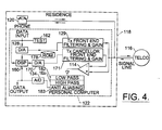
- FIG. 4 is a schematic block circuit diagram of another embodiment of the apparatus of the present invention where a transfer function of the cancellor path is generated to match the normal transmitted local echo path in terms of both amplitude and phase.
- the present invention permits the reduction of local echo in a communication system, particularly an asymmetric digital subscriber loop communication system.
- Asymmetric digital subscriber loop communication systems are becoming increasingly more popular.
- An example of such a system is disclosed in U.S. Patent No. 5,461,616 to Suzuki, disclosing an interactive television system, such as video-on-demand, network game, and home shopping systems using a switching network.
- the system uses an existing telephone line to form a two-way transmission of the audio signal at 3.4 kHz as in the case of a normal telephone system. Images are transmitted at 1.5 Mbps from an exchange to a subscriber. A control signal is transmitted which requests the desired image signal at 16 kbps from the subscriber to the exchange. This subscriber line is referred to as an asymmetric digital subscriber line.
- ADSL digital subscriber loop communications
- VDSL very high frequency digital subscriber loop communication systems
- FIG. 1 illustrates a prior art improvement over these methods outlined above by an apparatus which uses a voltage scaler 12 for producing a scaled replica of the transmit signal.
- This scaled replica is input into an operational amplifier 14 , together with the received signal from the communications channel connected to a switch of a telephone company (Telco) 16 .
- a residence is defined by dotted line 18 , and includes a telephone 20 and personal computer (indicated by dotted lines at 22 ) having a modem.
- the telephone 20 operates on a standard 300 to 3,300 hertz bandwidth, while the computer 22 includes the modem for generating and transmitting a transmit signal over a communications channel in a frequency range above the voice frequency band. This frequency can be over a broad spectrum.
- the higher frequency communications channel would be appropriate for Internet access.
- a low bandwidth could be used for transmitting signals, such as a keystroke command, while a high bandwidth could be used for downloading pictures, graphics and other data from an Internet provider.
- data is input into a digital-to-analog converter 28 , which receives the data input from the personal computer 22 , and generates a transmit signal into the communications channel. Any data modulation in this modern modem is most likely to occur before digital-to-analog conversion.
- This transmit signal typically has a greater power than a signal received from the Telco 16 to account for attenuation problems, using the higher frequencies above the voice frequency band. Generally the power of the transmit signal can vary as known to those skilled in the art. This greater power produces a local echo, such as when the signal traverses from the two wires in a residential circuit to the common four wires, causing an impedance change. Thus, the received signal includes an unwanted local echo.
- the voltage scaler 12 receives part of the transmit signal and inputs it into one input of the amplifier 14 , together with the signals received from the communications channel within or outside the voice frequency band, which includes the unwanted transmit composite signal forming the local echo.
- the output of the amplifier 14 is the received signal from the signal line with some cancelled echo.
- the receiver includes an analog-to-digital converter 34 , generating the desired output. Data demodulation will most likely occur after analog-to-digital conversion.
- This system has a drawback because line impedance can vary by ⁇ 20%. In the structure of FIG. 1, various assumptions can be made, such as a line impedance (Zo) that equals 110 ⁇ ⁇ 20%.
- Vr should equal 0.5Vt. This is assuming an 80% mismatch with the assumption that there is no perfect line impedance matching. Assuming there is an 80% mismatch, it is still possible to obtain a reduction of transmitted power of 18 db.
- the power cancellation of the unwanted transmit signal forming the local echo can be improved when the voltage scaler provides the exact amplitude replica of the transmit signal forming the local echo.
- the voltage scaler 112 is responsive to a scale control signal as generated by echo reducing means in the form of an encoder 140 , which generates the scale control signal to the voltage scaler 112 based upon the received signal power from the analog-to-digital converter 134 , thereby reducing echo.
- the apparatus is part of a personal computer 122 , communicating via modem with Telco 116 .
- the apparatus in accordance with the present invention, does not have to be part of a personal computer.
- the residence 118 includes a phone 120 as standard.
- Power sensing means 142 includes circuitry for measuring the received power of the signal and in conjunction with the encoder sets the scale control signal responsive to sensing a minimum received signal power during testing of the communications channel.
- Test means 144 in the form of a testing circuit is operable for characterizing the line impedance and is operable by inputting a predetermined test signal to the transmitter when or before the received signal power is being sensed. It is desirable to "test” the line by sending test signals and listening for them in the receiver band, and then optimizing the cancellation before "real" received data is received. Several test signals may be required before optimal cancellation can be achieved.
- the voltage scaler 112 determines the amplitude of the transmit signal that is fed through the cancelling operational amplifier 114 , which is a summing amplifier.
- the voltage scaler 112 could be established assuming that the line impedance was about 110 ohms.
- the power sensing means 142 would measure the power of the signal from the ADC 134 and with the encoder 140 , adjust the voltage scaler 112 accordingly so that the local echo could be reduced by subtraction of the scaled replica of the transmit signal. Further adjustments could be made until the optimum voltage scaling was achieved.
- the voltage scaling could be achieved by several different methods, including one scheme having a resistor ladder 150 , as shown in FIG. 3, with a tap point at the central portion of the resistor ladder 150 for setting the scale control signal.
- the resistor ladder 150 comprises a plurality of tuning resistors 152 with respective switches 154 in the form of transistors, labeled in the P and D series.
- the resistor value is adaptably adjusted so that the voltage is scaled to the amplitude.
- the unwanted transmit signal at the top is called Vt and comes into the resistor ladder 150 , where it is emitted as "scaled Vt.”
- the scaled Vt will be a certain ratio of the original Vt depending on how many of the transistor switches are open or closed.
- Vt as scaled can be made as accurate as required by making the resistor ladder "deeper.”
- the Vt as scaled can be defined by the following equation:
- FIGS. 2 and 3 have illustrated the apparatus and the method in accordance with one aspect of the present invention, where the unwanted local echo ia subtracted by the use of a scaled replica of the local echo from the received signal. It should be noted that the apparatus would not have an effect on phase delays and frequency distortions on the transmitted signal.
- FIG. 4 illustrates a schematic block diagram of the apparatus in another aspect of the present invention, where the subtracted signal has similar characteristics as the unwanted receive signal in terms of both phase and amplitude.
- the phone 120 is included within the residence 118 , as is the personal computer 122 .
- the echo reducing means generates a scaled replica of the transmit signal phase synchronized with the transmit signal.
- channel characterization means 162 characterizes the communications channel by generating a test signal to the transmitter and its digital-to-analog converter (DAC).
- DAC digital-to-analog converter
- a digital signal processor 160 receives the test signals and data input generated such as from the home computer 122 , as well as the data output from the analog-to-digital converter 134 .
- the digital signal processor 160 processes the data output and the test signal, and creates a digital model of the local echo such as generated by the test signal, based on the amplitude and frequency, which are then converted by a digital-to-analog converter 170 to an analog signal and input into the amplifier 114 to act as a cancellation signal. Typically, data modulation will occur before digital-to-analog conversion. Additionally, as illustrated, the signal can pass through transmitter cancellor front end filtering 171 .
- the digital signal processor and associated processing circuitry could use standard algorithms or other associated methodology known to those skilled in the art, and creates a digital model for the transfer function of the local echo path H(Z). This model can be created before the digital conversation is begun with the transmission of signals.
- the channel characterization means 162 characterizes the line impedance by sending test signals to measure how effectively the cancellation is working.
- the optimum H(Z) would be that which causes the transfer function of the cancellor path (i.e., H(z), D/A 170 , filter and gain block 171 to the input of the amplifier 114 ) to match the transfer function of the local echo path (i.e., from the transmitter digital-to-analog converter 128 through a front end filtering and gain circuit 129 to the input of the amplifier 114 ).
- the model of the path from the transmitter digital-to-analog converter to the input of the operational amplifier can be developed so that the computational overhead for the various coefficients can be calculated only once before the actual transmission of data.
- the plurality of different digital models relating to respective echoes characterized by different line impedances can also be stored.
- the storage can be in ROM 178 or in RAM or in non-volatile RAM.
- a low-pass filter 182 and high pass filter 182a could also be included as illustrated to further filter any cancelled signal before it reaches the analog-to-digital converter 134 . This could be beneficial because the noise bandwidth of the signal would otherwise be large and cause convergence problems in the practical implementation of the H(Z).
- the specification of this filter could be merged with an antialias filter 183 in order to reduce the cost of implementing the whole structure. It is also possible that updating can occur during transmission using a parameter such as a bit error rate as a flag for recharacterization of the line.
- the digital-to-analog converter 170 in the cancellor path can be clocked at a different rate and have a different resolution (i.e., the number of quantization levels) than the transmit digital-to-analog converter 128 , as it could improve the transfer function matching.
- One major advantage of the present invention is that the components as described can be fabricated on one semiconductor substrate, thus reducing costs. Without this invention, the design would require complex analog filtering and an analog-to-digital converter with very high dynamic range. Both of these are difficult to design, especially on one integrated chip. This invention simplifies the requirements of both the analog filtering and the analog-to-digital converter so that it can be more easily implemented on a single integrated chip and so making the entire solution smaller and dissipate less power and be more cost effective. Another advantage could be to allow recharacterization to compensate for component and other variations in this system due to temperature, aging, manufacturing tolerances or changes in line impedance.
Landscapes
- Engineering & Computer Science (AREA)
- Computer Networks & Wireless Communication (AREA)
- Signal Processing (AREA)
- Cable Transmission Systems, Equalization Of Radio And Reduction Of Echo (AREA)
- Telephonic Communication Services (AREA)
Applications Claiming Priority (2)
| Application Number | Priority Date | Filing Date | Title |
|---|---|---|---|
| US09/003,380 US6181791B1 (en) | 1998-01-06 | 1998-01-06 | Apparatus and method for reducing local interference in subscriber loop communication system |
| US3380 | 1998-01-06 |
Publications (3)
| Publication Number | Publication Date |
|---|---|
| EP0929160A2 true EP0929160A2 (de) | 1999-07-14 |
| EP0929160A3 EP0929160A3 (de) | 2004-02-04 |
| EP0929160B1 EP0929160B1 (de) | 2007-02-28 |
Family
ID=21705601
Family Applications (1)
| Application Number | Title | Priority Date | Filing Date |
|---|---|---|---|
| EP99300032A Expired - Lifetime EP0929160B1 (de) | 1998-01-06 | 1999-01-05 | Gerät und Verfahren für das Verringern der lokalen Störung im Teilnehmerschleife-Nachrichtenübertragungssystem |
Country Status (3)
| Country | Link |
|---|---|
| US (1) | US6181791B1 (de) |
| EP (1) | EP0929160B1 (de) |
| DE (1) | DE69935268D1 (de) |
Cited By (2)
| Publication number | Priority date | Publication date | Assignee | Title |
|---|---|---|---|---|
| DE19933485B4 (de) * | 1999-07-16 | 2004-05-13 | Infineon Technologies Ag | Leitungsabschlußeinrichtung für eine Telefon-Teilnehmeranschlußleitung |
| EP1069700A3 (de) * | 1999-07-13 | 2004-06-23 | STMicroelectronics, Inc. | Echounterdrückung für ein ADSL-Modem |
Families Citing this family (7)
| Publication number | Priority date | Publication date | Assignee | Title |
|---|---|---|---|---|
| US6377683B1 (en) * | 1998-05-29 | 2002-04-23 | 3Com Corporation | Low complexity frequency domain echo canceller for DMT transceivers |
| US6542604B1 (en) * | 1998-08-31 | 2003-04-01 | Infineon Technologies Ag | Scaled impedance replica for echo attenuation in digital transmission systems |
| US6993127B2 (en) * | 2000-03-31 | 2006-01-31 | Spirent Communications Of Rockville, Inc. | Method and apparatus for gradual application of a hitless monitoring access to a communications circuit employing a guided transmission media |
| US6879625B1 (en) * | 2000-05-22 | 2005-04-12 | Globespanvirata, Inc | System and method for providing cancellation of interference in a repeater configuration with remote loop powering |
| US6631178B1 (en) * | 2001-01-12 | 2003-10-07 | Adtran, Inc. | System and method for transmitting data over loaded and unloaded twisted pairs |
| US7176823B2 (en) * | 2002-11-19 | 2007-02-13 | Stmicroelectronics, Inc. | Gigabit ethernet line driver and hybrid architecture |
| US20190215139A1 (en) * | 2018-01-08 | 2019-07-11 | Maxlinear, Inc. | Digital CW Cancellation for High QAM For Point-to-Point FDD Systems |
Family Cites Families (14)
| Publication number | Priority date | Publication date | Assignee | Title |
|---|---|---|---|---|
| US4707824A (en) * | 1983-12-15 | 1987-11-17 | Nec Corporation | Method and apparatus for cancelling echo |
| JPH0616592B2 (ja) * | 1985-12-23 | 1994-03-02 | 富士通株式会社 | Fdmモデム |
| US4987569A (en) * | 1989-04-05 | 1991-01-22 | Codex Corporation | Fast training echo canceller |
| US5162762A (en) * | 1991-03-25 | 1992-11-10 | At&T Bell Laboratories | Phase-lock loop with adaptive scaling element |
| JP2794999B2 (ja) * | 1991-08-14 | 1998-09-10 | 国際電信電話株式会社 | エコーキャンセル方式 |
| IT1254819B (it) * | 1992-02-24 | 1995-10-11 | Sits Soc It Telecom Siemens | Procedimento e dispositivo per la cancellazione numerica adattativa dell'eco generato in collegamenti telefonici non stazionari |
| US5307405A (en) * | 1992-09-25 | 1994-04-26 | Qualcomm Incorporated | Network echo canceller |
| US5596604A (en) | 1993-08-17 | 1997-01-21 | Amati Communications Corporation | Multicarrier modulation transmission system with variable delay |
| JPH0774846A (ja) | 1993-09-01 | 1995-03-17 | Fujitsu Ltd | 非対称ディジタル加入者線制御方式 |
| US5623513A (en) | 1993-12-13 | 1997-04-22 | Amati Communications Corporation | Mitigating clipping and quantization effects in digital transmission systems |
| EP0677938A1 (de) | 1994-04-14 | 1995-10-18 | ALCATEL BELL Naamloze Vennootschap | Signalkoppler |
| US5625646A (en) * | 1995-06-26 | 1997-04-29 | Motorola, Inc. | Method, device, DSP and modem for efficient echo canceler phase roll tracking |
| DE69634027T2 (de) * | 1995-08-14 | 2005-12-22 | Nippon Telegraph And Telephone Corp. | Akustischer Teilband-Echokompensator |
| CN1111973C (zh) * | 1996-08-01 | 2003-06-18 | 北方电讯网络有限公司 | 改进了的数字蜂窝应用的回波消除器 |
-
1998
- 1998-01-06 US US09/003,380 patent/US6181791B1/en not_active Expired - Lifetime
-
1999
- 1999-01-05 DE DE69935268T patent/DE69935268D1/de not_active Expired - Lifetime
- 1999-01-05 EP EP99300032A patent/EP0929160B1/de not_active Expired - Lifetime
Cited By (3)
| Publication number | Priority date | Publication date | Assignee | Title |
|---|---|---|---|---|
| EP1069700A3 (de) * | 1999-07-13 | 2004-06-23 | STMicroelectronics, Inc. | Echounterdrückung für ein ADSL-Modem |
| DE19933485B4 (de) * | 1999-07-16 | 2004-05-13 | Infineon Technologies Ag | Leitungsabschlußeinrichtung für eine Telefon-Teilnehmeranschlußleitung |
| US7164708B1 (en) | 1999-07-16 | 2007-01-16 | Infineon Technologies Ag | Line termination device for a telephone subscriber line |
Also Published As
| Publication number | Publication date |
|---|---|
| US6181791B1 (en) | 2001-01-30 |
| DE69935268D1 (de) | 2007-04-12 |
| EP0929160A3 (de) | 2004-02-04 |
| EP0929160B1 (de) | 2007-02-28 |
Similar Documents
| Publication | Publication Date | Title |
|---|---|---|
| US5790658A (en) | High performance echo canceller for high speed modem | |
| US4636586A (en) | Speakerphone with adaptive cancellation of room echoes | |
| JP2620285B2 (ja) | 電話機のハンドフリー機能を実現するための装置 | |
| US5896452A (en) | Multi-channel echo canceler and method using convolution of two training signals | |
| US5659581A (en) | Modem receiver pre-emphasis | |
| JPS6171728A (ja) | デイジタル・エコー・キヤンセラー | |
| JP2002335195A (ja) | 時間領域エコー消去処理においてトーンの存在に起因する誤集束を回避するためのシステムおよび方法 | |
| US6580696B1 (en) | Multi-adaptation for a voice packet based | |
| JPH0480569B2 (de) | ||
| JP3877882B2 (ja) | 適応フィルタ | |
| US20020101982A1 (en) | Line echo canceller scalable to multiple voice channels/ports | |
| JPS59225626A (ja) | デ−タ伝送装置用エコ−キヤンセラ装置 | |
| JPH09130316A (ja) | セルラ・モデム用のエコー・キャンセラ利得トラッカ | |
| JP2591764B2 (ja) | アダプティブタイムディスクリートフィルタ | |
| US6965578B1 (en) | Echo canceling method and apparatus for digital data communication system | |
| EP0929160B1 (de) | Gerät und Verfahren für das Verringern der lokalen Störung im Teilnehmerschleife-Nachrichtenübertragungssystem | |
| US7194037B1 (en) | Active replica transformer hybrid | |
| JPS6167329A (ja) | 双方向適応音声周波数中継器 | |
| US20030123650A1 (en) | Simple adaptive hybrid circuit | |
| WO2000025434A1 (en) | Arrangement and method for interference cancelling | |
| US7298711B1 (en) | Echo cancellation in a communication device | |
| US7046798B2 (en) | System and method for subliminal time domain duplexing | |
| JPH07273691A (ja) | 電気通信システムにおけるディジタルエコーキャンセラーの適応制御のための方法 | |
| JPS6222290B2 (de) | ||
| JP3244416B2 (ja) | エコーキャンセラ |
Legal Events
| Date | Code | Title | Description |
|---|---|---|---|
| PUAI | Public reference made under article 153(3) epc to a published international application that has entered the european phase |
Free format text: ORIGINAL CODE: 0009012 |
|
| AK | Designated contracting states |
Kind code of ref document: A2 Designated state(s): AT BE CH CY DE DK ES FI FR GB GR IE IT LI LU MC NL PT SE |
|
| AX | Request for extension of the european patent |
Free format text: AL;LT;LV;MK;RO;SI |
|
| RIC1 | Information provided on ipc code assigned before grant |
Ipc: 7H 04L 5/06 B Ipc: 7H 04M 11/06 B Ipc: 7H 04B 1/58 B Ipc: 7H 04B 3/03 B Ipc: 7H 04B 3/23 A |
|
| PUAL | Search report despatched |
Free format text: ORIGINAL CODE: 0009013 |
|
| AK | Designated contracting states |
Kind code of ref document: A3 Designated state(s): AT BE CH CY DE DK ES FI FR GB GR IE IT LI LU MC NL PT SE |
|
| AX | Request for extension of the european patent |
Extension state: AL LT LV MK RO SI |
|
| 17P | Request for examination filed |
Effective date: 20040729 |
|
| AKX | Designation fees paid |
Designated state(s): DE FR GB IT |
|
| 17Q | First examination report despatched |
Effective date: 20050520 |
|
| GRAP | Despatch of communication of intention to grant a patent |
Free format text: ORIGINAL CODE: EPIDOSNIGR1 |
|
| GRAS | Grant fee paid |
Free format text: ORIGINAL CODE: EPIDOSNIGR3 |
|
| GRAA | (expected) grant |
Free format text: ORIGINAL CODE: 0009210 |
|
| AK | Designated contracting states |
Kind code of ref document: B1 Designated state(s): DE FR GB IT |
|
| REG | Reference to a national code |
Ref country code: GB Ref legal event code: FG4D |
|
| REF | Corresponds to: |
Ref document number: 69935268 Country of ref document: DE Date of ref document: 20070412 Kind code of ref document: P |
|
| ET | Fr: translation filed | ||
| PLBE | No opposition filed within time limit |
Free format text: ORIGINAL CODE: 0009261 |
|
| STAA | Information on the status of an ep patent application or granted ep patent |
Free format text: STATUS: NO OPPOSITION FILED WITHIN TIME LIMIT |
|
| PG25 | Lapsed in a contracting state [announced via postgrant information from national office to epo] |
Ref country code: DE Free format text: LAPSE BECAUSE OF FAILURE TO SUBMIT A TRANSLATION OF THE DESCRIPTION OR TO PAY THE FEE WITHIN THE PRESCRIBED TIME-LIMIT Effective date: 20070530 |
|
| 26N | No opposition filed |
Effective date: 20071129 |
|
| PG25 | Lapsed in a contracting state [announced via postgrant information from national office to epo] |
Ref country code: IT Free format text: LAPSE BECAUSE OF FAILURE TO SUBMIT A TRANSLATION OF THE DESCRIPTION OR TO PAY THE FEE WITHIN THE PRESCRIBED TIME-LIMIT Effective date: 20070228 |
|
| GBPC | Gb: european patent ceased through non-payment of renewal fee |
Effective date: 20080105 |
|
| REG | Reference to a national code |
Ref country code: FR Ref legal event code: ST Effective date: 20081029 |
|
| PG25 | Lapsed in a contracting state [announced via postgrant information from national office to epo] |
Ref country code: GB Free format text: LAPSE BECAUSE OF NON-PAYMENT OF DUE FEES Effective date: 20080105 |
|
| PG25 | Lapsed in a contracting state [announced via postgrant information from national office to epo] |
Ref country code: FR Free format text: LAPSE BECAUSE OF NON-PAYMENT OF DUE FEES Effective date: 20080131 |