EP0929176B1 - Erkennung von Aufgabetrennblättern in einem Dokumentabtastgerät - Google Patents
Erkennung von Aufgabetrennblättern in einem Dokumentabtastgerät Download PDFInfo
- Publication number
- EP0929176B1 EP0929176B1 EP99100276A EP99100276A EP0929176B1 EP 0929176 B1 EP0929176 B1 EP 0929176B1 EP 99100276 A EP99100276 A EP 99100276A EP 99100276 A EP99100276 A EP 99100276A EP 0929176 B1 EP0929176 B1 EP 0929176B1
- Authority
- EP
- European Patent Office
- Prior art keywords
- model
- image
- alignment marker
- scanned
- job
- Prior art date
- Legal status (The legal status is an assumption and is not a legal conclusion. Google has not performed a legal analysis and makes no representation as to the accuracy of the status listed.)
- Expired - Lifetime
Links
- 239000003550 marker Substances 0.000 claims description 33
- 238000000034 method Methods 0.000 claims description 17
- 238000012545 processing Methods 0.000 claims description 9
- 238000012549 training Methods 0.000 claims description 9
- 238000012795 verification Methods 0.000 description 8
- 238000001514 detection method Methods 0.000 description 6
- 230000008569 process Effects 0.000 description 4
- 230000000717 retained effect Effects 0.000 description 3
- PXFBZOLANLWPMH-UHFFFAOYSA-N 16-Epiaffinine Natural products C1C(C2=CC=CC=C2N2)=C2C(=O)CC2C(=CC)CN(C)C1C2CO PXFBZOLANLWPMH-UHFFFAOYSA-N 0.000 description 2
- 230000005540 biological transmission Effects 0.000 description 2
- 230000008859 change Effects 0.000 description 2
- 238000004891 communication Methods 0.000 description 2
- 238000013461 design Methods 0.000 description 2
- 238000010586 diagram Methods 0.000 description 2
- 230000001419 dependent effect Effects 0.000 description 1
- 230000000694 effects Effects 0.000 description 1
- 238000002474 experimental method Methods 0.000 description 1
- 230000006870 function Effects 0.000 description 1
- 238000003384 imaging method Methods 0.000 description 1
- 230000007246 mechanism Effects 0.000 description 1
- 238000000926 separation method Methods 0.000 description 1
Images


Classifications
-
- H—ELECTRICITY
- H04—ELECTRIC COMMUNICATION TECHNIQUE
- H04N—PICTORIAL COMMUNICATION, e.g. TELEVISION
- H04N1/00—Scanning, transmission or reproduction of documents or the like, e.g. facsimile transmission; Details thereof
- H04N1/00795—Reading arrangements
- H04N1/00798—Circuits or arrangements for the control thereof, e.g. using a programmed control device or according to a measured quantity
- H04N1/00801—Circuits or arrangements for the control thereof, e.g. using a programmed control device or according to a measured quantity according to characteristics of the original
- H04N1/00803—Presence or absence of information
-
- H—ELECTRICITY
- H04—ELECTRIC COMMUNICATION TECHNIQUE
- H04N—PICTORIAL COMMUNICATION, e.g. TELEVISION
- H04N1/00—Scanning, transmission or reproduction of documents or the like, e.g. facsimile transmission; Details thereof
- H04N1/00795—Reading arrangements
Definitions
- This invention is generally related to the recognition of job separator pages and, more particularly, to a system and method for recognizing job separator pages that precede actual jobs in a scanning job such as in document handlers of a copier or scanner.
- US-A 4,352,012 discloses a header sheet for use with an automatic image communication transmission system, having regularly spaced hash marks around the border to identify the sheet as a header. Additional markings are in the border to identify the leading edge of the sheet relative to the scan raster of the system, and areas to designate sender and addressee stations by the location of markings relative to the position of the scan raster.
- US-A 5.051,779 discloses an image processing system that specifies input image information on the basis of existence of a special mark or patterns printed on a job control sheet. Selected one of various image processing is executed in accordance with the existence of the special marks or patterns to thereby obtain output image information.
- Each of the special marks or patterns are line drawings, each drawn so as to have a certain low correlative angle to longitudinal and transverse directions of an image provided with the special mark or patterns.
- US-A 5.243.381 discloses a method provided for printing a job, represented by a set of electronic pages, with a job reference sheet in a printing system, the printing system having a printer and a scanner adapted to both convert the job into the set of electronic pages and decode machine readable code.
- the method includes the steps of storing the set of electronic pages in a memory section and assigning a unique job identifier to the stored job for indicating a location of the stored job in the memory section.
- the method further includes the steps of printing the job reference sheet so that the unique job identifier is designated on the job reference sheet in machine readable code and scanning the job reference sheet for reading the machine readable code to retrieve the set of electronic pages from the memory section for printing with the printer.
- This object is achieved by providing a system for recognizing a job separator page on a scanning device according to claim 1 and a method for recognizing job separator pages within an image processing system according to claim 6.
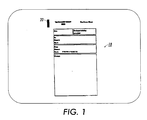
- a "model" is a scanned image of a separator page suitably superimposed with an alignment marker.
- the model can be either fixed in a machine before shipping for machine-designed separator pages (say printed by a document center system to be re-used at the time of scanning), or could be learned during a training mode after deployment at the customer site, where a user designates a particular document of his/her choice to be a separator page for subsequent jobs. The latter is useful in an office environment where users can design their own logo-based separator pages.
- the input to the model generation stage is a scanned bitmap of the separator page. For purposes of reliable detection, the bitmap is assumed to be scanned at a high resolution (400 dpi) during the training stage. The model generation stage then puts a digital alignment marker on the original document.
- the example alignment marker 20 is a dark rectangular region. Such a region is salient, can be easily detected, and is less likely to be confused with other content in the document. Moreover, the use of rectangular region leads to a reliable computation of pose parameters, providing at least 4 features.
- the alignment marker is placed at the first available place on the bitmap that can accommodate such a marker. Usually, such a place can be found at the top left corner of the page.
- a dark rectangular region of size 42 x 10 (in the normalized image of size 512 x 352) was chosen in experiments.
- the model page 10 is stored in its reduced resolution form (chosen was 512 x 512) for fast matching during job sheet recognition.
- the four extremes of the alignment marker in the normalized image are noted as part of the model description of the separator page (denoted by ( P 1 , P 2 , P 3 , P 4 ) in the following formulas).
- the full resolution image is, however, used for reproduction (by printing) for subsequent jobs as a separator page.
- the detection of alignment marker involves the detection of the parallelogram corresponding to the marker using the following operations. Connected components of dark pixels are formed. Regions with a pixel count that is within a scale change bound are retained. An increase or decrease of size by a factor of 10 is chosen as the threshold. This accounts for copying jobs requiring scaling.
- the polygon area is computed after finding the boundary pixels of the region.
- the pixel-count is simply the number of black pixels in the region.
- the above step retained all filled regions.
- L 2 T ( ( A - C ⁇ ) 2 + B 2 ) - A - C , - ( ( A - C ⁇ ) 2 + B 2 ) + A - C
- the coordinates of the point of intersection of these orthogonal axes give the bounding oriented rectangle around the region. Let it be denoted by ( R 1 , R 2 , R 3 , R 4 ). Using the bounding oriented rectangle coordinates, 4 external points on the region's contour that are closest to R 1 R 2 , R 3 , R 4 , respectively, are derived. Such external points are convexities along the region's contour as obtained by a line-segment approximation. Let the resulting quadrilateral be denoted by ( S 1 , S 2 , S 3 , S 4 ).
- the region detected is a parallelogram if: Area of S 1 ⁇ S 2 ⁇ S 3 ⁇ S 4 - Pixel - count R ⁇ ⁇ where ⁇ is a suitably chosen threshold.
- ⁇ is a suitably chosen threshold.
- the equivalence is detected within a small error threshold for deviations from a parallelogram under noise.
- the verification step determines an "on" pixel on the model to be matched if it projects near an on-pixel in the image in a neighborhood (say 5 x 5 pixel neighborhood).
- the ratio of matched pixels to the total number of on-pixels constitutes a verification score D ( M,I ).
- the same process is repeated from image to model by projecting the image onto the model using the inverse affine parameters and the ratio D ( I,M ) is similarly computed.
- the projection is done both ways to achieve robustness against false positives, particular, when a document has a dark rectangular regions, and is fairly busy in terms of the number of pixels so that a pixel-match from model to image would be achieved but not image to model.
- the verification is said to succeed if: min D M ⁇ I , D I ⁇ M ⁇ d Where d is some suitably chosen threshold.
- Figure 1 illustrates a separator page 10 with a marker 20.
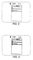
- Figure 2 shows a skewed version of the same page as may appear on a document handler (the skew being a slight clockwise rotation).
- the skewed page has been recognized as a separator page by projecting the model page of Figure 1 onto the image page of Figure 2.
- Figures 4 and 5 shows the recognition of the separator page in a inverted pose as can happen when the page is scanned in the wrong orientation.
- Figure 4 illustrates the job separator page of Figure 1 with large skew of about 180+ degree rotation.
- the model page ( Figure 1) is projected onto the image of Figure 4 which is then recognized as a job separator page.
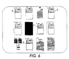
- Figure 6 shows the accuracy of separator page detection in the midst of other pages.
- a set of twelve pages are processed with four being detected as separator pages using the invention.
- These four recognized pages are marked as A, B, C, and D in Figure 6, as further shown by projecting the model onto the respective pages.
- These images have been scanned at different resolution, ranging from 200dpi to 400dpi. Note that some of the images not recognized have the same content as the model page but lack the alignment marker, indicating the accuracy of recognition.
- a system 100 for recognizing a job separator page on a scanning device 14, would comprising a detection controller module 101 for receiving scanned input from the scanning device 111 and providing the controlled input to system components for verification 102 of a job separator page.
- the controller 101 accesses a memory module 103 which stores models used to compare against the scanned input. Once the model is projected onto he input, the verification module 102 verifies a match and the existence of a job page separator. This information can then be used by a printer 112 to process to job based on job parameters. Or the job documents may be stored subsequently in a database/repository 113.
- the documents can be distributed over the network 114 via email or other internet communications.
- the training option described above is provided by a training module 104 in cooperation with the memory module 103 and controller 101.
- Arbitrary images can be turned into a separator page models by digital placement of at least one alignment marker on said arbitrary image and storing said arbitrary image with said at least one alignment marker in said memory 103.
- the system as illustrated in Figure 7 and describe above can all be implemented with a microprocessor programmed to control and operate as said means for receiving scanned input from a scanning device, means for detecting an alignment marker on a scanned image, means for computing pose parameters for said alignment marker by matching said alignment marker of said scanned image to a model, means for storing at least one modeL and means for verifying said scanned image as a job separator page by projecting said model onto said scanned image using said pose parameters.
- the Detection controller, verification and training modules would be combined into microprocessor functions and the memory module would provide the models and program information to the microprocessor.
Landscapes
- Engineering & Computer Science (AREA)
- Multimedia (AREA)
- Signal Processing (AREA)
- Facsimiles In General (AREA)
- Facsimile Scanning Arrangements (AREA)
- Image Analysis (AREA)
- Editing Of Facsimile Originals (AREA)
- Image Input (AREA)
Claims (7)
- Ein System zur Erkennung einer Auftragstrennseite (10) auf einer Abtasteinrichtung (111) umfassend:a) eine Einrichtung (101) zum Empfangen einer abgetasteten Eingabe von einer Abtasteinrichtung;
gekennzeichnet durch:b) eine Einrichtung zur Detektion einer Ausrichtmarkierung (20) auf einem abgetasteten Bild;c) eine Einrichtung zur Berechnung von Stellungsparametem für die Ausrichtmarkierung (20) durch Abgleichen der Ausrichtmarkierung des abgetasteten Bildes mit einem Modell;d) eine Einrichtung (103) zum Speichern von mindestens einem Modell;e) eine Einrichtung (102) zur Verifikation des abgetasteten Bildes als eine Auftragstrennseite (10) durch Projizieren des Modells auf das abgetastete Bild unter Verwendung der Stellungsparameter; undf) eine Einrichtung zur Steuerung der Empfangseinrichtung, der Detektionseinrichtung, der Berechnungseinrichtung, der Speichereinrichtung und der Verfikationseinrichtung. - Das System gemäß Anspruch 1, weiterhin umfassend ein Trainingsmodul (104) zum Trainieren des Systems mit einer Vielzahl von Modellen, wobei ein beliebiges Bild in eine Trennseite und Modell gewandelt werden kann durch digitales Anordnen von mindestens einer Ausrichtmarkierung (20) auf dem beliebigen Bild und Speichern des beliebigen Bildes mit der mindestens einen Ausrichtmarkierung in der Einrichtung (103) zum Speichern von mindestens einem Modell.
- Das System gemäß Anspruch 2, wobei ein Mikroprozessor programmiert ist, um die Einrichtung (101) zum Empfangen einer abgetasteten Eingabe von einer Abtasteinrichtung, die Einrichtung zur Detektion einer Ausrichtmarkierung auf einem abgetasteten Bild, die Einrichtung zur Berechnung von Stellungsparametem für die Ausrichtmarkierung durch Abgleichen der Ausrichtmarkierung des abgetasteten Bildes mit einem Modell, die Einrichtung (103) zum Speichern von mindestens einem Modell, und die Einrichtung (102) zur Verifikation des abgetasteten Bildes als eine Auftragstrennseite durch Projizieren des Modells auf das abgetastete Bild unter Verwendung der Stellungsparameter.
- Das System gemäß Anspruch 3, wobei der Mikroprozessor weiterhin programmiert ist, um das Trainingsmodul (104) zu steuern und zu betreiben.
- Das System gemäß Ansprüchen 1 bis 3, wobei das System das Modell verwendet, um die Umstände der Trennseite (10) unter dem Satz von abzutastenden Dokumenten zu erkennen durch Berücksichtigung der Unterschiede in der Abtastauflösung, Verkippung, Seitentranslation und Rauschen.
- Verfahren zur Erkennung von Auftragstrennseiten innerhalb eines Bildverarbeitungssytems, umfassend:a) Empfangen einer abgetasteten Eingabe von einer Abtasteinrichtung;
gekennzeichnet durchb) Detektieren einer Ausrichtmarkierung auf einem abgetasteten Bild, das als Teil der abgetasteten Eingabe empfangen wird;c) Berechnen von Stellungsparametem für die Ausrichtmarkierung durch Abgleich der Ausrichtmarkierung des abgetasteten Bildes mit einem Modell; undd) Verifizieren des abgetasteten Bildes als eine Auftragstrennseite durch Projizieren des Modells auf das abgetastete Bild unter Verwendung der Stellungsparameter und Auffinden eines Abgleichs. - Das Verfahren gemäß Anspruch 6, weiterhin umfassend das Trainieren des Systems mit einer Vielzahl von Modellen, wobei ein beliebiges Bild in eine Trennseite und Modell gewandelt werden kann durch digitales Anordnen von mindestens einer Ausrichtmarkierung auf dem beliebigen Bild und Abspeichern des beliebigen Bildes mit der mindestens einen Ausrichtmarkierung für die Verwendung während der Erkennung.
Applications Claiming Priority (2)
| Application Number | Priority Date | Filing Date | Title |
|---|---|---|---|
| US09/004,637 US5978620A (en) | 1998-01-08 | 1998-01-08 | Recognizing job separator pages in a document scanning device |
| US4637 | 1998-01-08 |
Publications (3)
| Publication Number | Publication Date |
|---|---|
| EP0929176A2 EP0929176A2 (de) | 1999-07-14 |
| EP0929176A3 EP0929176A3 (de) | 2000-10-25 |
| EP0929176B1 true EP0929176B1 (de) | 2007-08-08 |
Family
ID=21711740
Family Applications (1)
| Application Number | Title | Priority Date | Filing Date |
|---|---|---|---|
| EP99100276A Expired - Lifetime EP0929176B1 (de) | 1998-01-08 | 1999-01-08 | Erkennung von Aufgabetrennblättern in einem Dokumentabtastgerät |
Country Status (4)
| Country | Link |
|---|---|
| US (1) | US5978620A (de) |
| EP (1) | EP0929176B1 (de) |
| JP (1) | JP2000036897A (de) |
| DE (1) | DE69936743T2 (de) |
Families Citing this family (7)
| Publication number | Priority date | Publication date | Assignee | Title |
|---|---|---|---|---|
| US6621930B1 (en) * | 2000-08-09 | 2003-09-16 | Elron Software, Inc. | Automatic categorization of documents based on textual content |
| US20050006480A1 (en) * | 2003-07-07 | 2005-01-13 | Srikrishna Talluri | Method and apparatus for management of a document generation process |
| JP4929643B2 (ja) * | 2005-08-08 | 2012-05-09 | コニカミノルタビジネステクノロジーズ株式会社 | 画像位置合わせ装置及びプログラム |
| JP2009049571A (ja) | 2007-08-15 | 2009-03-05 | Oki Data Corp | 画像読取装置 |
| WO2009060975A1 (ja) * | 2007-11-08 | 2009-05-14 | Nec Corporation | 特徴点配置照合装置及び画像照合装置、その方法及びプログラム |
| US9491328B2 (en) | 2015-02-28 | 2016-11-08 | Xerox Corporation | System and method for setting output plex format using automatic page detection |
| FR3050045B1 (fr) * | 2016-04-08 | 2022-03-04 | Sas Sages Informatique | Procede et systeme de separation de documents lors d'une numerisation par lot |
Family Cites Families (18)
| Publication number | Priority date | Publication date | Assignee | Title |
|---|---|---|---|---|
| US4352012A (en) * | 1980-02-22 | 1982-09-28 | Verderber Joseph A | Header sheet for image communications system |
| JPS59163250A (ja) * | 1983-03-08 | 1984-09-14 | Ricoh Co Ltd | 原稿供給装置 |
| JPS60136760A (ja) * | 1983-12-26 | 1985-07-20 | Minolta Camera Co Ltd | 複写機 |
| US4757348A (en) * | 1986-11-17 | 1988-07-12 | Xerox Corporation | High speed electronic reprographic/printing machine |
| JP2673298B2 (ja) * | 1987-12-17 | 1997-11-05 | 三菱電機株式会社 | セルフテスト機能付半導体集積回路 |
| US4970554A (en) * | 1988-10-24 | 1990-11-13 | Xerox Corporation | Job processing system for high speed electronic copying/printing machines |
| US4987447A (en) * | 1989-09-18 | 1991-01-22 | Eastman Kodak Company | Control sheet generation for copiers and printers |
| US5051779A (en) * | 1990-10-10 | 1991-09-24 | Fuji Xerox Co., Ltd. | Job control sheet for image processing system |
| US5247371A (en) * | 1990-10-10 | 1993-09-21 | Fuji Xerox Co., Ltd. | Image processing system using job control sheets with attributes |
| US5161037A (en) * | 1990-10-10 | 1992-11-03 | Fuji Xerox Corporation, Ltd. | Image processing system and method for processing documents in accordance with a job control sheet |
| JP3133400B2 (ja) * | 1991-07-15 | 2001-02-05 | キヤノン株式会社 | 複写装置 |
| JPH05289456A (ja) * | 1992-04-10 | 1993-11-05 | Fuji Xerox Co Ltd | 画像処理装置 |
| US5438430A (en) * | 1992-09-25 | 1995-08-01 | Xerox Corporation | Paper user interface for image manipulations such as cut and paste |
| US5243381A (en) * | 1993-01-04 | 1993-09-07 | Xerox Corporation | Method for compiling multiple jobs with job reference sheets |
| IE69673B1 (en) * | 1994-04-06 | 1996-10-02 | Offset Studios Ltd | An image processing method |
| JP3088608B2 (ja) * | 1994-06-07 | 2000-09-18 | シャープ株式会社 | 画像形成装置 |
| JP3534331B2 (ja) * | 1994-08-09 | 2004-06-07 | ゼロックス コーポレイション | ネットワークインタフェースを使用して多種のローカル及びリモートソースから多セグメント印刷ジョブを構築する方法 |
| US5619649A (en) * | 1995-06-12 | 1997-04-08 | Xerox Corporation | Network printing system for programming a print job by selecting a job ticket identifier associated with remotely stored predefined document processing control instructions |
-
1998
- 1998-01-08 US US09/004,637 patent/US5978620A/en not_active Expired - Lifetime
-
1999
- 1999-01-04 JP JP11000020A patent/JP2000036897A/ja active Pending
- 1999-01-08 DE DE69936743T patent/DE69936743T2/de not_active Expired - Lifetime
- 1999-01-08 EP EP99100276A patent/EP0929176B1/de not_active Expired - Lifetime
Non-Patent Citations (1)
| Title |
|---|
| None * |
Also Published As
| Publication number | Publication date |
|---|---|
| EP0929176A2 (de) | 1999-07-14 |
| DE69936743D1 (de) | 2007-09-20 |
| EP0929176A3 (de) | 2000-10-25 |
| JP2000036897A (ja) | 2000-02-02 |
| DE69936743T2 (de) | 2007-12-06 |
| US5978620A (en) | 1999-11-02 |
Similar Documents
| Publication | Publication Date | Title |
|---|---|---|
| EP0764308B1 (de) | Anlage und verfahren zur automatischen seitenerfassung und detektion von formularen | |
| JPH06124358A (ja) | 用紙上のマークを検出する方法 | |
| US20090252437A1 (en) | Image Skew Detection Apparatus And Methods | |
| US20100103481A1 (en) | Image processing apparatus, image forming apparatus, image reading apparatus, image processing method, and recording medium | |
| JPH11203480A (ja) | 画像検出方法及びシステム | |
| US20070002375A1 (en) | Segmenting and aligning a plurality of cards in a multi-card image | |
| US5796877A (en) | Method and apparatus for automatically fitting an input image to the size of the output document | |
| US11140286B2 (en) | System and method for alignment of scan documents | |
| US20040066526A1 (en) | Inspection device and image forming apparatus | |
| JP6620038B2 (ja) | 画像処理装置及び画像処理プログラム | |
| EP0929176B1 (de) | Erkennung von Aufgabetrennblättern in einem Dokumentabtastgerät | |
| US6771842B1 (en) | Document image skew detection method | |
| EP0961472A2 (de) | Bildverarbeitungsgerät und -verfahren und rechnerlesbarer Speicher | |
| US5649028A (en) | Connect-the-dots drawing production device | |
| US11343406B2 (en) | Image reading apparatus, image reading system, image reading method, and non-transitory computer-readable storage medium storing program | |
| JP3671682B2 (ja) | 画像認識装置 | |
| US7085012B2 (en) | Method for an image forming device to process a media, and an image forming device arranged in accordance with the same method | |
| EP1229494A2 (de) | Verfahren, Vorrichtung und Programmspeichermedium zur Bestimmung des Umrisses eines gescannten Bildes | |
| JPH08305791A (ja) | 画像認識装置及び制御シート | |
| JPH11213089A (ja) | 画像処理装置及びその方法 | |
| JPH08315067A (ja) | 文字読取装置 | |
| JP2001218008A (ja) | 画像処理装置、画像処理方法および記憶媒体 | |
| JP6617420B2 (ja) | 画像処理装置および画像形成装置 | |
| JPH09214648A (ja) | 画像処理装置 | |
| JP2001030580A (ja) | 画像処理装置、印刷制御方法、及び記憶媒体 |
Legal Events
| Date | Code | Title | Description |
|---|---|---|---|
| PUAI | Public reference made under article 153(3) epc to a published international application that has entered the european phase |
Free format text: ORIGINAL CODE: 0009012 |
|
| AK | Designated contracting states |
Kind code of ref document: A2 Designated state(s): DE FR GB |
|
| AX | Request for extension of the european patent |
Free format text: AL;LT;LV;MK;RO;SI |
|
| PUAL | Search report despatched |
Free format text: ORIGINAL CODE: 0009013 |
|
| AK | Designated contracting states |
Kind code of ref document: A3 Designated state(s): AT BE CH CY DE DK ES FI FR GB GR IE IT LI LU MC NL PT SE |
|
| AX | Request for extension of the european patent |
Free format text: AL;LT;LV;MK;RO;SI |
|
| 17P | Request for examination filed |
Effective date: 20010221 |
|
| AKX | Designation fees paid |
Free format text: DE FR GB |
|
| GRAP | Despatch of communication of intention to grant a patent |
Free format text: ORIGINAL CODE: EPIDOSNIGR1 |
|
| GRAS | Grant fee paid |
Free format text: ORIGINAL CODE: EPIDOSNIGR3 |
|
| GRAA | (expected) grant |
Free format text: ORIGINAL CODE: 0009210 |
|
| AK | Designated contracting states |
Kind code of ref document: B1 Designated state(s): DE FR GB |
|
| REG | Reference to a national code |
Ref country code: GB Ref legal event code: FG4D |
|
| REF | Corresponds to: |
Ref document number: 69936743 Country of ref document: DE Date of ref document: 20070920 Kind code of ref document: P |
|
| ET | Fr: translation filed | ||
| PLBE | No opposition filed within time limit |
Free format text: ORIGINAL CODE: 0009261 |
|
| STAA | Information on the status of an ep patent application or granted ep patent |
Free format text: STATUS: NO OPPOSITION FILED WITHIN TIME LIMIT |
|
| 26N | No opposition filed |
Effective date: 20080509 |
|
| REG | Reference to a national code |
Ref country code: FR Ref legal event code: PLFP Year of fee payment: 18 |
|
| PGFP | Annual fee paid to national office [announced via postgrant information from national office to epo] |
Ref country code: GB Payment date: 20151224 Year of fee payment: 18 |
|
| PGFP | Annual fee paid to national office [announced via postgrant information from national office to epo] |
Ref country code: FR Payment date: 20151222 Year of fee payment: 18 |
|
| PGFP | Annual fee paid to national office [announced via postgrant information from national office to epo] |
Ref country code: DE Payment date: 20151217 Year of fee payment: 18 |
|
| REG | Reference to a national code |
Ref country code: DE Ref legal event code: R119 Ref document number: 69936743 Country of ref document: DE |
|
| GBPC | Gb: european patent ceased through non-payment of renewal fee |
Effective date: 20170108 |
|
| REG | Reference to a national code |
Ref country code: FR Ref legal event code: ST Effective date: 20170929 |
|
| PG25 | Lapsed in a contracting state [announced via postgrant information from national office to epo] |
Ref country code: FR Free format text: LAPSE BECAUSE OF NON-PAYMENT OF DUE FEES Effective date: 20170131 |
|
| PG25 | Lapsed in a contracting state [announced via postgrant information from national office to epo] |
Ref country code: DE Free format text: LAPSE BECAUSE OF NON-PAYMENT OF DUE FEES Effective date: 20170801 Ref country code: GB Free format text: LAPSE BECAUSE OF NON-PAYMENT OF DUE FEES Effective date: 20170108 |