EP0929178B1 - Ausrichtungsfehler reduzierende Spiegelhalterung in einem Abtastwagen - Google Patents
Ausrichtungsfehler reduzierende Spiegelhalterung in einem Abtastwagen Download PDFInfo
- Publication number
- EP0929178B1 EP0929178B1 EP99300117A EP99300117A EP0929178B1 EP 0929178 B1 EP0929178 B1 EP 0929178B1 EP 99300117 A EP99300117 A EP 99300117A EP 99300117 A EP99300117 A EP 99300117A EP 0929178 B1 EP0929178 B1 EP 0929178B1
- Authority
- EP
- European Patent Office
- Prior art keywords
- mirrors
- spacer plates
- housing
- scanner carriage
- mirror
- Prior art date
- Legal status (The legal status is an assumption and is not a legal conclusion. Google has not performed a legal analysis and makes no representation as to the accuracy of the status listed.)
- Expired - Lifetime
Links
Images

Classifications
-
- H—ELECTRICITY
- H04—ELECTRIC COMMUNICATION TECHNIQUE
- H04N—PICTORIAL COMMUNICATION, e.g. TELEVISION
- H04N1/00—Scanning, transmission or reproduction of documents or the like, e.g. facsimile transmission; Details thereof
- H04N1/024—Details of scanning heads ; Means for illuminating the original
- H04N1/028—Details of scanning heads ; Means for illuminating the original for picture information pick-up
- H04N1/02815—Means for illuminating the original, not specific to a particular type of pick-up head
- H04N1/02845—Means for illuminating the original, not specific to a particular type of pick-up head using an elongated light source, e.g. tubular lamp, LED array
- H04N1/0285—Means for illuminating the original, not specific to a particular type of pick-up head using an elongated light source, e.g. tubular lamp, LED array in combination with at least one reflector which is in fixed relation to the light source
-
- H—ELECTRICITY
- H04—ELECTRIC COMMUNICATION TECHNIQUE
- H04N—PICTORIAL COMMUNICATION, e.g. TELEVISION
- H04N1/00—Scanning, transmission or reproduction of documents or the like, e.g. facsimile transmission; Details thereof
- H04N1/024—Details of scanning heads ; Means for illuminating the original
- H04N1/028—Details of scanning heads ; Means for illuminating the original for picture information pick-up
- H04N1/02815—Means for illuminating the original, not specific to a particular type of pick-up head
- H04N1/02845—Means for illuminating the original, not specific to a particular type of pick-up head using an elongated light source, e.g. tubular lamp, LED array
- H04N1/0287—Means for illuminating the original, not specific to a particular type of pick-up head using an elongated light source, e.g. tubular lamp, LED array using a tubular lamp or a combination of such lamps
-
- H—ELECTRICITY
- H04—ELECTRIC COMMUNICATION TECHNIQUE
- H04N—PICTORIAL COMMUNICATION, e.g. TELEVISION
- H04N1/00—Scanning, transmission or reproduction of documents or the like, e.g. facsimile transmission; Details thereof
- H04N1/024—Details of scanning heads ; Means for illuminating the original
- H04N1/028—Details of scanning heads ; Means for illuminating the original for picture information pick-up
- H04N1/02815—Means for illuminating the original, not specific to a particular type of pick-up head
- H04N1/02885—Means for compensating spatially uneven illumination, e.g. an aperture arrangement
-
- H—ELECTRICITY
- H04—ELECTRIC COMMUNICATION TECHNIQUE
- H04N—PICTORIAL COMMUNICATION, e.g. TELEVISION
- H04N1/00—Scanning, transmission or reproduction of documents or the like, e.g. facsimile transmission; Details thereof
- H04N1/024—Details of scanning heads ; Means for illuminating the original
- H04N1/028—Details of scanning heads ; Means for illuminating the original for picture information pick-up
- H04N1/03—Details of scanning heads ; Means for illuminating the original for picture information pick-up with photodetectors arranged in a substantially linear array
-
- H—ELECTRICITY
- H04—ELECTRIC COMMUNICATION TECHNIQUE
- H04N—PICTORIAL COMMUNICATION, e.g. TELEVISION
- H04N1/00—Scanning, transmission or reproduction of documents or the like, e.g. facsimile transmission; Details thereof
- H04N1/04—Scanning arrangements, i.e. arrangements for the displacement of active reading or reproducing elements relative to the original or reproducing medium, or vice versa
- H04N1/10—Scanning arrangements, i.e. arrangements for the displacement of active reading or reproducing elements relative to the original or reproducing medium, or vice versa using flat picture-bearing surfaces
- H04N1/1013—Scanning arrangements, i.e. arrangements for the displacement of active reading or reproducing elements relative to the original or reproducing medium, or vice versa using flat picture-bearing surfaces with sub-scanning by translatory movement of at least a part of the main-scanning components
- H04N1/1017—Scanning arrangements, i.e. arrangements for the displacement of active reading or reproducing elements relative to the original or reproducing medium, or vice versa using flat picture-bearing surfaces with sub-scanning by translatory movement of at least a part of the main-scanning components the main-scanning components remaining positionally invariant with respect to one another in the sub-scanning direction
-
- H—ELECTRICITY
- H04—ELECTRIC COMMUNICATION TECHNIQUE
- H04N—PICTORIAL COMMUNICATION, e.g. TELEVISION
- H04N1/00—Scanning, transmission or reproduction of documents or the like, e.g. facsimile transmission; Details thereof
- H04N1/04—Scanning arrangements, i.e. arrangements for the displacement of active reading or reproducing elements relative to the original or reproducing medium, or vice versa
- H04N1/10—Scanning arrangements, i.e. arrangements for the displacement of active reading or reproducing elements relative to the original or reproducing medium, or vice versa using flat picture-bearing surfaces
- H04N1/1013—Scanning arrangements, i.e. arrangements for the displacement of active reading or reproducing elements relative to the original or reproducing medium, or vice versa using flat picture-bearing surfaces with sub-scanning by translatory movement of at least a part of the main-scanning components
- H04N1/1039—Movement of the main scanning components
- H04N1/1043—Movement of the main scanning components of a sensor array
-
- H—ELECTRICITY
- H04—ELECTRIC COMMUNICATION TECHNIQUE
- H04N—PICTORIAL COMMUNICATION, e.g. TELEVISION
- H04N1/00—Scanning, transmission or reproduction of documents or the like, e.g. facsimile transmission; Details thereof
- H04N1/04—Scanning arrangements, i.e. arrangements for the displacement of active reading or reproducing elements relative to the original or reproducing medium, or vice versa
- H04N1/10—Scanning arrangements, i.e. arrangements for the displacement of active reading or reproducing elements relative to the original or reproducing medium, or vice versa using flat picture-bearing surfaces
- H04N1/1013—Scanning arrangements, i.e. arrangements for the displacement of active reading or reproducing elements relative to the original or reproducing medium, or vice versa using flat picture-bearing surfaces with sub-scanning by translatory movement of at least a part of the main-scanning components
- H04N1/1039—Movement of the main scanning components
- H04N1/1048—Movement of the main scanning components of a lens or lens arrangement
-
- H—ELECTRICITY
- H04—ELECTRIC COMMUNICATION TECHNIQUE
- H04N—PICTORIAL COMMUNICATION, e.g. TELEVISION
- H04N1/00—Scanning, transmission or reproduction of documents or the like, e.g. facsimile transmission; Details thereof
- H04N1/04—Scanning arrangements, i.e. arrangements for the displacement of active reading or reproducing elements relative to the original or reproducing medium, or vice versa
- H04N1/10—Scanning arrangements, i.e. arrangements for the displacement of active reading or reproducing elements relative to the original or reproducing medium, or vice versa using flat picture-bearing surfaces
- H04N1/1013—Scanning arrangements, i.e. arrangements for the displacement of active reading or reproducing elements relative to the original or reproducing medium, or vice versa using flat picture-bearing surfaces with sub-scanning by translatory movement of at least a part of the main-scanning components
- H04N1/1039—Movement of the main scanning components
- H04N1/1052—Movement of the main scanning components of a mirror
-
- H—ELECTRICITY
- H04—ELECTRIC COMMUNICATION TECHNIQUE
- H04N—PICTORIAL COMMUNICATION, e.g. TELEVISION
- H04N1/00—Scanning, transmission or reproduction of documents or the like, e.g. facsimile transmission; Details thereof
- H04N1/04—Scanning arrangements, i.e. arrangements for the displacement of active reading or reproducing elements relative to the original or reproducing medium, or vice versa
- H04N1/19—Scanning arrangements, i.e. arrangements for the displacement of active reading or reproducing elements relative to the original or reproducing medium, or vice versa using multi-element arrays
- H04N1/191—Scanning arrangements, i.e. arrangements for the displacement of active reading or reproducing elements relative to the original or reproducing medium, or vice versa using multi-element arrays the array comprising a one-dimensional [1D] array
- H04N1/192—Simultaneously or substantially simultaneously scanning picture elements on one main scanning line
- H04N1/193—Simultaneously or substantially simultaneously scanning picture elements on one main scanning line using electrically scanned linear arrays, e.g. linear CCD arrays
-
- H—ELECTRICITY
- H04—ELECTRIC COMMUNICATION TECHNIQUE
- H04N—PICTORIAL COMMUNICATION, e.g. TELEVISION
- H04N2201/00—Indexing scheme relating to scanning, transmission or reproduction of documents or the like, and to details thereof
- H04N2201/024—Indexing scheme relating to scanning, transmission or reproduction of documents or the like, and to details thereof deleted
- H04N2201/02452—Arrangements for mounting or supporting elements within a scanning head
- H04N2201/02454—Element mounted or supported
- H04N2201/0246—Mirror, reflecting element or beam splitter
-
- H—ELECTRICITY
- H04—ELECTRIC COMMUNICATION TECHNIQUE
- H04N—PICTORIAL COMMUNICATION, e.g. TELEVISION
- H04N2201/00—Indexing scheme relating to scanning, transmission or reproduction of documents or the like, and to details thereof
- H04N2201/024—Indexing scheme relating to scanning, transmission or reproduction of documents or the like, and to details thereof deleted
- H04N2201/02452—Arrangements for mounting or supporting elements within a scanning head
- H04N2201/02466—Mounting or supporting method
- H04N2201/02477—Mounting or supporting method using elastic means, e.g. springs
-
- H—ELECTRICITY
- H04—ELECTRIC COMMUNICATION TECHNIQUE
- H04N—PICTORIAL COMMUNICATION, e.g. TELEVISION
- H04N2201/00—Indexing scheme relating to scanning, transmission or reproduction of documents or the like, and to details thereof
- H04N2201/024—Indexing scheme relating to scanning, transmission or reproduction of documents or the like, and to details thereof deleted
- H04N2201/02452—Arrangements for mounting or supporting elements within a scanning head
- H04N2201/02479—Mounting or supporting means
- H04N2201/02483—Housing or part of the housing, e.g. bottom plate
-
- H—ELECTRICITY
- H04—ELECTRIC COMMUNICATION TECHNIQUE
- H04N—PICTORIAL COMMUNICATION, e.g. TELEVISION
- H04N2201/00—Indexing scheme relating to scanning, transmission or reproduction of documents or the like, and to details thereof
- H04N2201/024—Indexing scheme relating to scanning, transmission or reproduction of documents or the like, and to details thereof deleted
- H04N2201/02452—Arrangements for mounting or supporting elements within a scanning head
- H04N2201/02479—Mounting or supporting means
- H04N2201/02485—Dedicated element, e.g. bracket or arm
-
- H—ELECTRICITY
- H04—ELECTRIC COMMUNICATION TECHNIQUE
- H04N—PICTORIAL COMMUNICATION, e.g. TELEVISION
- H04N2201/00—Indexing scheme relating to scanning, transmission or reproduction of documents or the like, and to details thereof
- H04N2201/024—Indexing scheme relating to scanning, transmission or reproduction of documents or the like, and to details thereof deleted
- H04N2201/02491—Arrangements for reducing the effects of vibrations
Definitions
- the present invention relates generally to document scanners and, more specifically, to the mounting of spaced parallel mirrors therein to maintain precise spacing and parallelism of the mirrors while reducing the physical size of the scanner carriage.
- Document scanners ordinarily employ a molded plastic housing in which the mirrors are positioned by referencing them directly to different parts of the plastic chassis, requiring the plastic chassis or housing to hold the tolerance.
- it is difficult to hold a tight tolerance on an injection molded plastic chassis, especially under varying thermal conditions of use.
- Some past solutions have achieved the required tolerance by referencing the mirrors to each other through sheet metal plates, one on each end of the mirror. These plates are screwed onto the plastic chassis, and spring clips bias the mirrors to either end of the sheet metal plates. The plates also have bends which make the positional tolerances more difficult to achieve.
- the mirrors in a scanner carriage housing must also maintain their exact parallel position and spacing despite any shocks during shipment or vibration during use which might be experienced. A very small translation or rotation in any of the mirrors may cause the scanner to lose its alignment. Accordingly, the mirrors must be tightly constrained to prevent such misalignment.
- scanner mirrors have typically been biased and constrained to their datums by use of sheet metal spring clips pressing on the image plane side of the mirror. These clips require mirrors of extra length since a non-imaged surface of the mirror is occupied by the sheet metal spring clips.
- the present invention accordingly provides, a scanner carriage comprising a housing containing a plurality of mirrors which provide a folded optical light path for transmitting a scanned image to a lens assembly, said carriage being characterized by spaced first and second mirrors having image planes which must remain parallel, a first one of said mirrors being in contact with a reference plane defined by said housing, a pair of rigid spacer plates having ends contacting facing image plane sides of said mirrors, said spacer plates being freely moveable with respect to said housing in spaced paths which intersect said image planes of said mirrors, and resilient means engaging a second one of said mirrors without contacting the image plane side thereof to urge said second one of said mirrors toward said spacer plates and toward said first one of said mirrors.
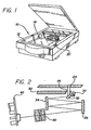
- the present invention is concerned with scanners of the type shown in Figure 1 which have a carriage 20 mounted in a scanner 10 below a glass window 12 which receives the document to be scanned.
- the scanner carriage 20 is mounted on one or more spaced rods 14 or guide tracks for movement in the direction shown.
- a lamp 22 and reflector 24 are mounted in the carriage 20 proximate a slot 26 in the carriage cover 30 which receives reflected light and scanned information which is reflected from an angled narrow mirror 32 to an upper wide mirror 34, then to a lower wide mirror 36 in repeated fashion and finally passes through a lens assembly 40 mounted on the carriage to a CCD circuit 42 which electrically processes the scanned information.
- the scanner carriage 20 generally comprises a molded plastic chassis 50 and cover 30 which is affixed to the chassis 50 by screws 51 to form a housing in which the mirrors are positioned. Angled narrow mirror 32 is directly attached to the housing chassis 50 and held in place by spring clips 35.
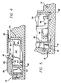
- the upper and lower mirrors 34, 36 are not directly connected to the chassis 50 but are maintained in precise spaced parallel relationship to each other by a pair of spaced flat sheet metal spacer plates 60, 62 oppositely facing the image plane sides of the respective mirrors.
- the upper mirror 34 engages spaced vertically extending rails 64, 66 which are molded on an interior wall of the chassis 50 on opposite sides of the lens assembly 40. Grooves in which the spacer plates are free to float or move in directions normal to the image planes of the upper and lower mirrors are also molded into the housing.
- the spacer plate grooves are defined by inside side walls of the chassis 50 and by abutments 68 molded on the floor of the housing.
- One of the two parallel mirrors 34, 36 is mounted at a slightly higher elevation in the chassis 50 so that the folded optical path shown in Figure 2 can be maintained.
- a pair of spaced identical sheet metal leaf springs 70 are received in slots 72 formed in the chassis 50 and urge the lower mirror 36 to the right as seen in Figure 4 into engagement with the spacer plates 60, 62 which are likewise urged to the right into firm engagement with the upper mirror 34 which in turn is urged against the rails 64, 66 to maintain the precise position, spacing and parallelism of the mirrors in the chassis as required.
- the underside of the housing cover 30 is preferably molded with spaced apertures 38 which receive four elastomeric compressible pads 80, 81, 82, 83 positioned as shown in Figures 3 and 4 which, when the cover is screwed onto the chassis 50 to form the housing, are partially compressed and engage an upper edge of the upper mirror 34 and the spacer plates 60, 62 to firmly affix them in the required position without the need of affixation screws or spring clips or the equivalent.
- First and second elastomeric pads 81, 83 engage both an upper side edge of the upper mirror 34 as well as an upper edge of the respective spacer plates 60, 62 at locations proximate their points of contact with the upper mirror.
- Third and fourth elastomeric pads 80, 82 engage the upper edges of the spacer plates 60, 62 proximate the points of contact of the spacer plates with the lower mirror 36 but do not engage the lower mirror 36 itself.
- the spacer plates 60, 62 are identical with each other and are formed from flat pieces of sheet metal and have upper and lower projecting fingers 64, 65, 66, 67 at the opposite mirror-engaging edges which contact the upper and lower mirrors on the facing image plane sides thereof.
- the spacer plates 60, 62 can be substantially identical sheet metal parts as can the biasing springs 70, 72, economies of manufacture and assembly result. It will also be noted that the spacer plates are freely movable with respect to the chassis 50 in spaced paths which intersect the image planes of the mirrors and that the springs 70 do not contact the image plane sides of the mirrors whereby the image plane sides are substantially unobstructed except for the points of contact with the spacer plates. This enables the scanner carriage to occupy a relatively small footprint and enable use of a larger portion of the mirrors than otherwise possible.
- the spacer plates 60, 62 are free to move in and occupy spaced planes which are normal to the image planes of the mirrors 34, 36; however, other arrangements in which the planes of the spacer plates are not necessarily normal to the image planes of the mirrors and arrangements in which the spacer plates are not parallel to each other are contemplated.
Landscapes
- Engineering & Computer Science (AREA)
- Multimedia (AREA)
- Signal Processing (AREA)
- Facsimile Scanning Arrangements (AREA)
- Optical Systems Of Projection Type Copiers (AREA)
Claims (8)
- Ein Scannerwagen, der ein Gehäuse aufweist, das eine Mehrzahl von Spiegeln enthält, die einen gefalteten optischen Lichtweg zum Übertragen eines gescannten Bildes an eine Linsenanordnung liefern, wobei der Wagen durch folgendes gekennzeichnet ist: beabstandete erste und zweite Spiegel (34, 36), die Bildebenen, die parallel bleiben müssen, aufweisen, wobei sich ein erster (34) der Spiegel in Kontakt mit einer durch das Gehäuse definierten Referenzebene befindet, ein Paar von starren Abstandshalterplatten (60, 62), die Enden aufweisen, die zugewandte Bildebenenseiten der Spiegel berühren, wobei die Abstandshalterplatten bezüglich des Gehäuses in beabstandeten Pfaden, die die Bildebenen der Spiegel schneiden, frei beweglich sind, und eine nachgiebige Einrichtung (70), die einen zweiten (36) der Spiegel in Eingriff nimmt, ohne die Bildebenenseite desselben zu berühren, um den zweiten der Spiegel zu den Abstandshalterplatten und zu dem ersten der Spiegel hinzudrücken.
- Der Scannerwagen gemäß Anspruch 1, dadurch gekennzeichnet, daß die beabstandeten Pfade, in denen die Abstandshalterplatten (60, 62) frei beweglich sind, parallel sind.
- Der Scannerwagen gemäß Anspruch 1 oder 2, dadurch gekennzeichnet, daß die Spiegel (34, 36) rechteckig sind und die Abstandshalterplatten (60, 62) die Spiegel in der Nähe der Enden der Spiegel berühren.
- Der Scannerwagen gemäß Anspruch 1, 2 oder 3, ferner gekennzeichnet durch Führungskanäle an dem Gehäuse zum Aufnehmen der Abstandshalterplatten (60, 62), wobei sich die Führungskanäle parallel zu den Abstandshalterplatten erstrecken und eine Bewegung der Abstandshalterplatten in den Kanälen erlauben.
- Der Scannerwagen gemäß einem der vorhergehenden Ansprüche, dadurch gekennzeichnet, daß die nachgiebige Einrichtung zumindest eine an dem Gehäuse befestigte gebogene Blattfeder (70) aufweist, wobei die Blattfeder eine Rückseite des zweiten Spiegels (36) gegenüber der Bildebene in Eingriff nimmt.
- Der Scannerwagen gemäß einem der vorhergehenden Ansprüche, dadurch gekennzeichnet, daß das Gehäuse eine Abdeckung (30) aufweist, wobei jeder des ersten und des zweiten Spiegels (34, 36) eine Seitenkante aufweist und in dem Gehäuse getragen ist, wobei die Enden der starren Abstandhalterplatten (60, 62) in der Nähe beabstandeter Enden der Spiegel sind, und eine komprimierte nachgiebige Einrichtung (80-83) aufweist, die eine erste Seite, die mit der Abdeckung (30) in Eingriff steht, und eine zweite Seite hat, die mit einer Seitenkante des ersten Spiegels (34) und mit einer entsprechenden Abstandshalterplatte (60, 62), die in der Nähe der Bildebenenseite des ersten Spiegels ist, in Eingriff steht.
- Der Scannerwagen gemäß Anspruch 6, dadurch gekennzeichnet, daß die nachgiebige Einrichtung eine erste und eine zweite beabstandete elastomere Einlage (80, 82) aufweist, wobei jede Einlage zwischen der Abdekkung (30) und einer entsprechenden Abstandshalterplatte (60, 62) und einer Seitenkante des ersten Spiegels (34) komprimiert wird.
- Der Scannerwagen gemäß Anspruch 7, ferner gekennzeichnet durch eine dritte und eine vierte elastomere Einlage (81, 83), wobei sowohl die dritte als auch die vierte Einlage zwischen der Abdeckung (30) und einer entsprechenden Abstandshalterplatte (60, 62), die in der Nähe des Kontakts der Abstandshalterplatten mit der Bildebenenseite des zweiten Spiegels (36) ist, komprimiert werden.
Applications Claiming Priority (2)
| Application Number | Priority Date | Filing Date | Title |
|---|---|---|---|
| US6312 | 1998-01-13 | ||
| US09/006,312 US5973796A (en) | 1998-01-13 | 1998-01-13 | Scanner carriage mirror mounting to reduce footprint |
Publications (3)
| Publication Number | Publication Date |
|---|---|
| EP0929178A2 EP0929178A2 (de) | 1999-07-14 |
| EP0929178A3 EP0929178A3 (de) | 2000-07-26 |
| EP0929178B1 true EP0929178B1 (de) | 2003-12-03 |
Family
ID=21720284
Family Applications (1)
| Application Number | Title | Priority Date | Filing Date |
|---|---|---|---|
| EP99300117A Expired - Lifetime EP0929178B1 (de) | 1998-01-13 | 1999-01-07 | Ausrichtungsfehler reduzierende Spiegelhalterung in einem Abtastwagen |
Country Status (4)
| Country | Link |
|---|---|
| US (1) | US5973796A (de) |
| EP (1) | EP0929178B1 (de) |
| DE (1) | DE69913212T2 (de) |
| TW (1) | TW385606B (de) |
Families Citing this family (6)
| Publication number | Priority date | Publication date | Assignee | Title |
|---|---|---|---|---|
| US6115109A (en) * | 1998-06-04 | 2000-09-05 | Fujifilm Electronics Imaging Ltd. | Apparatus and method for scanning a light beam over an image surface |
| US6252684B1 (en) * | 1998-11-13 | 2001-06-26 | Umax Data Systems Inc. | Automatic paper feeder including an upper light source |
| US6562906B2 (en) * | 2000-08-11 | 2003-05-13 | E. I. Du Pont De Nemours And Company | Bi-modal ionomers |
| JP2003295342A (ja) * | 2002-03-29 | 2003-10-15 | Fuji Photo Optical Co Ltd | 画像読取装置の反射鏡取付構造 |
| JP4174282B2 (ja) * | 2002-10-01 | 2008-10-29 | キヤノン株式会社 | 画像読取装置 |
| JP2009111544A (ja) * | 2007-10-29 | 2009-05-21 | Toshiba Corp | 密着型イメージセンサ、及び画像形成装置 |
Family Cites Families (12)
| Publication number | Priority date | Publication date | Assignee | Title |
|---|---|---|---|---|
| JPS604368A (ja) * | 1983-06-21 | 1985-01-10 | Sharp Corp | 光学読取装置 |
| US4847641A (en) * | 1988-08-16 | 1989-07-11 | Hewlett-Packard Company | Piece-wise print image enhancement for dot matrix printers |
| US5005139A (en) * | 1988-08-16 | 1991-04-02 | Hewlett-Packard Company | Piece-wise print image enhancement for dot matrix printers |
| JP2806401B2 (ja) * | 1991-02-12 | 1998-09-30 | 富士ゼロックス株式会社 | ラスタ走査装置の反射ミラー支持構造 |
| US5341225A (en) * | 1991-05-14 | 1994-08-23 | Hewlett-Packard Company | Image scanning system and method with improved repositioning |
| US5239313A (en) * | 1992-07-24 | 1993-08-24 | Hewlett-Packard Company | Continuously variable resolution laser printer |
| US5410347A (en) * | 1992-08-19 | 1995-04-25 | Hewlett-Packard Company | Color optical scanner with image registration holding assembly |
| US5452110A (en) * | 1993-04-21 | 1995-09-19 | Matsushita Graphic Communication Systems, Inc. | Compact facsimile apparatus with improved component arrangement |
| US5336878A (en) * | 1993-05-10 | 1994-08-09 | Hewlett-Packard Company | Variable speed single pass color optical scanner |
| JP3707810B2 (ja) * | 1993-08-26 | 2005-10-19 | ヒューレット・パッカード・カンパニー | スキャナ用アダプタ |
| US5586212A (en) * | 1994-07-06 | 1996-12-17 | Hewlett-Packard | Optical wave guide for hand-held scanner |
| JP3746806B2 (ja) * | 1995-02-28 | 2006-02-15 | ペンタックス株式会社 | 画像読取り装置 |
-
1998
- 1998-01-13 US US09/006,312 patent/US5973796A/en not_active Expired - Lifetime
- 1998-06-29 TW TW087110465A patent/TW385606B/zh not_active IP Right Cessation
-
1999
- 1999-01-07 EP EP99300117A patent/EP0929178B1/de not_active Expired - Lifetime
- 1999-01-07 DE DE1999613212 patent/DE69913212T2/de not_active Expired - Lifetime
Also Published As
| Publication number | Publication date |
|---|---|
| DE69913212T2 (de) | 2004-11-18 |
| TW385606B (en) | 2000-03-21 |
| EP0929178A2 (de) | 1999-07-14 |
| EP0929178A3 (de) | 2000-07-26 |
| DE69913212D1 (de) | 2004-01-15 |
| US5973796A (en) | 1999-10-26 |
Similar Documents
| Publication | Publication Date | Title |
|---|---|---|
| US5211464A (en) | Illuminating device, particularly for displays of data processing devices | |
| EP0648376B1 (de) | Anordnung einer bildwandlereinheit. | |
| JP3228460B2 (ja) | フローティング電気コネクタ | |
| JP2010283436A (ja) | 読取装置 | |
| JP2924927B2 (ja) | イメージセンサ | |
| EP0929178B1 (de) | Ausrichtungsfehler reduzierende Spiegelhalterung in einem Abtastwagen | |
| US5381243A (en) | Arrangement and method for attaching image sensor to electronic machine | |
| KR100800213B1 (ko) | 상대측 커넥터와 감합에 의해 감합부의 플로팅이 조절되는커넥터 | |
| JP4221787B2 (ja) | コンデンサレンズの係着構造 | |
| US5157536A (en) | Optical apparatus having spring holding means for lenses | |
| US5973815A (en) | Scanner carriage lamp reflector and method of using same | |
| JPH058573Y2 (de) | ||
| US4647768A (en) | Image sensing head for document scanning | |
| JPH0588064A (ja) | 光学素子の支持装置 | |
| JP3781252B2 (ja) | 画像読取装置 | |
| JP3364542B2 (ja) | 画像読取装置 | |
| CN111886851B (zh) | 图像传感器用安装金属配件及使用其的图像传感器装置 | |
| JP3443258B2 (ja) | 画像読取装置 | |
| US5866892A (en) | Apparatus for optical reading of information optical reader of information having an integrally formed housing for optical equipment | |
| JP2010124189A (ja) | 読取装置 | |
| JP2002237915A (ja) | 電波ノイズの放射防止構造体及びそれを用いた画像読取装置 | |
| JP2000148040A (ja) | 表示パネル装置の部品固定構造 | |
| JP2575228Y2 (ja) | カードの保持装置 | |
| JPH0641253Y2 (ja) | フイルタ保持装置 | |
| KR0181801B1 (ko) | 팩시밀리의 밀착이미지센서 체결장치 |
Legal Events
| Date | Code | Title | Description |
|---|---|---|---|
| PUAI | Public reference made under article 153(3) epc to a published international application that has entered the european phase |
Free format text: ORIGINAL CODE: 0009012 |
|
| AK | Designated contracting states |
Kind code of ref document: A2 Designated state(s): DE FR GB |
|
| AX | Request for extension of the european patent |
Free format text: AL;LT;LV;MK;RO;SI |
|
| PUAL | Search report despatched |
Free format text: ORIGINAL CODE: 0009013 |
|
| AK | Designated contracting states |
Kind code of ref document: A3 Designated state(s): AT BE CH CY DE DK ES FI FR GB GR IE IT LI LU MC NL PT SE |
|
| AX | Request for extension of the european patent |
Free format text: AL;LT;LV;MK;RO;SI |
|
| 17P | Request for examination filed |
Effective date: 20010105 |
|
| AKX | Designation fees paid |
Free format text: DE FR GB |
|
| RAP1 | Party data changed (applicant data changed or rights of an application transferred) |
Owner name: HEWLETT-PACKARD COMPANY, A DELAWARE CORPORATION |
|
| 17Q | First examination report despatched |
Effective date: 20030129 |
|
| GRAH | Despatch of communication of intention to grant a patent |
Free format text: ORIGINAL CODE: EPIDOS IGRA |
|
| GRAS | Grant fee paid |
Free format text: ORIGINAL CODE: EPIDOSNIGR3 |
|
| GRAA | (expected) grant |
Free format text: ORIGINAL CODE: 0009210 |
|
| AK | Designated contracting states |
Kind code of ref document: B1 Designated state(s): DE FR GB |
|
| REG | Reference to a national code |
Ref country code: GB Ref legal event code: FG4D |
|
| REF | Corresponds to: |
Ref document number: 69913212 Country of ref document: DE Date of ref document: 20040115 Kind code of ref document: P |
|
| ET | Fr: translation filed | ||
| PLBE | No opposition filed within time limit |
Free format text: ORIGINAL CODE: 0009261 |
|
| STAA | Information on the status of an ep patent application or granted ep patent |
Free format text: STATUS: NO OPPOSITION FILED WITHIN TIME LIMIT |
|
| 26N | No opposition filed |
Effective date: 20040906 |
|
| PGFP | Annual fee paid to national office [announced via postgrant information from national office to epo] |
Ref country code: FR Payment date: 20070207 Year of fee payment: 9 |
|
| REG | Reference to a national code |
Ref country code: FR Ref legal event code: ST Effective date: 20081029 |
|
| PG25 | Lapsed in a contracting state [announced via postgrant information from national office to epo] |
Ref country code: FR Free format text: LAPSE BECAUSE OF NON-PAYMENT OF DUE FEES Effective date: 20080131 |
|
| PGFP | Annual fee paid to national office [announced via postgrant information from national office to epo] |
Ref country code: GB Payment date: 20100125 Year of fee payment: 12 Ref country code: DE Payment date: 20100127 Year of fee payment: 12 |
|
| GBPC | Gb: european patent ceased through non-payment of renewal fee |
Effective date: 20110107 |
|
| PG25 | Lapsed in a contracting state [announced via postgrant information from national office to epo] |
Ref country code: GB Free format text: LAPSE BECAUSE OF NON-PAYMENT OF DUE FEES Effective date: 20110107 |
|
| REG | Reference to a national code |
Ref country code: DE Ref legal event code: R119 Ref document number: 69913212 Country of ref document: DE Effective date: 20110802 |
|
| PG25 | Lapsed in a contracting state [announced via postgrant information from national office to epo] |
Ref country code: DE Free format text: LAPSE BECAUSE OF NON-PAYMENT OF DUE FEES Effective date: 20110802 |