EP0929372B1 - Fräser - Google Patents
Fräser Download PDFInfo
- Publication number
- EP0929372B1 EP0929372B1 EP97943273A EP97943273A EP0929372B1 EP 0929372 B1 EP0929372 B1 EP 0929372B1 EP 97943273 A EP97943273 A EP 97943273A EP 97943273 A EP97943273 A EP 97943273A EP 0929372 B1 EP0929372 B1 EP 0929372B1
- Authority
- EP
- European Patent Office
- Prior art keywords
- end mill
- head
- tool
- mill head
- center axis
- Prior art date
- Legal status (The legal status is an assumption and is not a legal conclusion. Google has not performed a legal analysis and makes no representation as to the accuracy of the status listed.)
- Expired - Lifetime
Links
Images




Classifications
-
- B—PERFORMING OPERATIONS; TRANSPORTING
- B23—MACHINE TOOLS; METAL-WORKING NOT OTHERWISE PROVIDED FOR
- B23B—TURNING; BORING
- B23B31/00—Chucks; Expansion mandrels; Adaptations thereof for remote control
- B23B31/02—Chucks
- B23B31/10—Chucks characterised by the retaining or gripping devices or their immediate operating means
- B23B31/11—Retention by threaded connection
-
- B—PERFORMING OPERATIONS; TRANSPORTING
- B23—MACHINE TOOLS; METAL-WORKING NOT OTHERWISE PROVIDED FOR
- B23B—TURNING; BORING
- B23B29/00—Holders for non-rotary cutting tools; Boring bars or boring heads; Accessories for tool holders
- B23B29/03—Boring heads
-
- B—PERFORMING OPERATIONS; TRANSPORTING
- B23—MACHINE TOOLS; METAL-WORKING NOT OTHERWISE PROVIDED FOR
- B23C—MILLING
- B23C5/00—Milling-cutters
- B23C5/02—Milling-cutters characterised by the shape of the cutter
- B23C5/10—Shank-type cutters, i.e. with an integral shaft
-
- B—PERFORMING OPERATIONS; TRANSPORTING
- B23—MACHINE TOOLS; METAL-WORKING NOT OTHERWISE PROVIDED FOR
- B23C—MILLING
- B23C5/00—Milling-cutters
- B23C5/28—Features relating to lubricating or cooling
- B23C5/283—Cutting inserts with internal coolant channels
-
- B—PERFORMING OPERATIONS; TRANSPORTING
- B23—MACHINE TOOLS; METAL-WORKING NOT OTHERWISE PROVIDED FOR
- B23Q—DETAILS, COMPONENTS, OR ACCESSORIES FOR MACHINE TOOLS, e.g. ARRANGEMENTS FOR COPYING OR CONTROLLING; MACHINE TOOLS IN GENERAL CHARACTERISED BY THE CONSTRUCTION OF PARTICULAR DETAILS OR COMPONENTS; COMBINATIONS OR ASSOCIATIONS OF METAL-WORKING MACHINES, NOT DIRECTED TO A PARTICULAR RESULT
- B23Q11/00—Accessories fitted to machine tools for keeping tools or parts of the machine in good working condition or for cooling work; Safety devices specially combined with or arranged in, or specially adapted for use in connection with, machine tools
- B23Q11/0042—Devices for removing chips
-
- B—PERFORMING OPERATIONS; TRANSPORTING
- B23—MACHINE TOOLS; METAL-WORKING NOT OTHERWISE PROVIDED FOR
- B23Q—DETAILS, COMPONENTS, OR ACCESSORIES FOR MACHINE TOOLS, e.g. ARRANGEMENTS FOR COPYING OR CONTROLLING; MACHINE TOOLS IN GENERAL CHARACTERISED BY THE CONSTRUCTION OF PARTICULAR DETAILS OR COMPONENTS; COMBINATIONS OR ASSOCIATIONS OF METAL-WORKING MACHINES, NOT DIRECTED TO A PARTICULAR RESULT
- B23Q11/00—Accessories fitted to machine tools for keeping tools or parts of the machine in good working condition or for cooling work; Safety devices specially combined with or arranged in, or specially adapted for use in connection with, machine tools
- B23Q11/10—Arrangements for cooling or lubricating tools or work
- B23Q11/1015—Arrangements for cooling or lubricating tools or work by supplying a cutting liquid through the spindle
- B23Q11/1023—Tool holders, or tools in general specially adapted for receiving the cutting liquid from the spindle
-
- B—PERFORMING OPERATIONS; TRANSPORTING
- B23—MACHINE TOOLS; METAL-WORKING NOT OTHERWISE PROVIDED FOR
- B23C—MILLING
- B23C2210/00—Details of milling cutters
- B23C2210/03—Cutting heads comprised of different material than the shank irrespective of whether the head is detachable from the shank
-
- Y—GENERAL TAGGING OF NEW TECHNOLOGICAL DEVELOPMENTS; GENERAL TAGGING OF CROSS-SECTIONAL TECHNOLOGIES SPANNING OVER SEVERAL SECTIONS OF THE IPC; TECHNICAL SUBJECTS COVERED BY FORMER USPC CROSS-REFERENCE ART COLLECTIONS [XRACs] AND DIGESTS
- Y10—TECHNICAL SUBJECTS COVERED BY FORMER USPC
- Y10T—TECHNICAL SUBJECTS COVERED BY FORMER US CLASSIFICATION
- Y10T279/00—Chucks or sockets
- Y10T279/16—Longitudinal screw clamp
-
- Y—GENERAL TAGGING OF NEW TECHNOLOGICAL DEVELOPMENTS; GENERAL TAGGING OF CROSS-SECTIONAL TECHNOLOGIES SPANNING OVER SEVERAL SECTIONS OF THE IPC; TECHNICAL SUBJECTS COVERED BY FORMER USPC CROSS-REFERENCE ART COLLECTIONS [XRACs] AND DIGESTS
- Y10—TECHNICAL SUBJECTS COVERED BY FORMER USPC
- Y10T—TECHNICAL SUBJECTS COVERED BY FORMER US CLASSIFICATION
- Y10T407/00—Cutters, for shaping
- Y10T407/19—Rotary cutting tool
- Y10T407/1906—Rotary cutting tool including holder [i.e., head] having seat for inserted tool
- Y10T407/1908—Face or end mill
- Y10T407/192—Face or end mill with separate means to fasten tool to holder
-
- Y—GENERAL TAGGING OF NEW TECHNOLOGICAL DEVELOPMENTS; GENERAL TAGGING OF CROSS-SECTIONAL TECHNOLOGIES SPANNING OVER SEVERAL SECTIONS OF THE IPC; TECHNICAL SUBJECTS COVERED BY FORMER USPC CROSS-REFERENCE ART COLLECTIONS [XRACs] AND DIGESTS
- Y10—TECHNICAL SUBJECTS COVERED BY FORMER USPC
- Y10T—TECHNICAL SUBJECTS COVERED BY FORMER US CLASSIFICATION
- Y10T407/00—Cutters, for shaping
- Y10T407/19—Rotary cutting tool
- Y10T407/1906—Rotary cutting tool including holder [i.e., head] having seat for inserted tool
- Y10T407/1908—Face or end mill
- Y10T407/1924—Specified tool shape
-
- Y—GENERAL TAGGING OF NEW TECHNOLOGICAL DEVELOPMENTS; GENERAL TAGGING OF CROSS-SECTIONAL TECHNOLOGIES SPANNING OVER SEVERAL SECTIONS OF THE IPC; TECHNICAL SUBJECTS COVERED BY FORMER USPC CROSS-REFERENCE ART COLLECTIONS [XRACs] AND DIGESTS
- Y10—TECHNICAL SUBJECTS COVERED BY FORMER USPC
- Y10T—TECHNICAL SUBJECTS COVERED BY FORMER US CLASSIFICATION
- Y10T407/00—Cutters, for shaping
- Y10T407/19—Rotary cutting tool
- Y10T407/1946—Face or end mill
- Y10T407/1948—Face or end mill with cutting edge entirely across end of tool [e.g., router bit, end mill, etc.]
-
- Y—GENERAL TAGGING OF NEW TECHNOLOGICAL DEVELOPMENTS; GENERAL TAGGING OF CROSS-SECTIONAL TECHNOLOGIES SPANNING OVER SEVERAL SECTIONS OF THE IPC; TECHNICAL SUBJECTS COVERED BY FORMER USPC CROSS-REFERENCE ART COLLECTIONS [XRACs] AND DIGESTS
- Y10—TECHNICAL SUBJECTS COVERED BY FORMER USPC
- Y10T—TECHNICAL SUBJECTS COVERED BY FORMER US CLASSIFICATION
- Y10T407/00—Cutters, for shaping
- Y10T407/23—Cutters, for shaping including tool having plural alternatively usable cutting edges
-
- Y—GENERAL TAGGING OF NEW TECHNOLOGICAL DEVELOPMENTS; GENERAL TAGGING OF CROSS-SECTIONAL TECHNOLOGIES SPANNING OVER SEVERAL SECTIONS OF THE IPC; TECHNICAL SUBJECTS COVERED BY FORMER USPC CROSS-REFERENCE ART COLLECTIONS [XRACs] AND DIGESTS
- Y10—TECHNICAL SUBJECTS COVERED BY FORMER USPC
- Y10T—TECHNICAL SUBJECTS COVERED BY FORMER US CLASSIFICATION
- Y10T407/00—Cutters, for shaping
- Y10T407/27—Cutters, for shaping comprising tool of specific chemical composition
-
- Y—GENERAL TAGGING OF NEW TECHNOLOGICAL DEVELOPMENTS; GENERAL TAGGING OF CROSS-SECTIONAL TECHNOLOGIES SPANNING OVER SEVERAL SECTIONS OF THE IPC; TECHNICAL SUBJECTS COVERED BY FORMER USPC CROSS-REFERENCE ART COLLECTIONS [XRACs] AND DIGESTS
- Y10—TECHNICAL SUBJECTS COVERED BY FORMER USPC
- Y10T—TECHNICAL SUBJECTS COVERED BY FORMER US CLASSIFICATION
- Y10T408/00—Cutting by use of rotating axially moving tool
- Y10T408/89—Tool or Tool with support
- Y10T408/907—Tool or Tool with support including detailed shank
Definitions
- the present invention relates to a tool and a tool head according to the preambles of claims 1 and 5.
- a previously known end mill with a detachable head is disclosed in JP patent document No. 57-189713.
- the known tool includes a neck portion that is integral with the end mill head, which neck portion constitutes a potential breakage area for the tool.
- Another problem with such prior art is that it has been found unstable in some high speed applications, due to the lack of support at radially outward surfaces.
- unnecessarily expensive tool material is used in the neck portion.
- US-A-4,964,762 on which the preambles of the independent claims 1 and 5 are based, discloses a face milling cutter having indexable cutting inserts.
- An object of the present invention is to provide an end mill in which performance and useful life are improved.
- Another object of the present invention is to provide an end mill that has an extremely good stability such that a machined surface can be obtained which is substantially free from chatter marks.
- Still another object of the present invention is to provide an easily mountable end mill.
- Still another object of the present invention is to provide an end mill, which due to its configuration saves expensive cutting tool material.
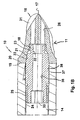
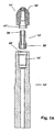
- Figs. 1A and 1B show an embodiment of a detachable ball nose end mill 10 according to the present invention.
- the end mill 10 comprises a mill head 11, a pull rod or screw 12 and a shank 13.
- the pull rod 12 is threaded into the mill head 11 and the pull rod is further connected to the shank 13.
- the shank is preferably held in a rotatable spindle in a milling or drilling machine, not shown.
- the shank 13 has a hole 14 into which the pull rod 12 is fitted.
- the end mill head 11 has cutting edge means 15, such as two identical cutting edges 16 extending at least from the outermost point of the head towards the center axis 17 of the tool.
- the cutting edge means 15 may alternatively include three or four identical cutting edges.
- the cutting edges 16 preferably meet in the vicinity of the center axis 17.
- the end mill head and the shank comprise cooperating abutment surfaces 19 and 20.
- the abutment surfaces are preferably planar and extend generally perpendicularly to the center axis 17 of the end mill.
- the cutting edge means 15 follow a path, which is larger than 180° so as to allow outcopying during upwardly directed feed.
- the path is preferably circular and its largest diameter is larger than the diameter of the abutment surface 19 and the diameter of the shank.
- the largest diameter of the abutment surface 19 of the mill head and the outer diameter of the abutment surface 20 of the shank are substantially identical.
- Each cutting edge 16 lies in a plane P which forms an acute angle ⁇ with the center axis 17, when seen in a view as shown in Fig. 3B.
- the angle ⁇ is 5 to 15°, preferably about 10°.
- the pull rod 12 is separable from the end mill head by means of threads 18 or bayonet means, the latter not shown.
- the end mill head does not extend axially rearwards of the plane of the surfaces 19 and 20.
- the pull rod and the end mill head comprise conical cooperating centering surfaces 21 and 22.
- the centering surfaces 21 and 22 taper at an acute angle ⁇ relative to the center axis 17 towards an axially forward free end 34 of the pull rod, Fig. 1B.
- the angle ⁇ is between 1 to 20°, preferably 5 to 10°.
- the end mill head is made from material harder than the material of the pull rod.
- the end mill head is manufactured by mixing powder of sintered hard alloy or cermet with an organic binder such as plastics and forming the mixture to pellets or granulates, moulding the pellets or granulates according to an injection moulding process and sintering the obtained product at a temperature of 1300 to 1500°C.
- the pull rod is preferably made from steel, which is relatively inexpensive.
- the free ends of the pull rod comprise fastening means, such as threads 23 and 25 and/or bayonet means, for engagement with corresponding fastening means 18 and 24, respectively, in the end mill head and in the shank.
- the end mill head has holes 26 for promoting pressurized medium, such as air or liquid, to remove chips and the medium is supplied from the tool holder, not shown.
- the end mill head comprises external key grip means 27 for mounting and dismounting.
- the end mill head 11 for cutting material during its revolution about the center axis 17 further comprises clearance means 28, a first recess 29, having centering means 22 therein, and a second recess 30, having fastening means 18 therein.
- At least two substantially parallel flushing channels 26 are provided in the end mill head, extending from the second recess 30 and terminating in chip flutes or rake faces 31 of the end mill head.
- the recesses 29, 30 make a penetrated blind hole, i.e. a hole with a certain depth at which the flushing channels 26 connect. Said hole has a substantially decreasing cross-sectional area in direction towards the cutting edge means 15.
- the elongated pull rod to be used in the rotatable ballnose end mill further comprises key grip means 32 and 33, such as hexagon wrench holes for Allen keys, at the first free end 34 and a second free end 35, respectively.
- the centering surface 21 is provided closer to the first free end 34 than to the second free end 35 of the pull rod.
- the diameter of the first free end 34 is smaller than the diameter of the second free end 35.
- a longitudinally extending hole 36 is provided in the pull rod, said hole extending from one free end to another for the promotion of pressurized medium, such as liquid or air. Medium to remove chips is supplied through the hole 36 and the flush channels.
- the pull rod 12 is mounted by inserting the rod into the hole 14 of the shank 13 and by rotating the rod with a key, not shown, in the grip 32 or 33 to a predetermined depth.
- the threads 25 of the rod will then engage the threads 24 of the shank.
- the portions 37 and 38 are manufactured with small tolerances so as to provide a slip fit and to minimize relative radial movement.
- at least one of the threads 24 and 25 is provided with a locking medium, such as plastics, so as to increase the resistance against unscrewing.
- the end mill head 11 is then placed over the free end 34 of the rod and is rotated such that the engagement of threads 18 and 23 draw the head axially towards the shank until the centering surfaces 21 and 22 engage and center the mill head. Further rotation of the head, by means of a wrench acting externally on the key grip means 27, will result in rotation also of the rod 12 until the abutment surfaces 19 and 20 will come into contact and stop further axial movement of rod and head.
- Figs. 7A through 13 an alternative embodiment of a tool according to the present invention will be described. It is understood that like numerals depict like details as described in connection with the previous embodiment.
- Figs 9A and 9B show an embodiment of a detachable ball nose end mill 10 comprising a mill head 11', a pull rod or screw 12' and a shank 13'.
- the pull rod 12' is screwn into the mill head 11' and the pull rod is further connected to the shank 13'.
- the shank 13' has a hole 14' into which the pull rod 12' is fitted.
- the end mill head 11' has cutting edge means 15' such as two identical cutting edges 16' extending at least from the outermost point of the head towards the center axis 17' of the tool.
- the cutting edge means 15' may alternatively include three or four identical cutting edges.
- the cutting edges 16' preferably meet in the vicinity of the center axis 17'.
- the end mill head and the shank comprise cooperating abutment surfaces 19' and 20'.
- the abutment surfaces are preferably planar and extend generally perpendicularly to the center axis 17' of the end mill.
- the cutting edge means 15' follow a path, which is larger than 180° so as to allow outcopying during upwardly directed feed.
- the path is preferably circular and its largest diameter is larger than the diameter of the abutment surface 19' and the diameter of the shank.
- the largest diameter of the abutment surface 19' of the mill head and the outer diameter of the abutment surface 20' of the shank are substantially equal.
- Each cutting edge 16' lies in a plane P' which forms an acute angle ⁇ ' with the center axis 17', when seen in a view as shown in Fig. 9B.
- the angle ⁇ ' is 5 to 15°, preferably about 10°.
- the pull rod 12' is separable from the end mill head by means of threads 18' or bayonet means, the latter not shown.
- the end mill head extend partially axially rearwards of the plane of the surfaces 19' and 20'.
- the shank and the end mill head comprise substantially cylindrical cooperating centering surfaces 21' and 22', respectively.
- the centering surface 21' of the shank is located in a recess 40' in the forward free end of the shank.
- the centering surface 22' of the mill head is located externally on a projection 41' extending rearwardly of the abutment surface 19', a distance L.
- the centering surfaces 21' and 22' extend substantially parallel to the center axis 17'.
- the end mill head is made from material harder than the material of the pull rod. The threads 25' of the rod will then engage the threads 24' of the shank.
- the end mill head is manufactured by mixing powder of sintered hard alloy or cermet with an organic binder such as plastics and forming the mixture to pellets or granulates, molding the pellets or granulates according to an injection molding process and sintering the obtained product at a temperature of 1300 to 1500°C.
- the pull rod is preferably made from steel, which is relatively inexpensive.
- the free ends of the pull rod comprise fastening means, such as threads 23' and 25' and/or bayonet means, for engagement with corresponding fastening means 18' and 24', respectively, in the end mill head and in the shank.
- the end mill head has holes 26' for promoting pressurized medium, such as air or liquid, to remove chips and the medium is supplied from the tool holder, not shown.
- the end mill head comprises external key grip means 27' for mounting and dismounting.
- the end mill head 11' for cutting material during its revolution about the center axis 17' further comprises clearance means 28', a first recess 29', having centering means 22' therein, and a second recess 30, having fastening means 18' therein.
- At least two flushing channels 26' are provided in the end mill head, extending from the second recess 30' and terminating in chip flutes or rake faces 31' of the end mill head.
- the elongated pull rod to be used in the rotatable ballnose end mill further comprises key grip means, such as hexagon wrench holes for Allen keys, at the first free end 34' and a second free end 35', respectively.
- the diameter of the first free end 34' is smaller than the diameter of the second free end 35'.
- a longitudinally extending hole 36' is provided in the pull rod, said hole extending from one free end to another for the promotion of pressurized medium, such as liquid or air. Medium to remove chips is supplied through the hole 36' and the flush holes 26'.
- the pull rod 12' is mounted by inserting it into the hole 14' of the shank 13' and by rotating the rod with a key, not shown, from the front or from the rear into the grip means 32' or 33', respectively, to a predetermined depth.
- the threads 25' of the rod will then engage the threads 24' of the shank.
- the end mill head 11' is then placed over the free end 34' of the rod and is rotated such that the engagement of threads 18' and 23' draw the head axially towards the shank until the centering surfaces 21' and 22' engage and center the mill head.
- the surfaces 21' and 22' are manufactured with small tolerances so as to provide a slip fit and to minimize relative radial movement.
- at least one of the threads 24' and 25' is provided with a locking medium, such as plastics, so as to increase the resistance against unscrewing.
- the end mill heads are preferably made in injection moulded tungsten carbide and have integrated threads placed axially forwards of the planar abutment surfaces.
- the mill head describes the largest diameter of the entire tool.
- the pull rods are externally threaded at all free ends and they include a central channel for distribution of a flush medium to be transferred to a widened space and successively through the flush channels to the cutting edge area.
- the pull rod is positioned in the vicinity of the forward end of each shank. There are key grips for rotation of each end mill head during assembling.
- each embodiment of the tool according to the present invention differ in that in the first case the centering surfaces are positioned internally in the mill head and externally on the pull rod while tapering forwardly. In the other case, the centering surfaces are positioned externally on the mill head and internally on the shank while being parallel with the rotational axis of the tool.
Landscapes
- Engineering & Computer Science (AREA)
- Mechanical Engineering (AREA)
- Milling Processes (AREA)
Claims (8)
- Werkzeug (10; 10') mit einem Werkzeugkopf (11; 11'), einer Zugstange (12; 12') und einem Schaft (13; 13') mit einem Loch (14; 14'), in welches die Zugstange eingepaßt ist, wobei der Werkzeugkopf eine Schneidkanteneinrichtung (15; 15') und eine Befestigungseinrichtung (18; 18') hat, der Werkzeugkopf (11; 11') eine radiale Zentriereinrichtung (22; 22') umfaßt, das Werkzeug eine Mittelachse (17; 17') hat, die Zugstange (12; 12') von dem Werkzeugkopf (11; 11') trennbar ist, der Werkzeugkopf und der Schaft (13; 13') zusammenwirkende Widerlagerflächen (19, 20; 19', 20') umfassen, wobei die Widerlagerflächen sich allgemein senkrecht zu der Mittelachse (17; 17') des Werkzeugs erstrecken, wobei sich die radiale Zentriereinrichtung (22; 22') im wesentlichen radial innerhalb der Widerlagerfläche (19; 19') befindet, dadurch gekennzeichnet, daß das Werkzeug ein Schaftfräser (10; 10') mit einem Schaftfräskopf (11; 11') aus Wolframcarbid ist und daß die Befestigungseinrichtung (18; 18') und die Schneidkanteneinrichtung (15; 15') integrale Bestandteile des Schaftfräskopfes sind.
- Werkzeug nach Anspruch 1, dadurch gekennzeichnet, daß der gesamte Schaftfräskopf aus einem Material besteht, das härter ist als das Material der Zugstange und daß freie Enden der Zugstange Befestigungseinrichtungen, wie etwa Gewinde und/oder Bajonetteinrichtungen, umfassen, um in entsprechende Befestigungseinrichtungen in dem Schaftfräskopf und in dem Schaft einzugreifen, und daß der Schaftfräskopf (11) und die Zugstange (12) zusammenarbeitende Zentrierflächen (21, 22) umfassen, wobei sich diese Zentrierflächen nach vorne hin in einem spitzen Winkel (α) in Bezug auf die Mittelachse (17) verjüngen oder daß der Schaftfräskopf (11') und der Schaft (13') zusammenarbeitende Zentrierflächen (21', 22') umfassen, wobei die Zentrierflächen im wesentlichen parallel zu der Mittelachse (17') sind.
- Werkzeug nach den Ansprüchen 1 oder 2, dadurch gekennzeichnet, daß der Schaftfräser Spülkanäle einschließt für die Unterstützung eines unter Druck befindlichen Mediums, wie etwa Luft oder eine Flüssigkeit, beim Entfernen von Spänen, und daß das Medium von einem ersten Kanal (14; 14') in dem Schaft (13; 13') durch einen zweiten Kanal (36; 36') in der Zugstange (12; 12') und weiter durch dritte Kanäle (26; 26') in dem Schaftfräskopf (11; 11') über einen mittleren geweiteten Raum (30; 30') in dem Schaftfräskopf zugeführt wird.
- Werkzeug nach den Ansprüchen 1, 2 oder 3, dadurch gekennzeichnet, daß die Schneidkanteneinrichtung (15; 15') einen Weg einschließt, welcher größer ist als 180° und daß das Material des Schaftfräskopfes (11; 11') eine spritzgegossene, gesinterte harte Legierung ist und daß der Schaftfräskopf eine äußere Schlüsselgriffeinrichtung (27; 27') für die Montage und Demontage umfaßt, und daß die Schneidkanteneinrichtung (15; 15'), wie etwa zwei identische Schneidkanten (16; 16'), sich wenigstens von dem äußersten Punkt des Kopfes zu der Mittelachse (17; 17') erstreckt, und daß die Schneidkanten sich bevorzugt in der Nähe der Mittelachse treffen.
- Werkzeugkopf für das Werkzeug gemäß Anspruch 1 für das Schneiden von Material während seiner Umdrehung um eine Mittelachse (17; 17') mit einer Schneideinrichtung (15, 15'), Abstandseinrichtung (28; 28') und Befestigungseinrichtung (18; 18'), wobei der Werkzeugkopf (11; 11') eine radiale Zentriereinrichtung (22; 22') umfaßt, der Werkzeugkopf eine Widerlagerfläche (19; 19') umfaßt, wobei die Widerlagerfläche sich allgemein senkrecht zu der Mittelachse (17; 17') erstreckt, wobei sich die radiale Zentriereinrichtung (22; 22') im wesentlichen radial innerhalb der Widerlagerfläche (19; 19') befindet, dadurch gekennzeichnet, daß das Werkzeug ein Schaftfräser (10; 10') mit einem Schaftfräskopf (11; 11') aus Wolframcarbid ist und daß die Befestigungseinrichtung (18; 18') und die Schneidkanteneinrichtung (15; 15') integrale Bestandteile des Schaftfräskopfes sind.
- Werkzeug nach Anspruch 5, dadurch gekennzeichnet, daß die Schneidkanteneinrichtung (15; 15'), wie etwa zwei identische Schneidkanten (16; 16'), sich wenigstens von dem äußersten Punkt des Kopfes zu der Mittelachse (17; 17') erstreckt, und daß die Schneidkanten sich bevorzugt in der Nähe der Mittelachse treffen und daß die Zentriereinrichtung (22; 22') sich nach vorne in einem spitzen Winkel (α) in Bezug auf die Mittelachse (17) verjüngt oder im wesentlichen parallel zu der Mittelachse (17') ist.
- Werkzeugkopf nach Anspruch 6, dadurch gekennzeichnet, daß die Schneideinrichtung (15; 15') einen Weg einschließt, welcher größer ist als 180° und daß das Material des Schaftfräskopfes eine spritzgegossene, gesinterte harte Legierung ist und daß der Schaftfräskopf eine äußere Schlüsselgriffeinrichtung (27; 27') umfaßt, und daß die Befestigungseinrichtung (18; 18') Gewinde oder Bajonetteinrichtungen umfaßt, die sich im wesentlichen vorne an der Widerlagerfläche (22; 22') befinden und daß wenigstens zwei Spülkanäle (26; 26') sich in dem Schaftfräskopf befinden, die sich von einer ersten Ausnehmung (30; 30') zu Drehstahlfreiflächen (31) oder Abstandsflächen (28') des Schaftfräskopfes erstrecken.
- Werkzeugkopf nach Anspruch 5 oder 6, dadurch gekennzeichnet, daß die Zentrierfläche (22') des Fräskopfes (11') sich außerhalb an einem Vorsprung (41') befindet, der sich über einen Abstand (L) von der Widerlagerfläche (19') nach hinten erstreckt.
Applications Claiming Priority (3)
| Application Number | Priority Date | Filing Date | Title |
|---|---|---|---|
| SE9603525A SE509931C2 (sv) | 1996-09-27 | 1996-09-27 | Pinnfräs, pinnfräshuvud samt metod för montering av ett lösbart pinnfräshuvud på ett skaft till en pinnfräs |
| SE9603525 | 1996-09-27 | ||
| PCT/SE1997/001624 WO1998013161A1 (en) | 1996-09-27 | 1997-09-25 | Milling cutter |
Publications (2)
| Publication Number | Publication Date |
|---|---|
| EP0929372A1 EP0929372A1 (de) | 1999-07-21 |
| EP0929372B1 true EP0929372B1 (de) | 2004-07-21 |
Family
ID=20404045
Family Applications (1)
| Application Number | Title | Priority Date | Filing Date |
|---|---|---|---|
| EP97943273A Expired - Lifetime EP0929372B1 (de) | 1996-09-27 | 1997-09-25 | Fräser |
Country Status (8)
| Country | Link |
|---|---|
| US (1) | US5899642A (de) |
| EP (1) | EP0929372B1 (de) |
| JP (1) | JP2001500801A (de) |
| KR (1) | KR100501862B1 (de) |
| CN (1) | CN1086618C (de) |
| DE (1) | DE69729945T2 (de) |
| SE (1) | SE509931C2 (de) |
| WO (1) | WO1998013161A1 (de) |
Families Citing this family (63)
| Publication number | Priority date | Publication date | Assignee | Title |
|---|---|---|---|---|
| SE509207C2 (sv) * | 1995-05-04 | 1998-12-14 | Seco Tools Ab | Verktyg för skärande bearbetning |
| DE69909856T2 (de) * | 1998-02-05 | 2004-03-11 | Kabushiki Kaisha Toshiba, Kawasaki | Schaftfräser und Schneidmethode |
| SE519123C2 (sv) | 1998-12-22 | 2003-01-14 | Seco Tools Ab | Skär och verktyg för skärande bearbetning samt metod för montering av skär i detta |
| SE512053C2 (sv) * | 1998-12-22 | 2000-01-17 | Seco Tools Ab | Verktyg samt skärhuvud för skärande bearbetning |
| DE19910580C1 (de) * | 1999-03-10 | 2000-07-27 | Tigra Hartstoff Gmbh | Schaftfräserrohling aus Hartwerkstoff |
| DE29910468U1 (de) * | 1999-06-15 | 2000-08-17 | Pokolm, Franz-Josef, 33428 Harsewinkel | Werkzeug zur zerspanenden Bearbeitung, insbesondere von Werkstücken aus Stahl |
| HK1047411B (zh) | 1999-06-15 | 2003-07-18 | Pokolm Franz-Josef | 加工工具 |
| IL136032A (en) * | 2000-05-09 | 2003-12-10 | Iscar Ltd | Tool joint |
| IL137316A (en) * | 2000-07-16 | 2004-01-04 | Iscar Ltd | Cutting Tools |
| KR100711668B1 (ko) | 2000-08-18 | 2007-04-27 | 이스카 엘티디. | 절삭 공구 조립체 |
| US6565291B2 (en) | 2000-08-18 | 2003-05-20 | Iscar, Ltd. | Cutting tool assembly |
| CN1302115C (zh) * | 2001-04-23 | 2007-02-28 | 埃麦克萨有限公司 | 电穿孔用缓冲溶液及上述溶液的使用方法 |
| US6485235B1 (en) | 2001-05-08 | 2002-11-26 | Allied Machine & Engineering Corp. | Cutting tool assembly with replaceable cutting head |
| DE20119569U1 (de) * | 2001-12-01 | 2002-02-14 | AKE Knebel GmbH & Co., 72336 Balingen | Vorrichtung zur Aufnahme von Werkzeugen |
| JP4378931B2 (ja) | 2002-03-04 | 2009-12-09 | 三菱マテリアル株式会社 | 刃部交換式切削工具及びこれに装着される刃部 |
| IL150013A (en) * | 2002-06-04 | 2007-06-17 | Gil Hecht | Rotary cutting tool |
| SE526762C2 (sv) * | 2002-06-17 | 2005-11-01 | Sandvik Intellectual Property | Han/hon-koppling uppvisande presspassning mellan delarna |
| US7039994B2 (en) * | 2003-02-14 | 2006-05-09 | Diamond Z Manufacturing | Mill rod puller |
| JP2005034939A (ja) * | 2003-07-14 | 2005-02-10 | Hitachi Tool Engineering Ltd | 切刃部材、工具保持具及び切削工具 |
| SE526392C2 (sv) * | 2003-08-28 | 2005-09-06 | Seco Tools Ab | Verktygsarrangemang och verktyg för spånavverkning där verktyget har en kanal av icke-cirkulärt tvärsnitt |
| DE102004010372A1 (de) * | 2004-03-03 | 2005-09-22 | Gühring, Jörg, Dr. | Werkzeug zum Entgraten von Bohrungen |
| US7325471B2 (en) * | 2004-09-07 | 2008-02-05 | Kennametal Inc. | Toolholder and cutting insert for a toolholder assembly |
| SE528245C2 (sv) | 2004-09-23 | 2006-10-03 | Seco Tools Ab | Verktygshuvud med fattningsparti med axiella och radiella stoppytor |
| SE528251C2 (sv) * | 2004-09-24 | 2006-10-03 | Seco Tools Ab | Handel för verktyg samt verktyg med ett övergångsparti mellan ett gängat parti och ett stödjande parti |
| SE528299C2 (sv) * | 2004-09-24 | 2006-10-17 | Seco Tools Ab | Skärspets och skärverktyg med hållardel utformad som stympad konisk gänga |
| ATE475666T1 (de) * | 2005-12-07 | 2010-08-15 | Avecia Biotechnology Inc | Verfahren zur herstellung von poly(alkoxylierten) oligonukleotiden |
| IL173877A (en) * | 2006-02-22 | 2010-04-15 | Gil Hecht | Cutting tool |
| SE531746C2 (sv) * | 2007-07-03 | 2009-07-28 | Seco Tools Ab | I flera delar utformad verktygsenhet och skärverktyg |
| JP5003363B2 (ja) * | 2007-09-06 | 2012-08-15 | マックス株式会社 | 穿孔工具 |
| US8333132B2 (en) | 2007-12-27 | 2012-12-18 | Osg Corporation | Carbide rotary tool |
| US8628281B2 (en) | 2009-03-27 | 2014-01-14 | Mitsubishi Materials Corporation | Exchangeable cutting head and cutting tool having the same |
| EP2383062B1 (de) | 2010-04-30 | 2013-07-10 | Seco Tools AB | Fräswerkzeug mit einer an ihrem Ende einen Aussengriff aufweisende Spannschraube |
| CN102009194A (zh) * | 2010-06-09 | 2011-04-13 | 勋龙精密模具(昆山)有限公司 | 中心孔内壁面上部带避空的刀壳 |
| CN102009195A (zh) * | 2010-06-09 | 2011-04-13 | 勋龙精密模具(昆山)有限公司 | 安装端面外径带避空的刀壳 |
| JP5589728B2 (ja) * | 2010-09-29 | 2014-09-17 | 三菱マテリアル株式会社 | ヘッド交換式切削工具用ホルダおよびヘッド交換式切削工具 |
| US9827620B2 (en) | 2010-09-29 | 2017-11-28 | Mitsubishi Materials Corporation | Head replacement-type cutting tool |
| JP5488374B2 (ja) * | 2010-09-29 | 2014-05-14 | 三菱マテリアル株式会社 | ヘッド交換式切削工具 |
| DE102011012140B4 (de) * | 2011-02-24 | 2020-07-09 | Kennametal Inc. | Fräser, insbesondere Kugelschaftfräser |
| US9266173B2 (en) * | 2011-02-28 | 2016-02-23 | Ceramtec Gmbh | Milling cutter for hard machining |
| CN103826783B (zh) | 2011-10-17 | 2016-03-30 | 三菱综合材料株式会社 | 头部交换式切削工具用刀座及头部交换式切削工具 |
| US8696264B2 (en) | 2012-01-31 | 2014-04-15 | Kennametal Inc. | Modular cutting insert and method of making same |
| DE102012001732B4 (de) * | 2012-01-31 | 2022-11-10 | Kennametal Inc. | Werkzeugkopf für ein modulares Schaftwerkzeug, Schaftwerkzeug mit einem solchen Werkzeugkopf sowie Herstellungsverfahren für einen Werkzeugkopf |
| JP5895648B2 (ja) * | 2012-03-26 | 2016-03-30 | 三菱マテリアル株式会社 | ヘッド交換式切削工具 |
| WO2014015140A1 (en) | 2012-07-18 | 2014-01-23 | Milwaukee Electric Tool Corporation | Power tool accessory |
| DE102012107546A1 (de) * | 2012-08-17 | 2014-02-20 | Franz Haimer Maschinenbau Kg | Werkzeuganordnung |
| US20140056658A1 (en) * | 2012-08-24 | 2014-02-27 | Sumitomo Electric Hardmetal Corp. | Cutting tool with removable head |
| US9108251B2 (en) * | 2012-12-05 | 2015-08-18 | Kennametal Inc. | Cutting tool having replaceable cutting tip, a replaceable cutting tip therefore and a method of securing a replaceable cutting tip |
| JP6056611B2 (ja) * | 2013-03-29 | 2017-01-11 | 三菱マテリアル株式会社 | 交換式切削ヘッド |
| ITFI20130119A1 (it) * | 2013-05-23 | 2014-11-24 | Nuovo Pignone Srl | "interchangeable ball mill" |
| US9643264B2 (en) | 2013-07-25 | 2017-05-09 | Kennametal Inc. | Coupling mechanism for cutting tool |
| US9643262B2 (en) | 2013-07-25 | 2017-05-09 | Kennametal Inc. | Coupling mechanism for cutting tool |
| JP5870144B2 (ja) * | 2014-04-04 | 2016-02-24 | 株式会社松浦機械製作所 | 金属粉末加工装置 |
| US9889509B2 (en) | 2014-05-05 | 2018-02-13 | Kennametal Inc. | Cutter heads with improved coupling |
| CN104786105A (zh) * | 2015-04-03 | 2015-07-22 | 大连理工大学 | 一种多工位加工矩形深腔构件侧壁非回转凹槽装置及其加工方法 |
| TWI574762B (zh) * | 2015-05-20 | 2017-03-21 | Hsin Tien Chang | Tool connection of the thread structure |
| CN106926050A (zh) * | 2015-12-30 | 2017-07-07 | 核动力运行研究所 | 一种用于螺栓咬死的废屑处理装置 |
| US10702926B2 (en) * | 2016-10-07 | 2020-07-07 | Sumitomo Electric Hardmetal Corp. | Rotary cutting blade material and method for manufacturing the same |
| KR102188627B1 (ko) * | 2016-11-15 | 2020-12-08 | 스미또모 덴꼬오 하드메탈 가부시끼가이샤 | 절삭 공구 |
| USD941373S1 (en) * | 2019-09-16 | 2022-01-18 | Kyocera Sgs Precision Tools, Inc. | Rougher tool |
| USD923675S1 (en) * | 2020-03-11 | 2021-06-29 | Conprofe Technology Group Co., Ltd. | Head for end mill |
| USD941374S1 (en) * | 2020-03-16 | 2022-01-18 | Kyocera Sgs Precision Tools, Inc. | Finisher tool |
| DE102021106246B4 (de) * | 2021-03-15 | 2024-12-19 | Franken GmbH + Co KG Fabrik für Präzisionswerkzeuge | Mehrteiliges, modulares Werkzeug |
| EP4608588A1 (de) | 2022-10-29 | 2025-09-03 | Ramon, Navarro | Schneidvorrichtung |
Family Cites Families (10)
| Publication number | Priority date | Publication date | Assignee | Title |
|---|---|---|---|---|
| BE336858A (de) * | 1925-09-26 | |||
| US3139800A (en) * | 1961-08-08 | 1964-07-07 | Clarkson Engineers Ltd | Holder for milling cutters and like rotary tools |
| US4396319A (en) * | 1980-12-22 | 1983-08-02 | Erickson Tool Company | Adjustable insert cartridge |
| JPS5949135B2 (ja) * | 1981-04-08 | 1984-11-30 | 株式会社神戸製鋼所 | 鋼繊維切削用カッタ |
| JPS61172722U (de) * | 1985-04-16 | 1986-10-27 | ||
| SE457935B (sv) * | 1987-07-08 | 1989-02-13 | Seco Tools Ab | Verktyg foer skaerande bearbetning samt skaerdel foer verktyget |
| DE3831397C2 (de) * | 1987-09-18 | 2000-05-25 | Mitsubishi Materials Corp | Kombination eines Schneidwerkzeugs mit einer Befestigungseinheit zum Befestigen des Schneidwerkzeugs |
| US4929131A (en) * | 1989-03-24 | 1990-05-29 | Westhoff Toll And Die Company | Method and apparatus for a lineal machine tool |
| SE503520C2 (sv) * | 1989-11-15 | 1996-07-01 | Sandvik Ab | Skär av pressad och sintrad titan-baserad karbonitridlegering samt sätt för dess framställning |
| IL106697A (en) * | 1993-08-15 | 1996-10-16 | Iscar Ltd | A cutting board with an integral lining |
-
1996
- 1996-09-27 SE SE9603525A patent/SE509931C2/sv not_active IP Right Cessation
-
1997
- 1997-09-25 EP EP97943273A patent/EP0929372B1/de not_active Expired - Lifetime
- 1997-09-25 JP JP10515571A patent/JP2001500801A/ja active Pending
- 1997-09-25 WO PCT/SE1997/001624 patent/WO1998013161A1/en not_active Ceased
- 1997-09-25 DE DE69729945T patent/DE69729945T2/de not_active Expired - Lifetime
- 1997-09-25 CN CN97198311A patent/CN1086618C/zh not_active Expired - Lifetime
- 1997-09-25 KR KR10-1999-7002647A patent/KR100501862B1/ko not_active Expired - Lifetime
- 1997-09-29 US US08/940,021 patent/US5899642A/en not_active Expired - Lifetime
Also Published As
| Publication number | Publication date |
|---|---|
| SE509931C2 (sv) | 1999-03-22 |
| SE9603525D0 (sv) | 1996-09-27 |
| DE69729945D1 (de) | 2004-08-26 |
| US5899642A (en) | 1999-05-04 |
| KR20000048693A (ko) | 2000-07-25 |
| WO1998013161A1 (en) | 1998-04-02 |
| KR100501862B1 (ko) | 2005-07-20 |
| DE69729945T2 (de) | 2004-12-16 |
| JP2001500801A (ja) | 2001-01-23 |
| CN1231627A (zh) | 1999-10-13 |
| HK1022867A1 (en) | 2000-08-25 |
| CN1086618C (zh) | 2002-06-26 |
| EP0929372A1 (de) | 1999-07-21 |
| SE9603525L (sv) | 1998-03-28 |
Similar Documents
| Publication | Publication Date | Title |
|---|---|---|
| EP0929372B1 (de) | Fräser | |
| EP1509352B1 (de) | Drehbares schneidwerkzeug | |
| EP0879109B1 (de) | Werkzeug für schneidmaschine | |
| US6241433B1 (en) | Tool and cutting head for cutting machining | |
| EP0942798B1 (de) | Spanabhebendes werkzeug | |
| EP1951466B1 (de) | Drehschneidwerkzeug | |
| US5964555A (en) | Milling tool and cutter head therefor | |
| US20020159851A1 (en) | Twist drill for drilling having a replaceable drill tip, and a replaceable drill tip for use in a twist drill | |
| US6273650B1 (en) | Cemented carbide cutting insert having integral structure for securing the insert in a holder | |
| EP1590120B1 (de) | Fräser mit konvex gekrümmter schneidkante | |
| US20050079020A1 (en) | Tool arrangement and tool for chip removal | |
| JP2009291858A (ja) | 穴加工工具 | |
| HK1022867B (en) | Milling cutter | |
| CN224169249U (zh) | 一种刀头基体及刀头 | |
| US20250269443A1 (en) | Replaceable Cutting Head Having Mounting Portion with Driven Projections, Tool Holder and Rotary Cutting Tool | |
| HK1023741B (en) | Tool for chip-removal |
Legal Events
| Date | Code | Title | Description |
|---|---|---|---|
| PUAI | Public reference made under article 153(3) epc to a published international application that has entered the european phase |
Free format text: ORIGINAL CODE: 0009012 |
|
| AK | Designated contracting states |
Kind code of ref document: A1 Designated state(s): DE FR GB IT SE |
|
| 17P | Request for examination filed |
Effective date: 19990210 |
|
| 17Q | First examination report despatched |
Effective date: 20030714 |
|
| GRAP | Despatch of communication of intention to grant a patent |
Free format text: ORIGINAL CODE: EPIDOSNIGR1 |
|
| GRAS | Grant fee paid |
Free format text: ORIGINAL CODE: EPIDOSNIGR3 |
|
| GRAA | (expected) grant |
Free format text: ORIGINAL CODE: 0009210 |
|
| AK | Designated contracting states |
Kind code of ref document: B1 Designated state(s): DE FR GB IT SE |
|
| REG | Reference to a national code |
Ref country code: GB Ref legal event code: FG4D |
|
| REF | Corresponds to: |
Ref document number: 69729945 Country of ref document: DE Date of ref document: 20040826 Kind code of ref document: P |
|
| REG | Reference to a national code |
Ref country code: SE Ref legal event code: TRGR |
|
| PLBE | No opposition filed within time limit |
Free format text: ORIGINAL CODE: 0009261 |
|
| STAA | Information on the status of an ep patent application or granted ep patent |
Free format text: STATUS: NO OPPOSITION FILED WITHIN TIME LIMIT |
|
| ET | Fr: translation filed | ||
| 26N | No opposition filed |
Effective date: 20050422 |
|
| PGFP | Annual fee paid to national office [announced via postgrant information from national office to epo] |
Ref country code: SE Payment date: 20120911 Year of fee payment: 16 |
|
| REG | Reference to a national code |
Ref country code: SE Ref legal event code: EUG |
|
| PG25 | Lapsed in a contracting state [announced via postgrant information from national office to epo] |
Ref country code: SE Free format text: LAPSE BECAUSE OF NON-PAYMENT OF DUE FEES Effective date: 20130926 |
|
| REG | Reference to a national code |
Ref country code: FR Ref legal event code: PLFP Year of fee payment: 20 |
|
| PGFP | Annual fee paid to national office [announced via postgrant information from national office to epo] |
Ref country code: DE Payment date: 20160920 Year of fee payment: 20 Ref country code: GB Payment date: 20160921 Year of fee payment: 20 Ref country code: IT Payment date: 20160921 Year of fee payment: 20 |
|
| PGFP | Annual fee paid to national office [announced via postgrant information from national office to epo] |
Ref country code: FR Payment date: 20160816 Year of fee payment: 20 |
|
| REG | Reference to a national code |
Ref country code: DE Ref legal event code: R071 Ref document number: 69729945 Country of ref document: DE |
|
| REG | Reference to a national code |
Ref country code: GB Ref legal event code: PE20 Expiry date: 20170924 |
|
| PG25 | Lapsed in a contracting state [announced via postgrant information from national office to epo] |
Ref country code: GB Free format text: LAPSE BECAUSE OF EXPIRATION OF PROTECTION Effective date: 20170924 |