EP0930210A1 - Fahrwerk für Schienenfahrzeuge und Schienenfahrzeug mit mindestens einem derartigen Fahrwerk - Google Patents
Fahrwerk für Schienenfahrzeuge und Schienenfahrzeug mit mindestens einem derartigen Fahrwerk Download PDFInfo
- Publication number
- EP0930210A1 EP0930210A1 EP98810015A EP98810015A EP0930210A1 EP 0930210 A1 EP0930210 A1 EP 0930210A1 EP 98810015 A EP98810015 A EP 98810015A EP 98810015 A EP98810015 A EP 98810015A EP 0930210 A1 EP0930210 A1 EP 0930210A1
- Authority
- EP
- European Patent Office
- Prior art keywords
- chassis
- support
- vehicle body
- chassis according
- vehicle
- Prior art date
- Legal status (The legal status is an assumption and is not a legal conclusion. Google has not performed a legal analysis and makes no representation as to the accuracy of the status listed.)
- Granted
Links
- 230000008878 coupling Effects 0.000 claims description 12
- 238000010168 coupling process Methods 0.000 claims description 12
- 238000005859 coupling reaction Methods 0.000 claims description 12
- 239000000725 suspension Substances 0.000 claims description 2
- 238000010276 construction Methods 0.000 description 4
- 238000009434 installation Methods 0.000 description 3
- 230000005540 biological transmission Effects 0.000 description 2
- 238000006073 displacement reaction Methods 0.000 description 2
- 230000003137 locomotive effect Effects 0.000 description 2
- 239000000463 material Substances 0.000 description 2
- 241000036251 Helichrysum pendulum Species 0.000 description 1
- 230000001419 dependent effect Effects 0.000 description 1
- 230000002349 favourable effect Effects 0.000 description 1
- 230000000977 initiatory effect Effects 0.000 description 1
- 230000003993 interaction Effects 0.000 description 1
- 230000007935 neutral effect Effects 0.000 description 1
- 238000004804 winding Methods 0.000 description 1
Images


Classifications
-
- B—PERFORMING OPERATIONS; TRANSPORTING
- B61—RAILWAYS
- B61F—RAIL VEHICLE SUSPENSIONS, e.g. UNDERFRAMES, BOGIES OR ARRANGEMENTS OF WHEEL AXLES; RAIL VEHICLES FOR USE ON TRACKS OF DIFFERENT WIDTH; PREVENTING DERAILING OF RAIL VEHICLES; WHEEL GUARDS, OBSTRUCTION REMOVERS OR THE LIKE FOR RAIL VEHICLES
- B61F3/00—Types of bogies
- B61F3/02—Types of bogies with more than one axle
- B61F3/04—Types of bogies with more than one axle with driven axles or wheels
-
- B—PERFORMING OPERATIONS; TRANSPORTING
- B61—RAILWAYS
- B61C—LOCOMOTIVES; MOTOR RAILCARS
- B61C9/00—Locomotives or motor railcars characterised by the type of transmission system used; Transmission systems specially adapted for locomotives or motor railcars
- B61C9/38—Transmission systems in or for locomotives or motor railcars with electric motor propulsion
- B61C9/48—Transmission systems in or for locomotives or motor railcars with electric motor propulsion with motors supported on vehicle frames and driving axles, e.g. axle or nose suspension
- B61C9/50—Transmission systems in or for locomotives or motor railcars with electric motor propulsion with motors supported on vehicle frames and driving axles, e.g. axle or nose suspension in bogies
-
- B—PERFORMING OPERATIONS; TRANSPORTING
- B61—RAILWAYS
- B61F—RAIL VEHICLE SUSPENSIONS, e.g. UNDERFRAMES, BOGIES OR ARRANGEMENTS OF WHEEL AXLES; RAIL VEHICLES FOR USE ON TRACKS OF DIFFERENT WIDTH; PREVENTING DERAILING OF RAIL VEHICLES; WHEEL GUARDS, OBSTRUCTION REMOVERS OR THE LIKE FOR RAIL VEHICLES
- B61F5/00—Constructional details of bogies; Connections between bogies and vehicle underframes; Arrangements or devices for adjusting or allowing self-adjustment of wheel axles or bogies when rounding curves
- B61F5/38—Arrangements or devices for adjusting or allowing self- adjustment of wheel axles or bogies when rounding curves, e.g. sliding axles, swinging axles
- B61F5/44—Adjustment controlled by movements of vehicle body
Definitions
- the invention relates to a chassis according to the preamble of claim 1 and a rail vehicle at least one such chassis.
- a chassis of the aforementioned known from EP-A-0 649 782 Art contains two sets of wheels and two between their wheels guide parts each supported on one of the axles, which are coupled to one another pivotably about a vertical axis are, at least one of the guide parts via a Guide arrangement with the vehicle body in the transverse direction is movably coupled.
- the well-known chassis is as frameless support arrangement for the vehicle body trained, the laterally deflectable spring elements arranged at the ends of the axles Axle bearings is supported. This arrangement allows for Cornering an automatic, at least approximately radial adjustment of the axles with respect to one each to be traversed by the curve.
- the known Landing gear can be used as a running gear or as a running gear be carried out, the Guide parts each through a housing Drive device can be formed, which over Tatzlager is mounted on the axle in question.
- the known design allows a relatively compact Construction of the chassis with a minimum distance between the wheelsets and a big one Torsionality of the axles, which in the substantially balanced wheel loads, e.g. when driving of track twists are achievable.
- the invention has for its object a further developed chassis of the type mentioned create which with less effort and in one lighter, more compact design than previous ones Designs can be made and which also on Track systems and rail networks with extremely narrow Curve radii, such as occur on trams, an almost radial setting of the wheelset axles regarding the track curves to be traversed guaranteed.
- the execution of the chassis according to the invention results one essential compared to previous versions more compact design, which is characterized in particular by advantageous small dimensions of the chassis in Characterized vehicle transverse direction and which the arrangement all load-bearing and / or noise-emitting components within one by the track width of the wheel sets given installation space allowed.
- trained undercarriage therefore requires no outside the wheel discs of the wheel sets arranged bearing parts and Braking units and can also in the case of extreme Deflections of the wheel sets when driving through tight curves, such as those with a curve radius of less than 20 m, e.g. 17 m, within the floor plan and therefore within the border of the vehicle body are held.
- the outer skin of the box structure advantageously deep, e.g. down to the height of the wheelset axles extended downwards and thus an essential improved noise behavior of the rail vehicle achieved become.
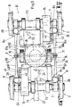
- the undercarriage 1 according to FIGS. 1 and 2, as shown an engine contains one on two wheelsets 2 and 3 supported bogie frame 4, on which over a central spring arrangement 5 a vehicle body 6 is supported.
- the wheelsets 2 and 3, each one Wheelset axle 7 and two wheels 8 connected to it in a rotationally fixed manner have over two each between the wheels 8 one of the axles 7 mounted guide devices 10 and a coupling device 11 with one another Vertical axis H pivotally coupled.
- the Guide devices 10 are also over Holding devices, as shown, each one Pendulum support 12, in the vehicle's longitudinal and transverse directions suspended on the vehicle body 6 or against supported this. At least one of the Guide devices 10, as shown of the wheelset 2 is with the vehicle body 6 via a Device 13 for transmitting tensile and braking forces coupled.
- the wheel sets 2 and 3 are each with a drive motor 14 provided with a spur gear 15 with the relevant wheelset axle 7 is connected by gearing.
- the guide devices 10 are each by the interconnected housing of the drive motor 14 and the spur gear 15 formed, which about Tatzlageranrangungen with one on the concerned Axle 7 mounted support tube 16 to a rigid Unit are connected.
- the pendulum supports 12 are as Anti-roll supports designed for the vehicle body 6 and in Vehicle longitudinal and transverse directions offset against each other on the guide devices 10 and each on one Vehicle body 6 provided articulation point 9 movable, as shown by elastic Intermediate pieces 19 made of a rubber-like material, articulated. Correspondingly, roll movements of the vehicle body 6 restricted about a longitudinal axis become.
- the coupling device 11 contains two each of one of the Guide devices 10 in the longitudinal direction of the chassis against the transverse center plane E of the undercarriage 1 protrudes, Drawbar-like connecting parts 17 and 18, which in the Chassis or bogie center can be swiveled to move are hinged together.
- Drawbar-like connecting parts 17 and 18, which in the Chassis or bogie center can be swiveled to move are hinged together.
- the guide devices 10 with each other in opposite directions deflectably coupled the axles 7 each in essentially radial to one to be traversed Track bends are adjustable.
- the connecting parts 17 and 18 can be shown via a ball joint 20 or, according to another version, in a simpler one Joint arrangement via elastic intermediate pieces from one rubber-like material interact.
- the device 13 for transmitting train and Braking forces include one compared to the wheelset 2 in Traverse of the vehicle can be offset 21 in the form of a wishbone with one against the Gear set 2 pointing connecting part 22 on a Support tube 16 attached pin 23 projecting downward is articulated, and two at the ends of the Traverse 21 articulated, orientable against the wheelset 2 Steering lever 24.
- the free ends of the steering lever 24 are for Linkage to two adjacent to the wheelset 2 Driver pin 25 determines which one after each Connection part of the vehicle body 6 above are attached, the distance between them Driver pin 25 is larger than the distance between the articulation points of the steering levers 24 on the crossmember 21.
- the arrangement of the driver pin 25 and the steering lever 24 can be chosen so that the chassis 1 in the middle of the chassis, in the area of the vertical axis H virtual pivot point, which is compared to the Vehicle body 6 does not perform a longitudinal displacement.
- a significant advantage of the described device 13 consists of the fact that they are outside the chassis 1 in an easily accessible area of the vehicle can be, in which sufficient installation space for Is available and one for the initiation of Traction forces convenient attachment to the vehicle body 6 is possible.
- the one relieved of the weight of the drive devices Bogie frame 4 can be in a particularly simple, lightweight construction, as shown as an H-shaped Supporting structure, which are two arranged within the track width of the wheel sets 2 and 3 Side member 26 and a central connecting them Cross member 27 has.
- the side members 26 are with their Ends over at least in the longitudinal direction of the chassis compliant spring elements 28, as shown Layered rubber springs, each between the wheels 8 of the concerned wheel set 2 or 3 arranged inner Support parts of the chassis 1, in the illustrated Execution on the housing parts of the Guide devices 10 arranged consoles 30, supported. Accordingly, a particularly simple, space-saving support arrangement can be achieved, via which the Support structure without additional axle bearings on the Wheelset axles 7 can be supported.
- the Spring arrangement 5 for supporting the vehicle body 6 is in the central area of the chassis 1 on a Cross member 27 trained support section 31 attached.
- the Side members 26 and the cross member 27 are as shown, each with a torsion-resistant, box-shaped cross-section.
- a corresponding cross member 27 with a T-shaped Cross section can also be provided, the one torsionally soft Allows connection between the longitudinal beams 26.
- a closed frame can be provided.
- the Spring arrangement 5 a support plate 19 and an air spring 32, which via a support ring 33, a support element 34 in Form of an annular rubber layer spring and a Axial bearing 35 on the support section 31 of the cross member 27 around the vertical axis H is rotatably supported.
- This central, rotatably mounted spring assembly 5 allows relatively large, largely unobstructed unscrewing movements of the Chassis 1 relative to the vehicle body 6 about the vertical axis H, with the chassis 1 being only advantageously small Apply restoring forces.
- the air spring 32 is in only by vertical support forces and if necessary, lateral forces are loaded, as they are disadvantageous Stresses on the air spring 32 by torsional forces can be avoided.
- support structure for the Vehicle body 6 is a particularly compact design of the Undercarriage 1 achievable with the outside of the wheel disks neither supporting and / or bearing parts nor parts of the Brake system are arranged.
- the illustration 1 and 2 can between the wheelsets 2 and 3 two each at a short distance above the Upper rail edges S arranged magnetic rail brakes 36 be provided, which each have holding rods 37 on two Brackets 38 are attached, each on the outside of the relevant side member 26 are attached.
- the Wheelsets 2 and 3 can also each with one within the Track width arranged gear brake in the form of a of the guide device 10 in question Brake unit 40 may be provided, which for Interaction with a brake disc 41 is determined which is shown on one of the housing of the Helical gear 15 projecting pinion shaft 42 of the Drive motor 14 is attached.
- the arrangement enables easy installation and removal of the Drive device.
- the motor / gear units can e.g. along with the motor disc brake down get extended.
- the between the bogie frame 4 and the Guide devices 10 arranged spring elements 28th result in a relatively hard in the vertical direction, in Flexible longitudinal and transverse direction Primary suspension, which relative movements of the wheel sets 2 and 3 compared to the bogie frame 4 in the sense of a at least approximately radial adjustment of the Wheelset axles 7 when passing through a curved track and when exiting the track curve, due to the Restoring force of the elastically deformed spring elements 28, a return of the axles 7 each in one normal position parallel to each other permitted. It is favorable loading of the spring elements 28 achievable, which corresponding deflections predominantly in the longitudinal direction, and only relatively small deflections in Experience transverse direction.
- the wheelsets 2 and 3 can also have at least one active or passive adjustment device in the sense of Setting and described above Reset movements of the axles 7 adjustable be coupled. Accordingly, the automatic Radial adjustment of wheel sets 2 and 3 supports and thus an improvement in the driving behavior of the chassis 1 when cornering, especially when driving Curvy routes with tight curve radii, achieved become.
- two corresponding, arranged below the longitudinal beams 26 active Adjusting devices 43 are provided, each having a piston / cylinder unit 44 included, the cylinder on relevant longitudinal member 26, e.g. in Movable articulated transverse direction, and as shown is connected to a rod 45, which at the with the Wheelset 2 coupled console 30 articulated is, and the piston via a piston rod 46 on the with the wheel set 3 coupled console 30 movable is articulated.
- the cylinder chambers of the two piston / cylinder units 44 can via two control lines 47 and 48 connected crosswise and via a Control device 50 to a source, not shown a pneumatic or hydraulic pressure medium be connected.
- the cylinder spaces of the piston / cylinder units 44 each in the opposite sense either via the control line 47 or via the Control line 48 can be pressurized so that the wheel sets 2 and 3 each between the Straight ahead corresponding normal position and two opposite displacement positions by one Wheel center axis adjustable and lockable are led.
- a Air spring or any other control element e.g. an electromechanical actuator can be provided.
- the described arrangement enables a passive, automatic setting with overlaid active Control of the axles 7, which, for example Failure of the control device 50, through which Restoring forces of the spring elements 28 each in the neutral normal position can be returned.
- Such adjustment devices are in particular from Advantage for vehicles to drive on track systems with tight curve radii.
- chassis 61 is as a frameless Support arrangement for the vehicle body 6 is formed.
- the each from the drive motor 14 and the gear transmission 15 formed drive units of the wheel sets 2 and 3 with one between the casings of the two Drive motors 14 arranged central support member 62 to connected to a rigid support structure 63, which two within the track width of wheel sets 2 and 3 arranged guide devices 65 and 65a on the Wheelset axles 7 is supported.
- the guiding devices 65 and 65a each contain two on both sides of the Support structure 63 arranged on the wheelset axles 7 stored and by these against the transverse central plane E of Chassis 61 pointing trailing arms 66 and 67 or 66a and 67a, which over a in the transverse central plane E arranged coupling device 68 with each other in the longitudinal direction of the chassis are flexibly coupled.
- the coupling device 68 contains one on the support part 62 rotatably mounted, transversely arranged coupling shaft 70 with connection parts 71 attached in a rotationally fixed manner and 72, the one on the connecting part 71 on the one Side of the chassis 61 arranged trailing arms 66 and 66a above or below the axis of rotation of the coupling shaft 70 are articulated and on the other connection part 72 the other side of the chassis 61 opposite arranged trailing arms 67 and 67a in opposite directions, each are articulated below or above the axis of rotation.
- the wheel sets 2 and 3 are over the Coupling device 68 can be deflected in opposite directions with one another coupled, the wheelset axles 7 each essentially radial to a track to be traversed are adjustable.
- the support structure 63 is on the housings of the Drive motor 14 and the spur gear 15 attached consoles 64 on four spring elements 28 supported, each on one of the trailing arms 66 and 67 and 66a and 67a are arranged.
- the correspondingly full Suspended drive units are with wheelsets 2 and 3 each coupled via a cardan shaft 73, which essentially non-reactive, each from the Deflection of the support structure 63 and from the Deflections of the wheelset 2 or 3 resulting Relative movements of the axle set 7 allows.
- the described arrangement also allows a particularly simple, compact design of the chassis 61, which is relatively few, favorably used Has parts and which, compared to previous ones Versions, a considerable weight saving guaranteed.
- the support structure 63 is a Anti-roll device 74 with the vehicle body 6 coupled, the spring arrangement 5 and that Thrust bearing 35 supported on the central support member 62 is.
- the anti-roll device 74 contains an Carrying part 62 mounted, arranged transversely Torsion bar 75 with torsion-proof at both ends attached, pointing in a longitudinal direction of the chassis Steering levers 76 and two on both sides of the support member 62 arranged pendulum supports 12, which on the steering levers 76th and can be swiveled on the vehicle body 6 so that it can move are articulated.
- the Torsion bar 75, the steering lever 76 and the pendulum supports 12 By appropriate dimensioning of the Torsion bar 75, the steering lever 76 and the pendulum supports 12 and by choosing the distances between them The roll stiffness between the Optimize chassis 61 and vehicle body 6.
- the device 13 or a other device for transmission of the train and Braking forces, e.g. a pull / push rod, on the housing of the Drive motor 14 be articulate
- the rail vehicle according to Figure 6 as shown three-part tram vehicle, contains two exterior Vehicle parts 81 and 83, which have a middle Vehicle part 82 articulated with each other and with this is connected via a bellows 84.
- the Vehicle boxes 6 of the outer vehicle parts 81 and 83 are with their outer end parts, as above described, each on an engine 1, and with their inner end portions on the middle vehicle part 82 supported, the vehicle body 6 on two of Drive devices free wheel sets 85 and 86 can be supported. These can, as shown smaller wheel diameters than drive gear sets 2 and 3 exhibit.
- the Floor part of the vehicle only in the over Power units 1 lying, relatively short End sections A executed in high-floor construction and can in one over most of the vehicle length continuous, central length section B in Low-floor construction. This is inside the vehicle an advantageous low Space available.
- the chassis contains two sets of wheels, each over two mounted on one of the axles Guide devices and a coupling device are coupled to each other in opposite directions, and one arranged within the track width of the wheel sets Supporting structure on which the vehicle body has a central spring arrangement is supported.
- the Supporting structure e.g. a bogie frame is about each compliant at least in the longitudinal direction of the chassis Spring elements arranged between the wheels, inner support parts supported on the Guide devices are formed.
- the Guiding devices are via a holding device, e.g. Pendulum supports and / or a device for Transfer of tensile and braking forces with the Vehicle body coupled to move in the transverse direction.
- the Chassis is especially for rail vehicles Driving on winding routes with tight curve radii suitable.
Landscapes
- Engineering & Computer Science (AREA)
- Mechanical Engineering (AREA)
- Chemical & Material Sciences (AREA)
- Combustion & Propulsion (AREA)
- Transportation (AREA)
- Vehicle Body Suspensions (AREA)
- Vehicle Interior And Exterior Ornaments, Soundproofing, And Insulation (AREA)
- Handcart (AREA)
- Platform Screen Doors And Railroad Systems (AREA)
Abstract
Description
- Fig.1
- ein erfindungsgemäss ausgebildetes Fahrwerk eines Schienentriebfahrzeuges in einem Längsschnitt entsprechend der Linie I - I in Fig.2,
- Fig.2
- das Fahrwerk nach Fig.1 in einer Draufsicht,
- Fig.3
- eine Einzelheit des Fahrwerks in einem Teillängsschnitt entsprechend der Linie III - III in Fig.2,
- Fig.4
- ein erfindungsgemäss ausgebildetes Fahrwerk eines Schienentriebfahrzeuges nach einer anderen Ausführungsform, in einem Längsschnitt entsprechend der Linie IV - IV in Fig.5,
- Fig.5
- das Fahrwerk nach Fig.4 in einer Draufsicht, und
- Fig.6
- ein Schienenfahrzeug mit erfindungsgemäss ausgebildeten Fahrwerken in einer Seitenansicht.
Claims (15)
- Fahrwerk für Schienenfahrzeuge, mit zwei Radsätzen (2, 3), welche über zwei je zwischen deren Rädern (8) auf einer der Radsatzachsen (7) gelagerte Führungsvorrichtungen 10; 65, 65a) und eine Koppelvorrichtung (11; 68) miteinander gegensinnig auslenkbar, je im wesentlichen radial zu einem jeweils zu durchfahrenden Gleisbogen einstellbar gekoppelt sind, und mit einer mit den Radsatzachsen (7) koppelbaren Traganordnung, welche zur Aufnahme einer Federanordnung (5) zum Abstützen des Fahrzeugkastens (6) eingerichtet ist, wobei mindestens einer der Radsätze (2, 3) über eine Halteeinrichtung und/oder eine Vorrichtung (13) zum Uebertragen von Zug- und Bremskräften mit dem Fahrzeugkasten (6) koppelbar ist,
dadurch gekennzeichnet, dass als Traganordnung für den Fahrzeugkasten (6) eine innerhalb der Spurweite der Radsätze (2, 3) angeordnete Tragkonstruktion vorgesehen ist, welche über je zumindest in Fahrwerk-Längsrichtung nachgiebige Federelemente (28) auf je zwischen den Rädern (8) des betreffenden Radsatzes (2, 3) angeordneten, inneren Stützteilen des Fahrwerks (1, 61) abgestützt ist. - Fahrwerk nach Anspruch 1, bei welchem die Federanordnung (5) zum Abstützen des Fahrzeugkastens (6) auf einer in einem zentralen Bereich des Fahrwerks (1, 61) positionierbaren Tragpartie (31, 62) der Tragkonstruktion angebracht ist.
- Fahrwerk nach Anspruch 2, bei welchem die Federanordnung (5) mindestens eine Luftfeder (32) oder ein hydraulisches oder hydropneumatisches Federelement enthält und über ein um eine vertikale Hochachse (H) drehbares Stützelement (34) auf der Tragpartie (31, 62) der Tragkonstruktion abgestützt ist.
- Fahrwerk nach Anspruch 3, bei welchem das Stützelement (34) über ein Axiallager (35) auf der Tragpartie (31, 62) abgestützt ist.
- Fahrwerk nach einem der vorangehenden Ansprüche, bei welchem die Stützteile für die die Tragkonstruktion abstützenden Federelemente (28) je mit der auf der betreffenden Radsatzachse (7) gelagerten Führungsvorrichtung (10; 65) verbunden oder an dieser ausgebildet sind.
- Fahrwerk nach einem der vorangehenden Ansprüche, bei welchem die Tragkonstruktion in Form eines Drehgestellrahmens (4) ausgeführt ist.
- Fahrwerk nach einem der Ansprüche 1 bis 5, bei welchem die Führungsvorrichtungen (65, 65a) je zwei beidseits der Tragkonstruktion (63) angeordnete, auf der Radsatzachse (7) gelagerte und gegen eine Quermittelebene (E) des Fahrwerks (61) weisende Längslenker (66, 67 bzw. 66a, 67a) enthalten und die Koppelvorrichtung (68) eine querliegend angeordnete, in der Tragkonstruktion (63) drehbar gelagerte Koppelwelle (70) mit an deren beiden Enden drehfest angebrachten Anschlussteilen (71 und 72) enthält, an denen die auf der einen Seite des Fahrwerks (61) angeordneten Längslenker (66, 66a) je oberhalb bzw. unterhalb der Drehachse der Koppelwelle (70) angelenkt sind und die auf der anderen Seite des Fahrwerks (61) angeordneten Längslenker (67, 67a) gegensinnig, je unterhalb bzw. oberhalb der Drehachse angelenkt sind.
- Fahrwerk nach Anspruch 7, bei welchem die Federelemente (28) zum Abstützen der Tragkonstruktion (63) je auf einem der Längslenker (66, 66a, 67, 67a) angebracht sind.
- Fahrwerk nach einem der vorangehenden Ansprüche, bei welchem die Halteeinrichtung mindestens zwei je an einem Fahrwerkteil (17, 18; 62) und am Fahrzeugkasten (6) anlenkbare, in Fahrwerk-Querrichtung gegeneinander versetzt angeordnete Wankstützelemente (12) enthält.
- Fahrwerk nach einem der vorangehenden Ansprüche, mit mindestens einer aktiven oder passiven Stellvorrichtung (43), welche mit mindestens einer der Führungsvorrichtungen (10; 65) koppelbar ist und über welche auf die Führungsvorrichtung (10; 65) bestimmte Einstellbewegungen je entsprechend einer zumindest annähernd radialen Einstellung und/oder einer entsprechenden Rückstellung der Radsatzachsen (7) übertragbar sind.
- Fahrwerk nach einem der vorangehenden Ansprüche, bei welchem mindestens einer der Radsätze (2, 3) mit einer Antriebseinrichtung (14, 15) gekoppelt ist.
- Fahrwerk nach Anspruch 11, bei welchem mindestens ein Teil der Antriebseinrichtung (14, 15) in einem Gehäuse angeordnet ist, welches über eine Lageranordnung (16) auf der Radsatzachse (7) abgestützt und als Führungsvorrichtung (10) für den Radsatz (2, 3) ausgebildet ist.
- Fahrwerk nach einem der Ansprüche 7 bis 11, mit zwei je einem der Radsätze (2, 3) zugeordneten Antriebseinrichtungen (14, 15), deren Gehäuse miteinander starr verbunden und als rahmenlose Tragkonstruktion (63) ausgebildet sind, an der die zum Abstützen des Fahrzeugkastens (6) bestimmte Federanordnung (5) angebracht ist.
- Schienenfahrzeug, insbesondere Strassenbahnfahrzeug, mit mindestens einem Fahrzeugkasten (6) und mindestens einem Fahrwerk (1, 61) nach einem der Ansprüche 1 bis 13.
- Schienenfahrzeug nach Anspruch 14, bei welchem die Vorrichtung (13) zum Uebertragen der Zug- und Bremskräfte eine gegenüber dem Fahrwerk (1; 61) in einer Fahrzeuglängsrichtung versetzt positionierbare Traverse (21) mit einem gegen den benachbarten Radsatz (2) weisenden, an einem Teil der Führungsvorrichtung (10) oder der Tragkonstruktion (63) anlenkbaren Verbindungsteil (22) und zwei an den Enden der Traverse (21) und am Fahrzeugkasten (6) anlenkbare, von der Traverse (21) gegen den benachbarten Radsatz (2) orientierbare Lenkhebel (24) enthält, wobei die diesen zugeordneten Anlenkstellen (25) am Fahrzeugkasten (6) in einem Abstand voneinander angeordnet sind, der grösser ist als der Abstand zwischen den entsprechenden Anlenkstellen an der Traverse (21).
Priority Applications (3)
| Application Number | Priority Date | Filing Date | Title |
|---|---|---|---|
| DE59811276T DE59811276D1 (de) | 1998-01-14 | 1998-01-14 | Fahrwerk für Schienenfahrzeuge und Schienenfahrzeug mit mindestens einem derartigen Fahrwerk |
| EP98810015A EP0930210B1 (de) | 1998-01-14 | 1998-01-14 | Fahrwerk für Schienenfahrzeuge und Schienenfahrzeug mit mindestens einem derartigen Fahrwerk |
| AT98810015T ATE265345T1 (de) | 1998-01-14 | 1998-01-14 | Fahrwerk für schienenfahrzeuge und schienenfahrzeug mit mindestens einem derartigen fahrwerk |
Applications Claiming Priority (1)
| Application Number | Priority Date | Filing Date | Title |
|---|---|---|---|
| EP98810015A EP0930210B1 (de) | 1998-01-14 | 1998-01-14 | Fahrwerk für Schienenfahrzeuge und Schienenfahrzeug mit mindestens einem derartigen Fahrwerk |
Publications (2)
| Publication Number | Publication Date |
|---|---|
| EP0930210A1 true EP0930210A1 (de) | 1999-07-21 |
| EP0930210B1 EP0930210B1 (de) | 2004-04-28 |
Family
ID=8235892
Family Applications (1)
| Application Number | Title | Priority Date | Filing Date |
|---|---|---|---|
| EP98810015A Expired - Lifetime EP0930210B1 (de) | 1998-01-14 | 1998-01-14 | Fahrwerk für Schienenfahrzeuge und Schienenfahrzeug mit mindestens einem derartigen Fahrwerk |
Country Status (3)
| Country | Link |
|---|---|
| EP (1) | EP0930210B1 (de) |
| AT (1) | ATE265345T1 (de) |
| DE (1) | DE59811276D1 (de) |
Cited By (5)
| Publication number | Priority date | Publication date | Assignee | Title |
|---|---|---|---|---|
| RU2364536C1 (ru) * | 2006-12-18 | 2009-08-20 | Гмб Гляйсбаумеханик Бранденбург/Х. Гмбх | Ходовая часть рельсового транспортного средства, оборудованного, по меньшей мере, одной машиной для механической обработки рельсов |
| WO2012123438A1 (en) * | 2011-03-15 | 2012-09-20 | Bombardier Transportation Gmbh | Integrated drive assembly for a rail vehicle |
| WO2018166582A1 (de) * | 2017-03-14 | 2018-09-20 | Siemens Ag Österreich | Fahrwerk für schienenfahrzeuge |
| RU2704637C1 (ru) * | 2018-10-01 | 2019-10-30 | Федеральное государственное бюджетное образовательное учреждение высшего образования Иркутский государственный университет путей сообщения (ФГБОУ ВО ИрГУПС) | Способ регулирования уровня колебания в подвесках тягового двигателя электровоза и устройство для его осуществления |
| CN112533814A (zh) * | 2018-03-27 | 2021-03-19 | 西门子交通奥地利有限责任公司 | 用于轨道车辆的行驶机构 |
Citations (6)
| Publication number | Priority date | Publication date | Assignee | Title |
|---|---|---|---|---|
| DE1057162B (de) * | 1955-07-21 | 1959-05-14 | Eisen & Stahlind Ag | Rahmen- und quertraegerloses Drehgestell, insbesondere Triebdrehgestell, fuer Schienenfahrzeuge |
| US4398468A (en) * | 1980-06-16 | 1983-08-16 | Rockwell International Corporation | Railway propulsion system suspension |
| EP0143540A2 (de) * | 1983-11-25 | 1985-06-05 | U T D C Inc. | Angetriebenes Eisenbahn-Drehgestell |
| EP0165752A2 (de) * | 1984-06-21 | 1985-12-27 | Railway Engineering Associates, Inc. | Selbststeuernde Drehgestelle |
| EP0313188A2 (de) * | 1987-07-28 | 1989-04-26 | Utdc Inc. | Lenkerverbindung für die Längssteuerung der Achseninnenjoche von Eisenbahndrehgestellen |
| EP0649782A1 (de) | 1993-10-21 | 1995-04-26 | SLM Schweizerische Lokomotiv- und Maschinenfabrik AG | Schienenfahrzeug und Fahrwerk für ein derartiges Fahrzeug |
-
1998
- 1998-01-14 EP EP98810015A patent/EP0930210B1/de not_active Expired - Lifetime
- 1998-01-14 AT AT98810015T patent/ATE265345T1/de not_active IP Right Cessation
- 1998-01-14 DE DE59811276T patent/DE59811276D1/de not_active Expired - Fee Related
Patent Citations (6)
| Publication number | Priority date | Publication date | Assignee | Title |
|---|---|---|---|---|
| DE1057162B (de) * | 1955-07-21 | 1959-05-14 | Eisen & Stahlind Ag | Rahmen- und quertraegerloses Drehgestell, insbesondere Triebdrehgestell, fuer Schienenfahrzeuge |
| US4398468A (en) * | 1980-06-16 | 1983-08-16 | Rockwell International Corporation | Railway propulsion system suspension |
| EP0143540A2 (de) * | 1983-11-25 | 1985-06-05 | U T D C Inc. | Angetriebenes Eisenbahn-Drehgestell |
| EP0165752A2 (de) * | 1984-06-21 | 1985-12-27 | Railway Engineering Associates, Inc. | Selbststeuernde Drehgestelle |
| EP0313188A2 (de) * | 1987-07-28 | 1989-04-26 | Utdc Inc. | Lenkerverbindung für die Längssteuerung der Achseninnenjoche von Eisenbahndrehgestellen |
| EP0649782A1 (de) | 1993-10-21 | 1995-04-26 | SLM Schweizerische Lokomotiv- und Maschinenfabrik AG | Schienenfahrzeug und Fahrwerk für ein derartiges Fahrzeug |
Cited By (8)
| Publication number | Priority date | Publication date | Assignee | Title |
|---|---|---|---|---|
| RU2364536C1 (ru) * | 2006-12-18 | 2009-08-20 | Гмб Гляйсбаумеханик Бранденбург/Х. Гмбх | Ходовая часть рельсового транспортного средства, оборудованного, по меньшей мере, одной машиной для механической обработки рельсов |
| WO2012123438A1 (en) * | 2011-03-15 | 2012-09-20 | Bombardier Transportation Gmbh | Integrated drive assembly for a rail vehicle |
| WO2018166582A1 (de) * | 2017-03-14 | 2018-09-20 | Siemens Ag Österreich | Fahrwerk für schienenfahrzeuge |
| US11400961B2 (en) | 2017-03-14 | 2022-08-02 | Siemens Mobility Austria Gmbh | Chassis for rail vehicle |
| CN112533814A (zh) * | 2018-03-27 | 2021-03-19 | 西门子交通奥地利有限责任公司 | 用于轨道车辆的行驶机构 |
| CN112533814B (zh) * | 2018-03-27 | 2023-11-07 | 西门子交通奥地利有限责任公司 | 用于轨道车辆的行驶机构 |
| US12030532B2 (en) | 2018-03-27 | 2024-07-09 | Siemens Mobility Austria Gmbh | Running gear for a rail vehicle |
| RU2704637C1 (ru) * | 2018-10-01 | 2019-10-30 | Федеральное государственное бюджетное образовательное учреждение высшего образования Иркутский государственный университет путей сообщения (ФГБОУ ВО ИрГУПС) | Способ регулирования уровня колебания в подвесках тягового двигателя электровоза и устройство для его осуществления |
Also Published As
| Publication number | Publication date |
|---|---|
| DE59811276D1 (de) | 2004-06-03 |
| EP0930210B1 (de) | 2004-04-28 |
| ATE265345T1 (de) | 2004-05-15 |
Similar Documents
| Publication | Publication Date | Title |
|---|---|---|
| DE1605826C3 (de) | Drehgestell für Eisenbahnwagen mit mindestens zwei Radsätzen | |
| DE4140126C2 (de) | Laufwerk für Schienenfahrzeuge | |
| DE3111087C2 (de) | Einzelradanordnung für Eisenbahnfahrzeuge | |
| EP1915283B1 (de) | Fahrzeug mit wankstützen | |
| EP0420801B1 (de) | Schienenfahrzeug | |
| CH671930A5 (de) | ||
| EP0649782B1 (de) | Schienenfahrzeug und Fahrwerk für ein derartiges Fahrzeug | |
| EP0598353B1 (de) | Fahrwerk für Niederflurbahnen | |
| EP0838386B1 (de) | Schienenfahrzeug mit mindenstens einem Fahrwerk und Fahrwerk für ein derartiges Fahrzeug | |
| DE19507021C2 (de) | Fahrwerk für Eisenbahnfahrzeuge | |
| DE19703701C2 (de) | Zweiachsiges Fahrwerk für schienengebundene Transportsysteme | |
| DE2024484C3 (de) | Achslastausgleich eines Schienentriebfahrzeuges | |
| EP0930210B1 (de) | Fahrwerk für Schienenfahrzeuge und Schienenfahrzeug mit mindestens einem derartigen Fahrwerk | |
| DE696273C (de) | Dreiachsiges Deichsellaufgestell fuer Schienenfahrzeuge | |
| EP0439573B1 (de) | Fahrgestell für niederflurwagen | |
| EP2158114B1 (de) | Schienenfahrzeug mit einstufiger federung | |
| AT398557B (de) | Fahrwerk für ein schienenfahrzeug, insbesondere niederflurfahrzeug | |
| EP0678436B1 (de) | Selbstlenkendes dreiachsiges Laufwerk für ein Schienenfahrzeug | |
| DE4422109C2 (de) | Kuppelbare Fahrwerkanordnung zum Tragen und Querneigen eines Wagenkastens | |
| AT256165B (de) | Schienenfahrzeug mit tiefliegender Plattform | |
| CH684075A5 (de) | Drehgestell. | |
| DE9302772U1 (de) | Kleinraddrehgestell mit selbst-steuernden Radsätzen für Schienenfahrzeuge | |
| DE29720120U1 (de) | Fahrwerk für Schienenfahrzeuge | |
| DE1605113C (de) | Niederflurwagen | |
| DE1455165C (de) | Mehrachsiges Schienentriebfahrzeug |
Legal Events
| Date | Code | Title | Description |
|---|---|---|---|
| PUAI | Public reference made under article 153(3) epc to a published international application that has entered the european phase |
Free format text: ORIGINAL CODE: 0009012 |
|
| AK | Designated contracting states |
Kind code of ref document: A1 Designated state(s): AT CH DE FR GB IT LI SE |
|
| AX | Request for extension of the european patent |
Free format text: AL;LT;LV;MK;RO;SI |
|
| RAP1 | Party data changed (applicant data changed or rights of an application transferred) |
Owner name: DAIMLERCHRYSLER AG |
|
| AKX | Designation fees paid | ||
| REG | Reference to a national code |
Ref country code: DE Ref legal event code: 8566 |
|
| 17P | Request for examination filed |
Effective date: 20000426 |
|
| RBV | Designated contracting states (corrected) |
Designated state(s): AT CH DE FR GB IT LI SE |
|
| RAP1 | Party data changed (applicant data changed or rights of an application transferred) |
Owner name: DAIMLERCHRYSLER RAIL SYSTEMS GMBH |
|
| 17Q | First examination report despatched |
Effective date: 20020611 |
|
| GRAH | Despatch of communication of intention to grant a patent |
Free format text: ORIGINAL CODE: EPIDOS IGRA |
|
| GRAS | Grant fee paid |
Free format text: ORIGINAL CODE: EPIDOSNIGR3 |
|
| RAP1 | Party data changed (applicant data changed or rights of an application transferred) |
Owner name: BOMBARDIER TRANSPORTATION GMBH |
|
| GRAA | (expected) grant |
Free format text: ORIGINAL CODE: 0009210 |
|
| AK | Designated contracting states |
Kind code of ref document: B1 Designated state(s): AT CH DE FR GB IT LI SE |
|
| REG | Reference to a national code |
Ref country code: GB Ref legal event code: FG4D Free format text: NOT ENGLISH |
|
| REG | Reference to a national code |
Ref country code: CH Ref legal event code: EP |
|
| REF | Corresponds to: |
Ref document number: 59811276 Country of ref document: DE Date of ref document: 20040603 Kind code of ref document: P |
|
| REG | Reference to a national code |
Ref country code: SE Ref legal event code: TRGR |
|
| GBT | Gb: translation of ep patent filed (gb section 77(6)(a)/1977) |
Effective date: 20040812 |
|
| ET | Fr: translation filed | ||
| PLBE | No opposition filed within time limit |
Free format text: ORIGINAL CODE: 0009261 |
|
| STAA | Information on the status of an ep patent application or granted ep patent |
Free format text: STATUS: NO OPPOSITION FILED WITHIN TIME LIMIT |
|
| 26N | No opposition filed |
Effective date: 20050131 |
|
| PGFP | Annual fee paid to national office [announced via postgrant information from national office to epo] |
Ref country code: DE Payment date: 20070110 Year of fee payment: 10 |
|
| PGFP | Annual fee paid to national office [announced via postgrant information from national office to epo] |
Ref country code: SE Payment date: 20070111 Year of fee payment: 10 Ref country code: AT Payment date: 20070111 Year of fee payment: 10 |
|
| PGFP | Annual fee paid to national office [announced via postgrant information from national office to epo] |
Ref country code: CH Payment date: 20070112 Year of fee payment: 10 |
|
| PGFP | Annual fee paid to national office [announced via postgrant information from national office to epo] |
Ref country code: GB Payment date: 20070119 Year of fee payment: 10 |
|
| PGFP | Annual fee paid to national office [announced via postgrant information from national office to epo] |
Ref country code: IT Payment date: 20070614 Year of fee payment: 10 |
|
| PGFP | Annual fee paid to national office [announced via postgrant information from national office to epo] |
Ref country code: FR Payment date: 20070111 Year of fee payment: 10 |
|
| REG | Reference to a national code |
Ref country code: CH Ref legal event code: PL |
|
| EUG | Se: european patent has lapsed | ||
| GBPC | Gb: european patent ceased through non-payment of renewal fee |
Effective date: 20080114 |
|
| PG25 | Lapsed in a contracting state [announced via postgrant information from national office to epo] |
Ref country code: LI Free format text: LAPSE BECAUSE OF NON-PAYMENT OF DUE FEES Effective date: 20080131 Ref country code: DE Free format text: LAPSE BECAUSE OF NON-PAYMENT OF DUE FEES Effective date: 20080801 Ref country code: CH Free format text: LAPSE BECAUSE OF NON-PAYMENT OF DUE FEES Effective date: 20080131 |
|
| PG25 | Lapsed in a contracting state [announced via postgrant information from national office to epo] |
Ref country code: AT Free format text: LAPSE BECAUSE OF NON-PAYMENT OF DUE FEES Effective date: 20080114 |
|
| REG | Reference to a national code |
Ref country code: FR Ref legal event code: ST Effective date: 20081029 |
|
| PG25 | Lapsed in a contracting state [announced via postgrant information from national office to epo] |
Ref country code: GB Free format text: LAPSE BECAUSE OF NON-PAYMENT OF DUE FEES Effective date: 20080114 |
|
| PG25 | Lapsed in a contracting state [announced via postgrant information from national office to epo] |
Ref country code: SE Free format text: LAPSE BECAUSE OF NON-PAYMENT OF DUE FEES Effective date: 20080115 |
|
| PG25 | Lapsed in a contracting state [announced via postgrant information from national office to epo] |
Ref country code: FR Free format text: LAPSE BECAUSE OF NON-PAYMENT OF DUE FEES Effective date: 20080131 |
|
| PG25 | Lapsed in a contracting state [announced via postgrant information from national office to epo] |
Ref country code: IT Free format text: LAPSE BECAUSE OF NON-PAYMENT OF DUE FEES Effective date: 20080114 |