EP0930409B1 - Dispositif de réception pour un système de commande à distance et procédé d'actionnement d'un système de commande à distance - Google Patents
Dispositif de réception pour un système de commande à distance et procédé d'actionnement d'un système de commande à distance Download PDFInfo
- Publication number
- EP0930409B1 EP0930409B1 EP99100617A EP99100617A EP0930409B1 EP 0930409 B1 EP0930409 B1 EP 0930409B1 EP 99100617 A EP99100617 A EP 99100617A EP 99100617 A EP99100617 A EP 99100617A EP 0930409 B1 EP0930409 B1 EP 0930409B1
- Authority
- EP
- European Patent Office
- Prior art keywords
- receiver
- signal
- response threshold
- receiving device
- remote control
- Prior art date
- Legal status (The legal status is an assumption and is not a legal conclusion. Google has not performed a legal analysis and makes no representation as to the accuracy of the status listed.)
- Expired - Lifetime
Links
- 238000000034 method Methods 0.000 title claims description 10
- 230000004044 response Effects 0.000 claims description 43
- 238000001514 detection method Methods 0.000 claims description 5
- 230000008859 change Effects 0.000 claims description 4
- 230000003321 amplification Effects 0.000 claims description 2
- 238000003199 nucleic acid amplification method Methods 0.000 claims description 2
- 230000005540 biological transmission Effects 0.000 description 6
- 230000035945 sensitivity Effects 0.000 description 3
- 230000004913 activation Effects 0.000 description 2
- 238000013016 damping Methods 0.000 description 2
- 230000003247 decreasing effect Effects 0.000 description 2
- 230000009849 deactivation Effects 0.000 description 1
- 230000007423 decrease Effects 0.000 description 1
- 230000007812 deficiency Effects 0.000 description 1
- 238000005516 engineering process Methods 0.000 description 1
- 230000006266 hibernation Effects 0.000 description 1
- 230000003014 reinforcing effect Effects 0.000 description 1
- 230000001960 triggered effect Effects 0.000 description 1
Images
Classifications
-
- B—PERFORMING OPERATIONS; TRANSPORTING
- B60—VEHICLES IN GENERAL
- B60J—WINDOWS, WINDSCREENS, NON-FIXED ROOFS, DOORS, OR SIMILAR DEVICES FOR VEHICLES; REMOVABLE EXTERNAL PROTECTIVE COVERINGS SPECIALLY ADAPTED FOR VEHICLES
- B60J7/00—Non-fixed roofs; Roofs with movable panels, e.g. rotary sunroofs
- B60J7/02—Non-fixed roofs; Roofs with movable panels, e.g. rotary sunroofs of sliding type, e.g. comprising guide shoes
- B60J7/04—Non-fixed roofs; Roofs with movable panels, e.g. rotary sunroofs of sliding type, e.g. comprising guide shoes with rigid plate-like element or elements, e.g. open roofs with harmonica-type folding rigid panels
- B60J7/057—Driving or actuating arrangements e.g. manually operated levers or knobs
- B60J7/0573—Driving or actuating arrangements e.g. manually operated levers or knobs power driven arrangements, e.g. electrical
-
- G—PHYSICS
- G07—CHECKING-DEVICES
- G07C—TIME OR ATTENDANCE REGISTERS; REGISTERING OR INDICATING THE WORKING OF MACHINES; GENERATING RANDOM NUMBERS; VOTING OR LOTTERY APPARATUS; ARRANGEMENTS, SYSTEMS OR APPARATUS FOR CHECKING NOT PROVIDED FOR ELSEWHERE
- G07C9/00—Individual registration on entry or exit
- G07C9/00174—Electronically operated locks; Circuits therefor; Nonmechanical keys therefor, e.g. passive or active electrical keys or other data carriers without mechanical keys
- G07C9/00182—Electronically operated locks; Circuits therefor; Nonmechanical keys therefor, e.g. passive or active electrical keys or other data carriers without mechanical keys operated with unidirectional data transmission between data carrier and locks
-
- G—PHYSICS
- G07—CHECKING-DEVICES
- G07C—TIME OR ATTENDANCE REGISTERS; REGISTERING OR INDICATING THE WORKING OF MACHINES; GENERATING RANDOM NUMBERS; VOTING OR LOTTERY APPARATUS; ARRANGEMENTS, SYSTEMS OR APPARATUS FOR CHECKING NOT PROVIDED FOR ELSEWHERE
- G07C9/00—Individual registration on entry or exit
- G07C9/00174—Electronically operated locks; Circuits therefor; Nonmechanical keys therefor, e.g. passive or active electrical keys or other data carriers without mechanical keys
- G07C9/00309—Electronically operated locks; Circuits therefor; Nonmechanical keys therefor, e.g. passive or active electrical keys or other data carriers without mechanical keys operated with bidirectional data transmission between data carrier and locks
- G07C2009/00507—Electronically operated locks; Circuits therefor; Nonmechanical keys therefor, e.g. passive or active electrical keys or other data carriers without mechanical keys operated with bidirectional data transmission between data carrier and locks keyless data carrier having more than one function
-
- G—PHYSICS
- G07—CHECKING-DEVICES
- G07C—TIME OR ATTENDANCE REGISTERS; REGISTERING OR INDICATING THE WORKING OF MACHINES; GENERATING RANDOM NUMBERS; VOTING OR LOTTERY APPARATUS; ARRANGEMENTS, SYSTEMS OR APPARATUS FOR CHECKING NOT PROVIDED FOR ELSEWHERE
- G07C9/00—Individual registration on entry or exit
- G07C9/00174—Electronically operated locks; Circuits therefor; Nonmechanical keys therefor, e.g. passive or active electrical keys or other data carriers without mechanical keys
- G07C2009/00753—Electronically operated locks; Circuits therefor; Nonmechanical keys therefor, e.g. passive or active electrical keys or other data carriers without mechanical keys operated by active electrical keys
- G07C2009/00769—Electronically operated locks; Circuits therefor; Nonmechanical keys therefor, e.g. passive or active electrical keys or other data carriers without mechanical keys operated by active electrical keys with data transmission performed by wireless means
Definitions
- the invention relates to a receiving device of a remote control system, especially for the locking system of a motor vehicle, according to the preamble of Claim 1 and a method for operating a remote control system.
- DE-OS 33 41 900 is a remote control system for locking and unlocking Security systems known in vehicles.
- the remote control system consists of a receiving device, which is housed in the vehicle, and a signal transmitter with own energy supply. By pressing the signal transmitter from this coded signals sent out in the direction of the receiving device.
- the receiving device receives the signals, compares them with a saved pattern and presses Matching the signal pattern of a security system.
- the signals generated by the signal transmitter are said to be changeable Transmission energy can be sent out. By increasing the transmission energy with increasing duration of operation should be achieved on the one hand that an actuation of the Security system with the given distance between vehicle and transmitter lowest possible transmission energy takes place in order to listen to the transmission signal To complicate foreign persons.
- the battery should be as little as possible be claimed.
- the transmitter's increasing transmit power can be achieved even under difficult Reception conditions, such as B. icy windows, still a function of Remote control system is ensured.
- a remote control device Triggering of various functions in a motor vehicle disclosed, where different functions are different Reception ranges are assigned. It is in the idle state Receiver set to maximum range, that is his Response threshold is low. If a signal is received, so depending on the content of the first part of this signal Range reduced by increasing the response threshold to then the second part, which triggers the actual function to receive and evaluate the signal.
- WO-9211431-A1 describes a remote-controlled vehicle locking system in which to guarantee a constant range the sensitivity of the receiver or continuously readjust the transmission power of the transmitter become.
- US-5420568 is also a wireless vehicle locking system known at which the response threshold of Receiver can be changed from the outside using a switch can.
- This response threshold defines the range, within whose unlocking of the vehicle is permitted. On Locking is carried out over the entire range.
- the Threshold is set during remote control operation not changed automatically.
- the receiving device In modern locking systems with a remote control system that is Transmission device usually housed in the vehicle key.
- the receiving device usually contains an intelligent one Electronics that is capable of multiple actuators head for.
- Such a receiving device monitors, controls and controls functions as diverse as the central locking the doors, the anti-theft alarm system, the interior lighting, the window regulators and the sunroof.
- closing the windows and the sunroof for safety reasons e.g. Pinch protection
- the receiving device cannot recognize the reasons for which signals are no longer present. This can be desired by the operator, but it can also be due to too low a signal level. The latter occurs e.g. B.
- this is done by Means for changing the response threshold of the receiving device reached which after the detection of a signal lower the response threshold above the response threshold and increase again after no signal.
- the receiving device By the receiving device according to the invention or the inventive Procedure is achieved that a comfort function like closing the windows or the sunroof is maintained even when the signal level by moving the transmitter or enlarging the Distance between Sending and receiving device reduced. A faltering or uneven Operation due to falling signal levels is largely ruled out, since decreasing Signal level due to a reduced response threshold of the receiving device a wide range can be compensated.
- the change in the response threshold of the receiving device can take the form of a Switching over a damping or changeable by a control signal Reinforcing member take place.
- the Change the response threshold a comparator to compare the level of the received signal provided with a default value.
- the control signal for that Attenuator or gain element or the default value for the comparator expediently by one contained in the receiving device Microprocessor provided.
- the receiving device can in particular a radio receiving device or an infrared receiving device act.
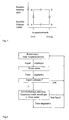
- the hysteresis of the response threshold of the receiving device for a Comfort function such as closing the windows or sunroof shown.
- a first higher Response threshold This is synonymous with a low sensitivity of the Receiving device or with a reduced range of the transmitting device.
- the System is inactive (state A, idle state). Will increase with this Response threshold the signal coming from the transmitter is recognized as correct, the comfort function is activated (state B).
- the Response threshold lowered state C, sensitivity or range increased), see above that even with decreasing signal level by movement of the operator and the comfort function is executed without interference.
- the comfort function is only activated as long as the operator has activated the transmitter, i.e. as long as the corresponding key is pressed. If the transmitter is deactivated (release of the button), the Comfort function in the position reached and is deactivated (state D). The Response threshold is increased again (state A, initial state).
- the activation / Deactivation of the comfort function and switching of the response threshold be carried out simultaneously or in a different order. For example can start from the idle state after detecting a signal above the response threshold activates the comfort function and the Response threshold can be lowered. Starting from the same hibernation it is also possible after detecting a signal above the response threshold first lower the response threshold and then close the comfort function activate (reversal of direction in Fig. 1).
- the flowchart of which is shown in FIG. 2 it is provided that after detection of a signal above the response threshold of Receiving device first a timer is started. Is after the timer has expired the signal is still on, the comfort function is activated and the response threshold of the Receiving device changed as described. With activation of the comfort function a timer can be started again, after which the convenience function is ended, regardless of whether the input signal is still present. the period this second timer is chosen to be sufficiently large that the Comfort function can be completed. However, the comfort function is in everyone Case interrupted when no signal is present at the receiving device.
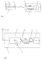
- Fig. 3 is a complete remote control system for motor vehicles in principle shown. It contains a transmitting device 1, which is usually in the key head is integrated.
- the transmitting device 1 contains an energy supply in the form of a Battery 2, the code generator 3 and transmitter 4.
- the receiving device 5 contains next to the receiver 6, a microprocessor 7. From the transmitter 4 to Pressing a button (not shown) emits signals from the receiver 6 detected and forwarded to the microprocessor 7.
- the signals are in the Microprocessor processed.
- different actuators possibly required additional electronic components such as amplifier stages are part of the stand of technology and are familiar to the person skilled in the art.
- FIG. 4 An embodiment of the switchover of the Response threshold of the receiving device 5 is shown in Fig. 4. This is before Receiver 6 and microprocessor 7 a switching device 8 with a Attenuator 9 provided.
- the attenuator 9 is a switch 10, the is controlled by the microprocessor 7 in the idle state of the remote control system switched between antenna 11 and receiver 6 and thus sets the Response threshold of the receiving device 5 up.
- the response threshold using an intermediate Antenna 11 and receiver 6 switched amplifier instead of the attenuator 9 to change.
- the amplifier is then only in the active state of the comfort function switched on to lower the response threshold.
- a switchable Amplifier or attenuator is also an amplifier or an attenuator directly controllable amplification or damping possible.
- a comparator in the receiving device provided that compares the level of the input signal with a preset value. Is the level of the input signal or a signal derived from it above the Default value, the comfort function is activated and the response threshold is activated by a lower comparator default value.
- the comparator can both be integrated in the receiver 6 and in the microprocessor 7. However, too a separate comparator between receiver 6 and microprocessor 7 possible.
- the respective default value for the comparator depends on the operating state of the The receiving device is expediently specified by the microprocessor 7.
Landscapes
- Engineering & Computer Science (AREA)
- Mechanical Engineering (AREA)
- Computer Networks & Wireless Communication (AREA)
- Physics & Mathematics (AREA)
- General Physics & Mathematics (AREA)
- Lock And Its Accessories (AREA)
- Selective Calling Equipment (AREA)
Claims (9)
- Dispositif de réception (5) d'un système de commande à distance, en particulier pour le système de fermeture d'un véhicule automobile, qui est conçu pour la réception de signaux d'un dispositif d'émission (1) associé et qui, lorsque les niveaux des signaux appliqués sont situés au-dessus de son seuil de réaction, commande un ou plusieurs actionneurs, et qui contient par ailleurs des moyens de modification du seuil de réaction du dispositif de réception (5), caractérisé en ce que les moyens de modification du seuil de réaction abaissent le niveau de réaction après la détection d'un signal et augmentent de nouveau le seuil de réaction en cas de disparition du signal.
- Dispositif de réception (5) selon la revendication 1, caractérisé en ce que pour modifier le seuil de réaction, le dispositif de réception contient un organe d'atténuation (9) ou d'amplification qui peut être modifié par un signal de commande.
- Dispositif de réception (5) selon la revendication 1, caractérisé en ce que le dispositif de réception contient un comparateur qui compare le niveau du signal reçu ou d'un signal qui en est dérivé à une valeur prédéterminée.
- Dispositif de réception (5) selon l'une des revendications précédentes, caractérisé par des moyens de modification décalée dans le temps du seuil de réception après la détection du signal.
- Dispositif de réception (5) selon l'une des revendications précédentes, caractérisé en ce qu'il s'agit d'un dispositif de réception radio.
- Dispositif de réception (5) selon l'une des revendications précédentes, caractérisé en ce qu'en plus d'un dispositif de fermeture des portes, le dispositif de réception actionne également un dispositif de fermeture des fenêtres et/ou d'un toit ouvrant.
- Dispositif de réception (5) selon l'une des revendications précédentes, caractérisé en ce qu'en plus du récepteur de signaux proprement dit, il contient un microprocesseur (7) qui délivre un signal de sortie pour un ou plusieurs actionneurs tant qu'un signal situé au-dessus du seuil de réaction est détecté.
- Procédé pour l'actionnement d'un système de commande à distance, en particulier pour des véhicules automobiles, constitué d'un dispositif d'émission (1) ainsi que d'un dispositif de réception (5) à seuil de réaction commutable, qui contient les étapes de procédé suivantes:abaissement du seuil de réaction du dispositif de réception (5) après qu'un signal du dispositif d'émission (1) a été détecté etrelèvement du seuil de réaction du dispositif de réception (5) après disparition d'un signal.
- Procédé selon la revendication 8, caractérisé en ce que la réduction du seuil de réaction du dispositif de réception (5) après la détection du signal s'effectue après une temporisation.
Applications Claiming Priority (2)
| Application Number | Priority Date | Filing Date | Title |
|---|---|---|---|
| DE19801885A DE19801885A1 (de) | 1998-01-20 | 1998-01-20 | Empfangseinrichtung eines Fernbedienungssystems und Verfahren zum Betreiben eines Fernbedienungssystems |
| DE19801885 | 1998-01-20 |
Publications (2)
| Publication Number | Publication Date |
|---|---|
| EP0930409A1 EP0930409A1 (fr) | 1999-07-21 |
| EP0930409B1 true EP0930409B1 (fr) | 2004-03-24 |
Family
ID=7855084
Family Applications (1)
| Application Number | Title | Priority Date | Filing Date |
|---|---|---|---|
| EP99100617A Expired - Lifetime EP0930409B1 (fr) | 1998-01-20 | 1999-01-14 | Dispositif de réception pour un système de commande à distance et procédé d'actionnement d'un système de commande à distance |
Country Status (3)
| Country | Link |
|---|---|
| US (1) | US6472998B1 (fr) |
| EP (1) | EP0930409B1 (fr) |
| DE (2) | DE19801885A1 (fr) |
Families Citing this family (7)
| Publication number | Priority date | Publication date | Assignee | Title |
|---|---|---|---|---|
| DE10004213A1 (de) * | 2000-02-01 | 2001-08-02 | Daimler Chrysler Ag | Verfahren zur Steuerung der Bewegung von mindestens einem elektromotorisch bewegten Teil eines motorangetriebenen Fahrzeugs |
| DE10058678C2 (de) * | 2000-11-25 | 2002-11-14 | Integrated Electronic Systems Sys Consulting Gmbh | Verfahren zum Betrieb einer Funkfernsteuerungsanlage |
| US20050233771A1 (en) * | 2002-07-16 | 2005-10-20 | Shoot & Talk Ltd. | Directional dialing cellular telephone protocol and appurtenances for use therewith |
| FR2844388B1 (fr) * | 2002-09-05 | 2005-05-27 | Somfy | Procede d'inhibition des touches du clavier d'un emetteur d'ordres |
| FR2867503B1 (fr) * | 2004-03-15 | 2006-06-02 | Peugeot Citroen Automobiles Sa | Procede de commande a distance du verrouillage et du deverrouillage d'un vehicule automobile |
| US7519400B2 (en) * | 2005-05-27 | 2009-04-14 | Dei Headquarters, Inc. | Multi-modulation remote control communication system |
| CN115733504B (zh) * | 2021-08-27 | 2025-11-14 | 华为技术有限公司 | 通信方法与装置 |
Family Cites Families (11)
| Publication number | Priority date | Publication date | Assignee | Title |
|---|---|---|---|---|
| DE3341900A1 (de) | 1983-11-19 | 1985-05-30 | Robert Bosch Gmbh, 7000 Stuttgart | Schaltungsanordnung zur ver- und entriegelung von sicherheitsanlagen durch fernbedienung |
| JPS6237479A (ja) * | 1985-08-12 | 1987-02-18 | 日産自動車株式会社 | 無線式施解錠制御装置 |
| EP0306598A3 (fr) * | 1987-09-08 | 1989-08-23 | Clifford Electronics, Inc. | Systèmes d'accès avec commande à distance électroniquement programmables |
| US5648764A (en) * | 1989-08-09 | 1997-07-15 | Fujitsu Ten Limited | Apparatus for remotely controlling a door locking state and theft prevention alarm state of an automobile |
| US5717387A (en) * | 1990-01-19 | 1998-02-10 | Prince Corporation | Remote vehicle programming system |
| DE9102747U1 (de) * | 1990-12-21 | 1991-05-23 | Siemens AG, 8000 München | Verriegelungssystem, z.B. Zentralverriegelungssystem eines Kfz |
| DE59105724D1 (de) * | 1991-01-25 | 1995-07-20 | Siemens Ag | Verfahren zur Reduzierung der Verlustleistung bei Einrichtungen zur berührungslosen Daten-und Energieübertragung sowie Anordnung zur Durchführung des Verfahrens. |
| DE4124181C2 (de) * | 1991-07-20 | 1997-01-23 | Daimler Benz Ag | Verfahren zum Betreiben eines Handsenders zum Steuern von Fahrzeugfunktionen |
| US5420568A (en) * | 1992-03-31 | 1995-05-30 | Kansei Corporation | Wireless door locking and unlocking system for motor vehicles having theft alarm device |
| FR2706934B1 (fr) * | 1993-06-21 | 1995-10-13 | Valeo Electronique | |
| DE4409167C1 (de) * | 1994-03-17 | 1995-06-29 | Siemens Ag | Schlüssellose Zugangskontrolleinrichtung |
-
1998
- 1998-01-20 DE DE19801885A patent/DE19801885A1/de not_active Ceased
-
1999
- 1999-01-14 EP EP99100617A patent/EP0930409B1/fr not_active Expired - Lifetime
- 1999-01-14 DE DE59908922T patent/DE59908922D1/de not_active Expired - Lifetime
- 1999-01-15 US US09/232,036 patent/US6472998B1/en not_active Expired - Fee Related
Also Published As
| Publication number | Publication date |
|---|---|
| DE59908922D1 (de) | 2004-04-29 |
| US6472998B1 (en) | 2002-10-29 |
| DE19801885A1 (de) | 1999-07-22 |
| EP0930409A1 (fr) | 1999-07-21 |
Similar Documents
| Publication | Publication Date | Title |
|---|---|---|
| DE69925651T2 (de) | Verriegelungschutzsystem mit intelligentem Schlüssel | |
| DE102006016737B4 (de) | Verfahren und Vorrichtung zum Konfigurieren verschiedener Betriebsmodi in einem passiven Schließsystem | |
| DE69431975T2 (de) | Fernbedienungssystem mit mehreren funktionellen Reichweiten ausgewählt auf Grund verschiedener Detektionsschwellen | |
| DE102006013202B4 (de) | System und Verfahren zum Steuern einer Fahrzeugtür | |
| DE102008060082B4 (de) | RFID-Transponder mit verbesserter Weckmusterdetektion und Verfahren | |
| DE102005056910B4 (de) | Integriertes System zum passiven Zugang und zum schlüssellosen Zugang per Fernsteuerung | |
| DE102006035651B4 (de) | Steuersystem für eine Fahrzeugausstattung und dazugehöriges Verfahren | |
| DE4329697C2 (de) | Fernsteuerbare Zugangskontrolleinrichtung | |
| DE102011075853B4 (de) | Innen-/Außen-Feststellung für tragbare Sendeeinrichtung mit geringer Latenz | |
| DE60009830T2 (de) | Mit einem handfreien Zugangs- und/oder Startsystem ausgerüstetes Kraftfahrzeug | |
| DE10019442C2 (de) | Sicherheitssystem zum Verhindern des unbefugten Startens des Motors eines Fahrzeugs | |
| DE19508276A1 (de) | Lernfähige Sende-Empfängereinrichtung | |
| EP4370386B1 (fr) | Procédé d'autorisation d'accès à un véhicule automobile au moyen d'un dispositif d'identification électronique mobile | |
| WO1992011431A1 (fr) | Systeme de fermeture, par exemple systeme centralise de verrouillage de vehicules a moteur | |
| DE102010001652A1 (de) | Automatische Erfassung des Entfernens von einem Fahrzeug | |
| DE102007020802A1 (de) | Fahrzeug-Steuersystem | |
| DE112017000755B4 (de) | Elektronisches schlüsselsystem | |
| EP1447775A2 (fr) | Dispositif de verrouillage électronique | |
| EP0744843A2 (fr) | Système de communication de données | |
| DE102006042682B4 (de) | Steuersystem für eine Fahrzeugvorrichtung, fahrzeugseitige Einheit und tragbare Vorrichtung | |
| EP3064404B1 (fr) | Interruption fonctionnelle d'un systeme d'acces de vehicule | |
| DE10031468B4 (de) | Fernbedienung | |
| EP0930409A1 (fr) | Dispositif de réception pour un système de commande à distance et procédé d'actionnement d'un système de commande à distance | |
| EP3444151A1 (fr) | Système de sécurité destiné à l'activation d'une fonction relative à la sécurité dans un véhicule | |
| DE112020001669B4 (de) | Drahtloses Kommunikationssystem |
Legal Events
| Date | Code | Title | Description |
|---|---|---|---|
| PUAI | Public reference made under article 153(3) epc to a published international application that has entered the european phase |
Free format text: ORIGINAL CODE: 0009012 |
|
| AK | Designated contracting states |
Kind code of ref document: A1 Designated state(s): DE FR GB |
|
| AX | Request for extension of the european patent |
Free format text: AL;LT;LV;MK;RO;SI |
|
| 17P | Request for examination filed |
Effective date: 19990721 |
|
| AKX | Designation fees paid |
Free format text: DE FR GB |
|
| RAP1 | Party data changed (applicant data changed or rights of an application transferred) |
Owner name: SIEMENS AKTIENGESELLSCHAFT |
|
| 17Q | First examination report despatched |
Effective date: 20030226 |
|
| GRAP | Despatch of communication of intention to grant a patent |
Free format text: ORIGINAL CODE: EPIDOSNIGR1 |
|
| GRAS | Grant fee paid |
Free format text: ORIGINAL CODE: EPIDOSNIGR3 |
|
| GRAA | (expected) grant |
Free format text: ORIGINAL CODE: 0009210 |
|
| AK | Designated contracting states |
Kind code of ref document: B1 Designated state(s): DE FR GB |
|
| REG | Reference to a national code |
Ref country code: GB Ref legal event code: FG4D Free format text: NOT ENGLISH |
|
| GBT | Gb: translation of ep patent filed (gb section 77(6)(a)/1977) |
Effective date: 20040401 |
|
| REF | Corresponds to: |
Ref document number: 59908922 Country of ref document: DE Date of ref document: 20040429 Kind code of ref document: P |
|
| ET | Fr: translation filed | ||
| PLBE | No opposition filed within time limit |
Free format text: ORIGINAL CODE: 0009261 |
|
| STAA | Information on the status of an ep patent application or granted ep patent |
Free format text: STATUS: NO OPPOSITION FILED WITHIN TIME LIMIT |
|
| 26N | No opposition filed |
Effective date: 20041228 |
|
| PGFP | Annual fee paid to national office [announced via postgrant information from national office to epo] |
Ref country code: GB Payment date: 20090122 Year of fee payment: 11 |
|
| GBPC | Gb: european patent ceased through non-payment of renewal fee |
Effective date: 20100114 |
|
| PG25 | Lapsed in a contracting state [announced via postgrant information from national office to epo] |
Ref country code: GB Free format text: LAPSE BECAUSE OF NON-PAYMENT OF DUE FEES Effective date: 20100114 |
|
| REG | Reference to a national code |
Ref country code: FR Ref legal event code: TP |
|
| PGFP | Annual fee paid to national office [announced via postgrant information from national office to epo] |
Ref country code: FR Payment date: 20130213 Year of fee payment: 15 Ref country code: DE Payment date: 20130131 Year of fee payment: 15 |
|
| REG | Reference to a national code |
Ref country code: DE Ref legal event code: R119 Ref document number: 59908922 Country of ref document: DE |
|
| REG | Reference to a national code |
Ref country code: DE Ref legal event code: R119 Ref document number: 59908922 Country of ref document: DE Effective date: 20140801 |
|
| PG25 | Lapsed in a contracting state [announced via postgrant information from national office to epo] |
Ref country code: DE Free format text: LAPSE BECAUSE OF NON-PAYMENT OF DUE FEES Effective date: 20140801 |
|
| REG | Reference to a national code |
Ref country code: FR Ref legal event code: ST Effective date: 20140930 |
|
| PG25 | Lapsed in a contracting state [announced via postgrant information from national office to epo] |
Ref country code: FR Free format text: LAPSE BECAUSE OF NON-PAYMENT OF DUE FEES Effective date: 20140131 |