EP0930412A1 - Türscharnier mit Feststeller, insbesondere für ein Kraftfahrzeug - Google Patents
Türscharnier mit Feststeller, insbesondere für ein Kraftfahrzeug Download PDFInfo
- Publication number
- EP0930412A1 EP0930412A1 EP99440007A EP99440007A EP0930412A1 EP 0930412 A1 EP0930412 A1 EP 0930412A1 EP 99440007 A EP99440007 A EP 99440007A EP 99440007 A EP99440007 A EP 99440007A EP 0930412 A1 EP0930412 A1 EP 0930412A1
- Authority
- EP
- European Patent Office
- Prior art keywords
- door
- housing
- hinge according
- knuckle
- cam
- Prior art date
- Legal status (The legal status is an assumption and is not a legal conclusion. Google has not performed a legal analysis and makes no representation as to the accuracy of the status listed.)
- Withdrawn
Links
- 230000007246 mechanism Effects 0.000 claims abstract description 26
- 238000007789 sealing Methods 0.000 claims description 11
- 230000008878 coupling Effects 0.000 claims description 8
- 238000010168 coupling process Methods 0.000 claims description 8
- 238000005859 coupling reaction Methods 0.000 claims description 8
- 230000000295 complement effect Effects 0.000 claims description 6
- 230000002093 peripheral effect Effects 0.000 claims description 5
- 239000011324 bead Substances 0.000 claims description 3
- 230000008901 benefit Effects 0.000 description 3
- 239000002184 metal Substances 0.000 description 3
- 238000010422 painting Methods 0.000 description 3
- 230000000694 effects Effects 0.000 description 2
- 238000001962 electrophoresis Methods 0.000 description 2
- 230000008595 infiltration Effects 0.000 description 2
- 238000001764 infiltration Methods 0.000 description 2
- 230000014759 maintenance of location Effects 0.000 description 2
- 239000000463 material Substances 0.000 description 2
- 238000005096 rolling process Methods 0.000 description 2
- XLYOFNOQVPJJNP-UHFFFAOYSA-N water Substances O XLYOFNOQVPJJNP-UHFFFAOYSA-N 0.000 description 2
- 230000005540 biological transmission Effects 0.000 description 1
- 239000013013 elastic material Substances 0.000 description 1
- 235000021189 garnishes Nutrition 0.000 description 1
- KJFBVJALEQWJBS-XUXIUFHCSA-N maribavir Chemical compound CC(C)NC1=NC2=CC(Cl)=C(Cl)C=C2N1[C@H]1O[C@@H](CO)[C@H](O)[C@@H]1O KJFBVJALEQWJBS-XUXIUFHCSA-N 0.000 description 1
- 230000004048 modification Effects 0.000 description 1
- 238000012986 modification Methods 0.000 description 1
- 238000000926 separation method Methods 0.000 description 1
Images


Classifications
-
- E—FIXED CONSTRUCTIONS
- E05—LOCKS; KEYS; WINDOW OR DOOR FITTINGS; SAFES
- E05D—HINGES OR SUSPENSION DEVICES FOR DOORS, WINDOWS OR WINGS
- E05D11/00—Additional features or accessories of hinges
- E05D11/10—Devices for preventing movement between relatively-movable hinge parts
- E05D11/1028—Devices for preventing movement between relatively-movable hinge parts for maintaining the hinge in two or more positions, e.g. intermediate or fully open
- E05D11/105—Devices for preventing movement between relatively-movable hinge parts for maintaining the hinge in two or more positions, e.g. intermediate or fully open the maintaining means acting perpendicularly to the pivot axis
- E05D11/1057—Devices for preventing movement between relatively-movable hinge parts for maintaining the hinge in two or more positions, e.g. intermediate or fully open the maintaining means acting perpendicularly to the pivot axis specially adapted for vehicles
-
- E—FIXED CONSTRUCTIONS
- E05—LOCKS; KEYS; WINDOW OR DOOR FITTINGS; SAFES
- E05Y—INDEXING SCHEME ASSOCIATED WITH SUBCLASSES E05D AND E05F, RELATING TO CONSTRUCTION ELEMENTS, ELECTRIC CONTROL, POWER SUPPLY, POWER SIGNAL OR TRANSMISSION, USER INTERFACES, MOUNTING OR COUPLING, DETAILS, ACCESSORIES, AUXILIARY OPERATIONS NOT OTHERWISE PROVIDED FOR, APPLICATION THEREOF
- E05Y2900/00—Application of doors, windows, wings or fittings thereof
- E05Y2900/50—Application of doors, windows, wings or fittings thereof for vehicles
- E05Y2900/53—Type of wing
- E05Y2900/531—Doors
Definitions
- the present invention relates to a door hinge with retaining notch, in particular for a motor vehicle, this hinge comprising at least one foot knuckle and a door knuckle hinged to each other along a pivot axis, and a notch retaining mechanism, this mechanism comprising at least one lever carrying a roller integral with one of the knuckles, a cam provided with at least one retaining notch and integral with the other knuckle, and means for returning the cam towards the the sink.
- This type of hinge is known, for example, from publications WO-A-91/19876 and FR-A-2.722.233 by the same holder and includes a notch retention mechanism attached to either knuckle of the hinge.
- These known achievements require connecting members of the housing containing the retaining mechanism to one knuckles and connecting members of the lever or the cam to the other knuckle.
- These connecting members generate wear and tear on the surfaces in contact creating working games.
- These operating clearances significantly reduce hinge and retainer functions and are also a source of noise.
- the connecting members require a number of parts important to assemble, increasing the total cost of the hinge. Otherwise, the tightness of the housing containing the retaining mechanism is not optimal and, in in the case of a water inlet, the mechanism is irreversibly damaged. His replacement involves a significant labor cost.
- the object of the present invention is to produce a door hinge with retaining notch resistant and reliable over time, simple and inexpensive design, does not maintenance-free, compact and whose functions are integrated and optimized.
- the object of the invention is also to provide a hinge door that can be permanently mounted on the vehicle and can pass through different treatment and painting baths without any risk for the mechanism restrained.
- Yet another object of the invention is to be able to unhook the door that is to say, remove it and then put it back without any particular adjustment.
- the retaining notch door hinge as defined in preamble and characterized in that it comprises a housing arranged to receive said notch retention mechanism, this case incorporating one of the knuckles and the mechanism comprising said pin.
- the foot knuckle is advantageously coupled to the door knuckle by said pin ensuring a sealed connection with the latter, the pin passing through said housing and can be coupled directly to the lever carrying the roller.
- the lever consists of two parallel arms coupled at one end to said spindle by coupling means and said roller turn is disposed between them at their other end.
- the spindle is advantageously coupled securely to the hinge of the foot by coupling means comprising two complementary profiles and a fixation, one of the profiles corresponding to the specific shape of the dihedral, the other corresponding to the inverted shape of the dihedral.
- the spindle is mounted in the housing by at least one self-lubricating ring.
- the cam is pivotally mounted in said housing to one of its ends and is coupled to the return means at the other end.
- This cam preferably comprises a cam profile in which can be provided at the minus one retaining notch, each retaining notch defining an open position Door.
- the return means preferably include a spiral spring mounted in the housing, one of its ends driving the cam via a drive device and the other being fixed relative to the housing.
- the drive device may include a link, one end of which carries a stud solidly coupled to the spiral spring and the other carries a stud engaged in a light provided in the cam, the tenon being offset with respect to the stud.
- the housing can be made in one piece with the door knuckle or can be overmolded on the door knuckle.
- the door knuckle advantageously consists of a bracket provided a branch intended to be molded by said housing and having zones and another branch intended to be mounted on a vehicle door and having a flat bearing surface.
- the hinge may include indexing means of the door relative to the vehicle body, these means comprising a recess in said housing and a separate indexing part, arranged to be fixed on said door and provided with a lug intended to fit into said recess when the door is in position.
- the hinge has a cover arranged to cover the housing, the cover comprising sealing means provided at least on its inner peripheral edge.
- these sealing means may include at least one added O-ring, at least one removed seal or at least one bead integrated into said hood and forming a baffle.
- the door 2 of a motor vehicle 1 is generally pivotally coupled to the body 3 of a motor vehicle by two hinges: a lower hinge 10 and an upper hinge 20.
- the hinge lower 10 comprises in known manner a hinge 11 attached to the body 3 by screws passing through bores 11 'and a door knuckle 12 fixed to the door 2 by screws passing through 12 'bores, the two knuckles being coupled by a spindle 13 pivoting in a self-lubricated ring 14 and held between a retaining rings 15 and a screw 16.
- the upper hinge 20, which more precisely constitutes the object of the present invention and which will therefore be described in more detail, comprises a hinge 21 fixed to the body 3 by screws through bores 21 'and a door knuckle 22 fixed to door 2 by screws through bores 22 '.
- Door knuckle 22 comprises a hollow housing 30 intended to receive a notch retaining mechanism 31. Note that the housing 30 and the door knuckle 22 form one and the same room.
- the two knuckles 21, 22 are coupled by a pin 23 mounted in two self-lubricating rings 24 superimposed and separated by an O-ring 25 (shown in Figure 5). Of course, this pin can also be mounted in a single self-lubricated ring with or without the presence of an O-ring.
- Pin 23 is fixed, at its lower end 23a, to the foot knuckle 21 by means of coupling comprising two complementary V-shaped profiles respectively in projection and recess and a screw 26.
- the pin 23 passes through the housing 30 of the knuckle door 22 through a bore 27, in which the self-lubricated rings are mounted 24, and protrudes from the housing 30 by its upper end 23b which has a form called "Torx".
- the notch retainer 31 has a lever 32 formed of two arms parallel 32a and coupled to the upper end 23b of the pin 23 by means of a bore 32 'having a shape complementary to the so-called "Torx" shape of said upper end 23b and a circlip 33.
- This lever 32 has at its end free a rotating roller 34 mounted between the two parallel arms 32a by means of a small axis 35.
- the notch retaining mechanism 31 also includes a cam 36 of elongated and curved shape which is pivotally mounted around the axis of a screw 38 engaged in a bore 37 of the housing 30.
- the cam 36 comprises on the side of the lever 32 a cam profile defining at least one but in the example illustrated two notches retainer 39a, 39b, each notch defining a stable position for opening the door.
- This cam 36 is driven by a spring member and more particularly to a spring in a spiral 40 by means of a drive device consisting of a link 41.
- This link 41 has a first end fixed integrally to the part central of the spring 40 by a stud 42 provided with at least one lateral flat and a second end slidably mounted in a light 44 arranged in the cam 36 in which a pin 43 is engaged.
- the spiral spring 40 is fixed at its end free to a fixed stop 45 provided in the housing 30.
- This housing 30 is closed by a hood 46 in the shape of a bell, the walls of which cover the peripheral edge of said housing.
- This cover 46 is completed by members sealing which will be described later, to ensure perfect sealing of the housing.
- FIG. 2 shows the door 2 of a vehicle 1 in the closed position.
- the housing 30 of the notch retaining mechanism 31, integral with the door knuckle 22, is housed in the free space 4 existing between the body 3 and the door 2.
- the lever 32 integral with the foot knuckle 21 is located on one side of the housing 30, its rotating roller 34 not being in contact with the cam 36 which is returned by the spiral spring 40 in direction of said lever 32 by the pin 43.
- Figure 3 shows the door 2 in a semi-open position, or position parking.
- the housing 30, being integral with the door 2 has moved angularly with the door.
- the cam 36 which also moved by the same angular value, came into contact with the rotating roller 34 of the lever 32 remained fixed.
- the cam 36 Under the effect of the roller 34 rolling on the cam profile 39, the cam 36 has pivoted around the screw 38, compressing the spring 40 until the roller 34 meets the first notch retainer 39a defining the first stable opening position of door 2.
- Figure 4 shows the door 2 in a fully open position. Box 30 moved again with the door. During this movement, the cam 36 is also moved by the same angular value. Under the effect of the roller 34 rolling on the cam profile 39, the cam 36 has pivoted around the screw 38, compressing the spring 40 until the roller 34 meets the second retaining notch 39b defining the second stable opening position of door 2.
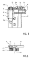
- Figure 5 shows in axial section the housing 30, the pin 23, the two self-lubricated rings 24, the O-ring 25, the lever 32, the roller 34 and the cam 36.
- the self-lubricating rings 24 provide rotational guidance of the housing 30 coupled to the door knuckle 22 around the spindle 23 coupled to the foot knuckle 21.
- the O-ring 25 ensures the tightness of the housing 30 relative to the external atmosphere to avoid in particular moisture infiltration.
- the lever 32 is coupled to the pin 23 by a so-called link "Torx" and carries at its free end the rotating roller 34 which cooperates with the cam 36. This roller 34 is sandwiched between the two parallel arms 32a forming said lever 32.
- This type of mounting which avoids the overhang, has the advantage of guaranteeing a precise height positioning of said roller, without floating and without risk of deflection due to the force undergone by the cam 36 under stress by the spring 40.
- the efforts are thus better balanced and transmitted more homogeneous to pin 23 at the so-called "Torx" link.
- Figure 6 shows in axial section the spiral spring 40, the cam 36 and the link 41.
- the link 41 is coupled on the one hand to the central part of the spring 40 by the stud 42 and on the other hand to the cam 36 by the stud 43 sliding in the light 44 formed in the cam 36.
- the lug 43 is offset from the center of the spring spiral 40 to be able to exert a resistant torque on the pivoting cam 36.
- the tenon 43 sliding in the light 44 ensures a balanced transmission of forces, without overhang and without deviation from the axes.
- FIGS. 7A, 7B and 7C represent the pin 23 alone, viewed from the front respectively, side view and in cross section at the end 23b of Torx shape.
- This Torx shape which is known, ensures perfect coupling, without play and without friction between the spindle 23 and the lever 32 allowing to support a very torque Student.
- the end 23a is coupled to the foot knuckle 21 by the coupling of two complementary V-shaped profiles, formed by two plane faces converging towards a common edge forming a dihedral, which also ensures a perfect connection, without play, without friction, therefore without wear and allows to support a very high torque.
- This coupling has the advantage of also ensuring self-centering of spindle 23 by relative to the hinge 21 and a self-centering of the housing 30 and therefore the door knuckle 21 relative to pin 23.
- FIGS. 8A, 8B and 8C represent three exemplary embodiments of the means sealing the cover 46 relative to the housing 30.
- the cover 46 has a shape bell and covers the entire housing 30 thus protecting the retaining mechanism 31 from any water infiltration. Nevertheless, a perfect seal must be ensured between the outer periphery of the housing 30 and the inner periphery of the cover 46.
- the cover 46 is made of sheet metal, its peripheral edge being slightly flared to receive an O-ring 47 ensuring its tightness with the periphery of the housing 30.
- the cover 46 is made of plastic, its edge inner device being biased and covered with a deposited seal 48 which ensures sealing with the housing 30 after mounting.
- the cover 46 is produced of rubber or other elastic material, its inner peripheral edge comprising beads 49 arranged to seal with the housing 30 after assembly.
- the hood 46 can be completed by fixing means such as an edge clipped under the lower periphery of the housing 30.
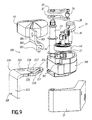
- FIGS 9 to 11 illustrate an alternative embodiment of the upper hinge 200 according to the invention in which we find the majority of the parts described previously and in particular the entire notch retainer mechanism 31. All of the identical parts have the same reference number and will not be described in new The only parts that differ are the housing 30 and the door knuckle 22 respectively referenced 300 and 220, which in this embodiment are produced in two separate parts and joined together by overmolding.
- the door knuckle 220 is made up of a metal bracket ensuring the rigidity of the hinge and comprising two branches 221 and 222 arranged at right angles, one 221 being intended to be molded by said housing and the other 222 being intended to be fixed by screwing on the vehicle door.
- the branch 221 has a shape substantially triangular and has three bores 223, 224 and 225 intended to receive respectively the spindle 23, the axis 38 of the cam 36 and the central axis of the spring 40.
- the branch 222 has a flat bearing surface 226 intended to bear on a corresponding door surface and has at least two oblong holes (not shown) to receive the fixing screws.
- the housing 300 is made of plastic and is molded onto the branch 221 corresponding to the knuckle of door 220.
- this branch 221 comprises a central recess 227 and a notched periphery 228 having the function of ensuring good plastic bonding to avoid any risk of separation even in high mechanical torque.
- the housing 300 additionally includes indexing means allowing to unhinge the easy to carry and put back in place without having to re-adjust in position.
- indexing means includes a recess 301 provided in said housing 300, arranged paaallel to the axis of the spindle 23 and having a section not circular, such as square or rectangular, as well as an indexing piece 302 separate, made of metal, comprising a lug 303, of cross section complementary to that of the recess 301 to fit into this recess.
- Indexing part 302 has a fixing lug 304 intended to be fixed to the vehicle door by a fixing screw through the hole 305.
- FIG. 11 illustrates the hinge 200, in which the door knuckle 220 and the indexing piece 302 are fixed on a door 2 of a vehicle, the lug 303 being fitted into the recess 301.
- the hinge 200 fitted with its notch retaining mechanism is fixed on the one hand to the body of a vehicle by the hinge pin 21 and on the other leaves on door 2 by door knuckle 220.
- door 2 is set to position relative to the body thanks to the oblong holes provided in the knuckle door 220 and fixing screws.
- Indexing part 302, the lug 303 of which is fitted into the recess 301, is also fixed to the door 2 by a fixing screw.
- the assembly thus mounted can pass into the cataphoresis baths.
- door 2 must be dismantled before it can be garnished. For this step, we remove the screws fixing the door knuckle 220. By lifting the door 2, the lug 303 comes out of its recess 301 and we can then completely remove the door 2 on which the part indexing 302 remains fixed.
- the dressing of door 2 When the dressing of door 2 is finished, it remains to reassemble it on the vehicle. For this, we position the door 2 so as to fit the lug 303 of the indexing part 302 in the recess 301 of the hinge 200 and to present the door relative to the knuckle of door 220 in plane support on its corresponding surface 226. Then, one fixes said door knuckle 220 by its two fixing screws without the need for reposition door 2 relative to the vehicle body, this positioning being provided by the indexing piece 302 and the planar bearing surface 226 of the knuckle door 220.
- the notch retaining mechanism integrates the function of the articulation of the door and thus allows to simplify the parts and reduce costs.
- this hinge allows you to quickly unhook a door and go back up without any particular adjustment, which is entirely advantageous from a point of view economical on current assembly lines.
Landscapes
- Engineering & Computer Science (AREA)
- Mechanical Engineering (AREA)
- Hinges (AREA)
Applications Claiming Priority (2)
| Application Number | Priority Date | Filing Date | Title |
|---|---|---|---|
| FR9800691 | 1998-01-20 | ||
| FR9800691A FR2773839B1 (fr) | 1998-01-20 | 1998-01-20 | Charniere de porte a cran de retenue, notamment pour un vehicule automobile |
Publications (1)
| Publication Number | Publication Date |
|---|---|
| EP0930412A1 true EP0930412A1 (de) | 1999-07-21 |
Family
ID=9522063
Family Applications (1)
| Application Number | Title | Priority Date | Filing Date |
|---|---|---|---|
| EP99440007A Withdrawn EP0930412A1 (de) | 1998-01-20 | 1999-01-20 | Türscharnier mit Feststeller, insbesondere für ein Kraftfahrzeug |
Country Status (2)
| Country | Link |
|---|---|
| EP (1) | EP0930412A1 (de) |
| FR (1) | FR2773839B1 (de) |
Cited By (4)
| Publication number | Priority date | Publication date | Assignee | Title |
|---|---|---|---|---|
| US7203996B2 (en) * | 2000-09-13 | 2007-04-17 | Friedr. Fingscheidt Gmbh | Hinge door arrester for vehicle doors |
| EP1788176A1 (de) * | 2005-11-22 | 2007-05-23 | Mgi Coutier | Türscharnier mit integriertem Türfeststeller |
| US9458653B2 (en) * | 2014-11-21 | 2016-10-04 | Nissan North America, Inc. | Check link structure |
| CN106545248A (zh) * | 2016-10-26 | 2017-03-29 | 神龙汽车有限公司 | 一种集成限位器的汽车车门铰链 |
Families Citing this family (4)
| Publication number | Priority date | Publication date | Assignee | Title |
|---|---|---|---|---|
| FR2864011B1 (fr) * | 2003-12-17 | 2006-02-17 | Coutier Moulage Gen Ind | Procede de fabrication de charnieres avec boitier, et boitier pour la mise en oeuvre de ce procede |
| FR2915504B1 (fr) * | 2007-04-24 | 2010-11-05 | Coutier Moulage Gen Ind | Charniere avec mecanisme d'arret integre pour porte de vehicule automobile. |
| DE202008015786U1 (de) | 2008-11-28 | 2009-02-19 | Edscha Ag | Kraftfahrzeugtürscharnier |
| FR2962149B1 (fr) | 2010-06-30 | 2013-04-26 | Coutier Moulage Gen Ind | Dispositif d'arret de porte pour vehicule automobile |
Citations (2)
| Publication number | Priority date | Publication date | Assignee | Title |
|---|---|---|---|---|
| US5018243A (en) * | 1990-10-12 | 1991-05-28 | Itt Corporation | Vehicle door hinge with compound roller structure |
| EP0531216A1 (de) * | 1991-09-05 | 1993-03-10 | Societe Financiere D'etude Et De Developpement Industriel Et Technologique | Türscharnier mit integriertem Türfeststeller, insbesondere für eine Fahrzeugtür |
Family Cites Families (2)
| Publication number | Priority date | Publication date | Assignee | Title |
|---|---|---|---|---|
| WO1991019876A1 (fr) | 1989-04-12 | 1991-12-26 | Mgi Coutier (S.A.) | Charniere a crans de retenue pour une porte, notamment d'un vehicule automobile |
| FR2722233B1 (fr) | 1994-07-07 | 1996-09-27 | Coutier Moulage Gen Ind | 1charniere de porte a cran de retenu2vehicule automobile |
-
1998
- 1998-01-20 FR FR9800691A patent/FR2773839B1/fr not_active Expired - Fee Related
-
1999
- 1999-01-20 EP EP99440007A patent/EP0930412A1/de not_active Withdrawn
Patent Citations (2)
| Publication number | Priority date | Publication date | Assignee | Title |
|---|---|---|---|---|
| US5018243A (en) * | 1990-10-12 | 1991-05-28 | Itt Corporation | Vehicle door hinge with compound roller structure |
| EP0531216A1 (de) * | 1991-09-05 | 1993-03-10 | Societe Financiere D'etude Et De Developpement Industriel Et Technologique | Türscharnier mit integriertem Türfeststeller, insbesondere für eine Fahrzeugtür |
Cited By (5)
| Publication number | Priority date | Publication date | Assignee | Title |
|---|---|---|---|---|
| US7203996B2 (en) * | 2000-09-13 | 2007-04-17 | Friedr. Fingscheidt Gmbh | Hinge door arrester for vehicle doors |
| EP1788176A1 (de) * | 2005-11-22 | 2007-05-23 | Mgi Coutier | Türscharnier mit integriertem Türfeststeller |
| FR2893658A1 (fr) * | 2005-11-22 | 2007-05-25 | Coutier Moulage Gen Ind | Charniere de porte avec arret de porte integre |
| US9458653B2 (en) * | 2014-11-21 | 2016-10-04 | Nissan North America, Inc. | Check link structure |
| CN106545248A (zh) * | 2016-10-26 | 2017-03-29 | 神龙汽车有限公司 | 一种集成限位器的汽车车门铰链 |
Also Published As
| Publication number | Publication date |
|---|---|
| FR2773839A1 (fr) | 1999-07-23 |
| FR2773839B1 (fr) | 2000-04-07 |
Similar Documents
| Publication | Publication Date | Title |
|---|---|---|
| FR2504075A1 (fr) | Retroviseur exterieur de vehicule | |
| FR2820375A1 (fr) | Dispositif de fixation pour accoudoir amovible et dispositif d'assise comportant un tel dispositif de fixation | |
| FR2920462A1 (fr) | Ouvrant arriere, ensemble d'ouvrants, vehicule automobile cet ouvrant ou cet ensemble et barre de toit de ce vehicule. | |
| EP0563032B1 (de) | Türscharnier mit haltevertiefungen, insbesondere für kraftfahrzeuge | |
| FR2811007A1 (fr) | Charniere avec arret de porte integre | |
| EP0060748B1 (de) | Festhalteeinrichtung, insbesondere für Fahrzeugtür | |
| EP0930412A1 (de) | Türscharnier mit Feststeller, insbesondere für ein Kraftfahrzeug | |
| EP3159225B1 (de) | Verbindungsvorrichtung für scheibenwischerarm | |
| WO2012131187A1 (fr) | Dispositif d'arrêt de porte pour portière de véhicule notamment automobile | |
| EP0443919B1 (de) | Scharnier mit integriertem Feststeller für Fahrzeugtüre oder andere Flügel | |
| EP2360339A1 (de) | Stellglied mit Arm für Fenster- oder Türflügel | |
| FR2764551A1 (fr) | Ensemble de lunette arriere ouvrante pour porte de coffre de vehicule automobile | |
| EP1126116A1 (de) | Scharniereinrichtung für Türflügel eines Kraftfahrzeuges | |
| FR2491402A1 (fr) | Pare-soleil, notamment pour vehicule automobile | |
| EP3604051B1 (de) | Einheit zum verbinden eines antriebsarms eines scheibenwischers mit einer motorwelle eines fahrzeugs | |
| FR3097892A1 (fr) | Capot de recouvrement pour un entraînement de porte ou de fenêtre | |
| FR2537928A3 (fr) | Portiere de vehicule automobile | |
| FR3105108A1 (fr) | Dispositif de fixation d’un élément d’étanchéité à un composant de véhicule | |
| EP0299856B1 (de) | Fahrzeughaubenaufhängung | |
| EP3156576B1 (de) | Fensterhebervorrichtung für ein kraftfahrzeug, entsprechende kraftfahrzeugtür und entsprechendes montageverfahren | |
| FR2779389A1 (fr) | Dispositif d'obturation d'une baie menagee dans la carrosserie d'un vehicule, a coulissement exterieur, et procede de fabrication et de montage correspondant | |
| EP0935271B1 (de) | Scharnierdeckel insbesonderes für Schalterabdeckung | |
| EP0845332A1 (de) | Vorrichtung zum Befestigen von Dichtungslippen | |
| WO2019202253A2 (fr) | Bague de fixation pour verrou | |
| WO2007135010A1 (fr) | Mecanisme d'essuyage comportant des moyens de blocage d'un arbre d'entrainement dans une position angulaire |
Legal Events
| Date | Code | Title | Description |
|---|---|---|---|
| PUAI | Public reference made under article 153(3) epc to a published international application that has entered the european phase |
Free format text: ORIGINAL CODE: 0009012 |
|
| AK | Designated contracting states |
Kind code of ref document: A1 Designated state(s): DE ES FR GB IT |
|
| AX | Request for extension of the european patent |
Free format text: AL;LT;LV;MK;RO;SI |
|
| 17P | Request for examination filed |
Effective date: 20000110 |
|
| AKX | Designation fees paid |
Free format text: DE ES FR GB IT |
|
| 17Q | First examination report despatched |
Effective date: 20010123 |
|
| STAA | Information on the status of an ep patent application or granted ep patent |
Free format text: STATUS: THE APPLICATION IS DEEMED TO BE WITHDRAWN |
|
| 18D | Application deemed to be withdrawn |
Effective date: 20010605 |