EP0930514A2 - Système et procédé pour déterminer la position d'un terminal mobile - Google Patents
Système et procédé pour déterminer la position d'un terminal mobile Download PDFInfo
- Publication number
- EP0930514A2 EP0930514A2 EP98124879A EP98124879A EP0930514A2 EP 0930514 A2 EP0930514 A2 EP 0930514A2 EP 98124879 A EP98124879 A EP 98124879A EP 98124879 A EP98124879 A EP 98124879A EP 0930514 A2 EP0930514 A2 EP 0930514A2
- Authority
- EP
- European Patent Office
- Prior art keywords
- mobile terminal
- field intensity
- received field
- repeater
- transmitter
- Prior art date
- Legal status (The legal status is an assumption and is not a legal conclusion. Google has not performed a legal analysis and makes no representation as to the accuracy of the status listed.)
- Ceased
Links
Images

Classifications
-
- H—ELECTRICITY
- H04—ELECTRIC COMMUNICATION TECHNIQUE
- H04W—WIRELESS COMMUNICATION NETWORKS
- H04W64/00—Locating users or terminals or network equipment for network management purposes, e.g. mobility management
-
- G—PHYSICS
- G01—MEASURING; TESTING
- G01S—RADIO DIRECTION-FINDING; RADIO NAVIGATION; DETERMINING DISTANCE OR VELOCITY BY USE OF RADIO WAVES; LOCATING OR PRESENCE-DETECTING BY USE OF THE REFLECTION OR RERADIATION OF RADIO WAVES; ANALOGOUS ARRANGEMENTS USING OTHER WAVES
- G01S5/00—Position-fixing by co-ordinating two or more direction or position line determinations; Position-fixing by co-ordinating two or more distance determinations
- G01S5/02—Position-fixing by co-ordinating two or more direction or position line determinations; Position-fixing by co-ordinating two or more distance determinations using radio waves
- G01S5/14—Determining absolute distances from a plurality of spaced points of known location
Definitions
- the present invention relates to a location system, a location method, and a mobile terminal. More particularly, the present invention relates to a location system and a location method to identify the position of a mobile terminal that can communicate based on a repeater installed in a radio zone, and such a mobile terminal.
- a small zone radio communication system such as a PHS (Personal Handyphone System) is known.
- the PHS portable terminal representative of a mobile terminal in a small zone radio communication system is used as a cordless telephone at home. It can also be carried outside to be connected to public and digital networks via indoor or outdoor public repeaters and the like. It can be used literally as a handy portable telephone.
- the PHS greatly differs from the existing cellular type system in that the PHS employs the small zone system.
- a system of identifying the position of a mobile terminal is proposed according to the received electric field intensity of the radio wave of the repeater in the neighborhood of the mobile terminal that is transmitted therefrom and the identification code of the repeater, taking advantage of the feature that the radio zone of the PHS is of a small area.
- an object of the present invention is to improve the accuracy of identifying the position of a mobile terminal with the minimum cost.
- a location system for identifying the position of a mobile terminal that can communicate based on a repeater installed in a radio zone, includes: a plurality of transmitter units installed around the mobile terminal apart from the repeater to send transmitter unit identification information that allows identification of each transmitter unit to the mobile terminal by a wave of a predetermined transmission output; a received field intensity measurement unit that can measure the received field intensity at the mobile terminal from the plurality of transmitter units for every different transmitter unit; and a position identify unit identifying the position of the mobile terminal according to the measured result of the received field intensity measurement unit.
- a location method for identifying the position of a mobile terminal that can communicate based on a repeater provided in a radio zone, includes the steps of: sending from a plurality of transmitter units installed around the mobile terminal apart from the repeater transmitter unit identification information that can identify each of the plurality of transmitter units to the mobile terminal by a wave of a predetermined transmission output; measuring the received field intensity at the mobile terminal from the plurality of transmitter units for every different transmitter unit; and identifying the position of the mobile terminal according to the measured received field intensity.
- a mobile terminal that can communicate based on a repeater provided in a radio zone, includes: a received field intensity measurement unit measuring the received field intensity of a wave sent from a plurality of transmitter units installed around the mobile terminal apart from the repeater for every different transmitter unit; and a memory unit for storing the measured result of the received field intensity measurement unit.
- the main advantage of the present invention is that a great number of repeaters to improve the accuracy for identifying the position of a mobile terminal does not have to be installed, and that the accuracy of identifying the location can be improved with the minimum cost by taking advantage of the received field intensity of the plurality of transmitter units installed around the mobile terminal apart from the repeater.
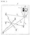
- a mobile terminal 7 is, for example, a PHS terminal that is carried by an employee that works at the building premises 10. Mobile terminal 7 has its physical location altered within the building by being carried by the employee.
- a private PHS network is installed in premises 10 that allows usage of mobile terminal 7 as an extension 2.
- PBX 3 is connected to a private repeater 5 (5A, 5B, 5C ... ) by communication lines 4A, 4B, 4C ... that are arranged indoor of the building of premises 10.
- PBX 3 functions as the control station that coordinates the communication through the extension of mobile terminal 7 via repeaters 5A, 5B, 5C ... .
- an ID transmitter 6 (6A, 6B, 6C ... ) transmitting an ID (identification information) representative thereof is provided independent of the private network including repeaters 5A, 5B, 5C ... .
- a center station 1 functions to identify the position of mobile terminal 7.
- a personal computer 1A used for locating is installed at center station 1.
- the position information corresponding to the position where ID transmitter 6 is installed is prestored in personal computer 1A on an ID-by-ID basis.
- Personal computer 1A is connected to PBX 3 through the extension.
- the received field intensity information output from mobile terminal 7 is applied to personal computer 1A via any of the plurality of repeaters 5A, 5B, 5C ... .
- Mobile terminal 7 identifies each repeater 5 by the repeater identification code transmitted from repeaters 5A, 5B, 5C ... , and constantly monitors the received field intensity of the wave output from each repeater 5.
- a repeater 5 is selected according to the level of the received field intensity to register the call area at PBX 3. By such a procedure, a link channel is established between mobile terminal 7 and control station 3. When there is a communication to or from mobile terminal 7, control is effected to connect the call. As a result, conversation or communication is allowed.
- Mobile terminal 7 selects an appropriate repeater 5 while measuring the received field intensity of each of ID transmitters 6A, 6B, 6C ... .
- Each detected received field intensity is stored internally classified by the ID issued from each of ID transmitters 6A, 6B, 6C ... .
- Mobile terminal 7 also measures the received electric field intensity of repeaters 5A, 5B, 5C ... , and stores internally the detected received field intensity classified by the identification code issued from each of repeaters 5A, 5B, 5C ... .
- the received field intensity of ID transmitter 6 and repeater 5 stored in mobile terminal 7 is altered in accordance with the shift, if any, of mobile terminal 7 within premises 10.
- the staff of center station 1 operates personal computer 1A to send a call to mobile terminal 7. Under control of PBX 3, connection is established between personal computer 1A and mobile terminal 7.
- the present embodiment may be implemented so that a call is automatically sent to mobile terminal 7 at a constant time interval without the operation of the staff of center station 1.
- Mobile terminal 7 transmits the received field intensity information of each of ID transmitters 6A, 6B, 6C ... and each of repeaters 5A, 5B, 5C ... stored internally in response to a request from personal computer 1A.
- the transmitted received field intensity information is input to personal computer 1A via repeater 5 located at the registered call area.
- Position information indicating the location of each of ID transmitters 6A, 6B, 6C ... is stored in personal computer 1A, classified by the ID of ID transmitter 6.
- the position information indicating the location of each of repeaters 5A, 5B, 5C ... is also stored in personal computer 1A, classified by the identification code of repeater 5.
- Personal computer 1A identifies the position of mobile terminal 7 from the input received field intensity information and the internally-stored position information. For example, personal computer 1A identifies the possible location range of mobile terminal 7 from the received field intensity of each of ID transmitters 6A, 6B, 6C ... and each of repeaters 5A, 5B, 5C ... , and then determines the position of mobile terminal 7 by computing the overlapping area of each identified range.
- the identified result of the location of mobile terminal 7 is displayed, for example, on a monitor screen connected to personal computer 1A.
- the position of mobile terminal 7 is indicated to the staff of center station I.
- ID transmitter 6 includes an ID memory unit 65 for storing a predetermined ID, a signal generation unit 64 generating an ID signal according to the ID stored in ID memory unit 65, a modulation unit 63 modulating the ID signal generated by signal generation unit 64, an output unit 62 for providing the ID signal modulated by modulation unit 63, and an antenna unit 61.
- ID transmitter 6 has the function to appropriately arrange the wave among repeaters 5 and among ID transmitters 6. This is required to establish synchronization with the timing of repeater 5. Control is provided so as to allocate the slot of the control channel with the timing of repeaters 5 deviated from each other in a self-isolating manner.
- Signal generation unit 64 continuously generates an ID signal. Therefore, an ID is continuously emitted from antenna unit 61 by a wave of a predetermined frequency and a predetermined transmission output corresponding to the private usage.
- ID transmitter 6 does not have the feature to receive information from mobile terminal 7 and the like. ID transmitter 6 only has the transmitting feature of sending the internally stored ID towards mobile terminal 7. Therefore, ID transmitter 6 can be made more compact and lighter than repeater 5 that is relatively small in size and weight (for example, capacity: 3-10 litters; weight: 3-10 kg). This means that the trouble of installing the facility is not required in this case where the position of mobile terminal 7 is to be identified taking advantage of the received electric field intensity of ID transmitter 6 than of repeater 5. Also, extra area to install the facility will not be required. Furthermore, a line connection unit to connect the wires of communication lines 4A, 4B, 4C ... as for repeater 5 is not required since ID transmitter 6 is absent of the feature of relaying information of mobile terminal 7 as repeater 5.
- ID transmitter 6 structured as described above, the cost of the facility and installation to improve the accuracy of the location can be suppressed by installing many more ID transmitters 6 than in the case of installing more repeaters 5. Furthermore, since the connection of ID transmitter 6 with PBX 3 is dispensable contrary to repeater 5, it is not necessary to increase the extension connection package of the PBX 3 end or replace PBX 3 itself with another type of higher line capacity. By employing ID transmitter 6 affirmatively for position identification, the accuracy of the location can be improved with the cost as low as possible.
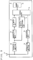
- Fig. 3 is a block diagram showing a structure of mobile terminal 7.
- Mobile terminal 7 includes an antenna unit 71, a reception amplifier 72, a demodulation unit 73, an ID detect unit 74, a control unit 75, a memory unit 76, a received field intensity measurement unit 77, a modulation unit 78, and a transmission amplifier 79.
- the wave issued from ID transmitter 6 is received by antenna unit 71.
- This wave is amplified by reception amplifier 72 and converted into an intermediate frequency to be output to demodulation 73 and received field intensity measurement unit 77.
- Received field intensity measurement unit 77 measures the received field intensity of each ID transmitter 6 according to the output of reception amplifier 72. The result of the measured received field intensity is output to control unit 75.
- Demodulation unit 73 demodulates the output signal of reception amplifier 72. The demodulated signal is applied to ID detect unit 74.
- ID detect unit 74 detects the ID of ID transmitter 6 from the demodulated signal. The detected result is supplied to control unit 75.
- Control unit 75 sequentially stores into memory unit 76 the ID output from ID detect unit 74 and the information of the received field intensity output from received field intensity measurement unit 77 as a pair of received field intensity information.
- the wave issued from each repeater 5 is received on antenna unit 71.
- the wave is amplified by reception amplifier 72 to be provided to demodulation unit 73 and received field intensity measurement unit 77.
- Received field intensity measurement unit 77 measures the received field intensity of each repeater 5 according to that output. The measured result is applied to control unit 75.
- Demodulation unit 73 demodulates the signal output from reception amplifier 72.
- the demodulated signal is applied to ID detect unit 74.
- ID detect unit 74 detects the identification code of repeater 5 according to the signal output from demodulation unit 73.
- the detected result is applied to control unit 75.
- Control unit 75 sequentially stores into memory unit 76 the identification code output from ID detect unit 74 and the received field intensity output from received field intensity measurement unit 77 as one pair of received field intensity information. Control unit 75 selects an appropriate repeater 5 to be used for communication according to the received field intensity information stored in memory unit 76. Then, control unit 75 provides to modulation unit 78 the signal to register the selected repeater 5 to PBX 3 (refer to Fig. 1). The signal provided to modulation unit 78 is modulated into a predetermined high frequency signal. Then, the signal is amplified by transmission amplifier 79 to be output from antenna unit 71.
- Communication between personal computer 1A and mobile terminal 7 is enabled by calling mobile terminal 7 from personal computer 1A (refer to Fig. 1) installed at a remote site.
- Control unit 75 responds to a transmission request of personal computer 1A to provide to modulation unit 78 the received field intensity information (the information pair of the ID and received field intensity of each ID transmitter 6, and the information pair of the identification code and received field intensity of each repeater 5) stored in memory unit 76.
- the received field intensity information is applied to the preselected repeater 5 via modulation unit 78, transmission amplifier 79, and antenna unit 71.
- the information applied to repeater 5 is input to personal computer 1A via PBX 3.
- the position of mobile terminal 7 is identified according to the input received field intensity information.
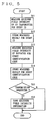
- Fig. 4 is a flow chart showing the process of ID transmitter 6. Under the condition of the power being turned on (S1), ID transmitter 6 issues the ID stored in ID memory unit 65 (S2). ID transmitter 6 carries out this process repeatedly. Thus, an ID is continuously emitted from ID transmitter 6.
- Fig. 5 is a flow chart showing the process of mobile terminal 7.
- Mobile terminal 7 executes the process set forth in the following repeatedly for every predetermined time.
- the control program required to execute the following process is stored in control unit 75.
- mobile terminal 7 measures the received field intensity of each ID transmitter 6 on an ID-by-ID basis (S11).
- the measured result of the received field intensity of each ID transmitter 6 is stored in memory unit 76, classified by the ID (S12).
- the received field intensity of each repeater 5 is measured on for every different identification code (S13).
- the measured result of the received field intensity of each repeater 5 is stored in memory 76, classified by the identification code (S14).
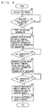
- Fig. 6 is a flow chart showing the process of personal computer 1A.
- the control program required to execute the process set forth in the following is stored in a ROM (Read Only Memory) not shown in personal computer 1A.
- Personal computer 1A is manipulated by the operator to request transmission of received field intensity information to mobile terminal 7 (S20). Determination is made whether received field intensity information is input from mobile terminal 7 (S21). Waiting is conducted until the received field intensity information is input.
- the position information of repeater 5 and the position information of ID transmitter 6 stored in personal computer 1A is called up (S22). Then, the range where mobile terminal 7 can be present is computed according to the received field intensity information of transmitter 6 among the input received field intensity information and the position information of transmitter 6 out of the retrieved position information (S23). This process is carried out for all the received field intensity information corresponding to ID transmitter 6. When the process of S23 ends for all the received field intensity information corresponding to ID transmitter 6, determination of YES is made at S24. Then, the range where mobile terminal 7 can be present is computed according to the position information of repeater 5 and the received field intensity information corresponding to repeater 5 (S25). This process is carried out for all the received field intensity information corresponding to repeater 5. When the process of S25 ends for all the received field intensity information corresponding to repeater 5, determination of YES is made at S26.
- the overlapping area of the computed result of S23 and computed result of S25 is obtained.
- the position of mobile terminal 7 is identified by this computed result (S27). More specifically, the overlapping area out from the computed range of mobile terminal 7 at S23 and S25 is identified as the location of mobile terminal 7.
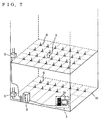
- Fig. 7 shows a structure of ID transmitter 6, mobile terminal 7, and repeater 4 provided in building premises 10.
- Premises 10 is, for example, a building of a plurality of stories.
- ID transmitter 6 is arranged on each floor in a lattice manner.
- the main body of ID transmitter 6 is embedded inside the floor so as to avoid being an obstacle in passage.
- a private repeater 5 for radio communication with mobile terminal 7 is installed at a predetermined site on each floor. Repeater 5 is connected through a private line to PBX 3 located at the basement of the building. Personal computer 1A of center station 1 is connected to the extension channel of PBX 3. Personal computer 1A is configured to identify the position of mobile terminal 7 that is moved throughout the building.
- the position of mobile terminal 7 during movement in a building of a plurality of stories can be supervised at one place in a centralized manner.
- This structure can be utilized in the case where, for example, the foreman of a working party in a construction work wants to acknowledge the location of each worker in a centralized manner by having each worker carry a mobile terminal (PHS terminal) 7 within the premises 10 of the construction work.
- the structure can be utilized in the case where mobile terminal (PHS terminal) 7 is attached to the luggage of a passenger at the premises of an airport to coordinate the luggage.
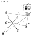
- Fig. 8 shows a structure of the entire system for describing another embodiment of the present invention.
- the present embodiment of Fig. 8 corresponds to the case where the public PHS network is applied.
- Mobile terminal 7 is located at a radio zone (simultaneous calling area) of any of repeater 50 (50A, 50B, 50C ... ) that constitutes the public PHS network.
- the person carrying mobile terminal 7 can communicate through voice and the like using the PHS.
- Repeater 50 is connected to a control station 30 that controls repeater 50 via a communication line 40 (40A, 40B, 40C ... ) of the ISDN.
- a central station 1 is provided remote from mobile terminal 7.
- Personal computer 1A of central station 1 is connected to control station 30 via a public line 20.
- Mobile terminal 7 measures the received field intensity of each of repeaters 50A, 50B, 50C ... and each of ID transmitters 60A, 60B, 60C ... .
- the measured intensity is stored internally, classified by the identification code of each repeater 50 and by the ID of each ID transmitter 60.
- connection between mobile terminal 7 and personal computer 1A is established by control station 30.
- mobile terminal 7 sends the received field intensity information of each repeater 50 and each ID transmitter 60 to the preselected repeater 50. Accordingly, the received field intensity information is applied to personal computer 1A via, for example, the communication channel.
- Personal computer 1A identifies the position of mobile terminal 7 according to the received field intensity information.
- the transmission of the received field intensity information employs the communication channel (traffic channel) in the present embodiment
- a control channel may be used instead. Accordingly, the communication cost can be reduced than the case where the traffic channel is used.
Landscapes
- Engineering & Computer Science (AREA)
- Computer Networks & Wireless Communication (AREA)
- Signal Processing (AREA)
- Physics & Mathematics (AREA)
- General Physics & Mathematics (AREA)
- Radar, Positioning & Navigation (AREA)
- Remote Sensing (AREA)
- Mobile Radio Communication Systems (AREA)
- Position Fixing By Use Of Radio Waves (AREA)
Applications Claiming Priority (2)
| Application Number | Priority Date | Filing Date | Title |
|---|---|---|---|
| JP554798 | 1998-01-14 | ||
| JP10005547A JPH11205845A (ja) | 1998-01-14 | 1998-01-14 | 位置特定システム |
Publications (2)
| Publication Number | Publication Date |
|---|---|
| EP0930514A2 true EP0930514A2 (fr) | 1999-07-21 |
| EP0930514A3 EP0930514A3 (fr) | 2000-09-27 |
Family
ID=11614226
Family Applications (1)
| Application Number | Title | Priority Date | Filing Date |
|---|---|---|---|
| EP98124879A Ceased EP0930514A3 (fr) | 1998-01-14 | 1998-12-30 | Système et procédé pour déterminer la position d'un terminal mobile |
Country Status (5)
| Country | Link |
|---|---|
| US (1) | US6415155B1 (fr) |
| EP (1) | EP0930514A3 (fr) |
| JP (1) | JPH11205845A (fr) |
| KR (1) | KR19990067886A (fr) |
| SG (1) | SG97776A1 (fr) |
Cited By (49)
| Publication number | Priority date | Publication date | Assignee | Title |
|---|---|---|---|---|
| WO2000050919A3 (fr) * | 1999-02-25 | 2000-12-07 | Microsoft Corp | Utilisation d'une table derivee de donnees concernant l'intensite de signal pour localiser et pister un utilisateur dans un reseau sans fil |
| WO2001031966A1 (fr) * | 1999-10-29 | 2001-05-03 | Cellpoint Systems Ab | Procede et dispositif relatifs a une localisation |
| EP1111951A3 (fr) * | 1999-12-21 | 2002-01-23 | Nortel Networks Limited | Systèmes d'accès sans fil et procédé pour localiser un appareil portable là-dedans |
| US6393294B1 (en) | 1998-09-22 | 2002-05-21 | Polaris Wireless, Inc. | Location determination using RF fingerprinting |
| FR2822610A1 (fr) * | 2001-03-26 | 2002-09-27 | Sagem | Procede de localisation de terminaux mobiles d'un reseau de radiotelephonie cellulaire |
| WO2002085057A1 (fr) * | 2001-04-06 | 2002-10-24 | Nokia Corporation | Systeme et procede de localisation |
| EP1303155A1 (fr) * | 2001-10-12 | 2003-04-16 | Ascom Tateco Ab | Système, méthode et dispositif de détermination de la position d'une station mobile dans un système de communication sans fil |
| DE10215725A1 (de) * | 2002-04-10 | 2003-11-13 | Koepenick Funkwerk Gmbh | Funk-Ortungssystem in digitalen Bündelfunknetzen |
| WO2004004399A1 (fr) * | 2002-06-28 | 2004-01-08 | Nokia Corporation | Support de service de localisation pour architecture de station emettrice-receptrice de base distribuee |
| WO2004014096A1 (fr) * | 2002-07-31 | 2004-02-12 | Koninklijke Philips Electronics N.V. | Systeme de localisation d'une unite mobile |
| WO2003058986A3 (fr) * | 2001-12-27 | 2004-05-13 | Qualcomm Inc | Creation et utilisation d'ephemerides d'une station de base dans un systeme de communications sans fil ayant une capacite de determination des positions |
| WO2004049632A1 (fr) * | 2002-11-27 | 2004-06-10 | Koninklijke Philips Electronics N.V. | Unite, systeme et procede de localisation |
| US6799047B1 (en) | 1999-02-25 | 2004-09-28 | Microsoft Corporation | Locating and tracking a user in a wireless network through environmentally profiled data |
| US6839560B1 (en) | 1999-02-25 | 2005-01-04 | Microsoft Corporation | Using a derived table of signal strength data to locate and track a user in a wireless network |
| WO2005031383A1 (fr) * | 2003-09-27 | 2005-04-07 | Koninklijke Philips Electronics N.V. | Reseau pour localiser une balise sans fil |
| WO2005032202A1 (fr) * | 2003-10-02 | 2005-04-07 | Telefonaktiebolaget Lm Ericsson (Publ) | Procede de determination de la position de stations mobiles |
| US6990428B1 (en) | 2003-07-28 | 2006-01-24 | Cisco Technology, Inc. | Radiolocation using path loss data |
| EP1359714A3 (fr) * | 2002-05-02 | 2006-06-21 | Microsoft Corporation | Méthode de détermination de la localisation d'un ordinateur mobile |
| WO2006090258A1 (fr) * | 2005-02-25 | 2006-08-31 | Nokia Corporation | Services de location dans un systeme de communications |
| US7116988B2 (en) | 2004-03-16 | 2006-10-03 | Airespace, Inc. | Location of wireless nodes using signal strength weighting metric |
| EP1316897A4 (fr) * | 2000-08-07 | 2007-03-28 | Sharp Kk | Dispositif serveur servant a traiter des informations selon des informations concernant la position d'un terminal |
| US7205938B2 (en) | 2004-03-05 | 2007-04-17 | Airespace, Inc. | Wireless node location mechanism responsive to observed propagation characteristics of wireless network infrastructure signals |
| US7260408B2 (en) | 2004-02-20 | 2007-08-21 | Airespace, Inc. | Wireless node location mechanism using antenna pattern diversity to enhance accuracy of location estimates |
| US7286835B1 (en) | 2004-09-10 | 2007-10-23 | Airespace, Inc. | Enhanced wireless node location using differential signal strength metric |
| US7286515B2 (en) | 2003-07-28 | 2007-10-23 | Cisco Technology, Inc. | Method, apparatus, and software product for detecting rogue access points in a wireless network |
| US7286833B2 (en) | 2004-02-27 | 2007-10-23 | Airespace, Inc. | Selective termination of wireless connections to refresh signal information in wireless node location infrastructure |
| US7293088B2 (en) | 2003-07-28 | 2007-11-06 | Cisco Technology, Inc. | Tag location, client location, and coverage hole location in a wireless network |
| US7336670B1 (en) | 2003-06-30 | 2008-02-26 | Airespace, Inc. | Discovery of rogue access point location in wireless network environments |
| WO2008022575A1 (fr) * | 2006-08-16 | 2008-02-28 | Huawei Technologies Co., Ltd. | Procédé et dispositif pour améliorer le positionnement d'équipement d'utilisateur |
| US7342906B1 (en) | 2003-04-04 | 2008-03-11 | Airespace, Inc. | Distributed wireless network security system |
| US7346338B1 (en) | 2003-04-04 | 2008-03-18 | Airespace, Inc. | Wireless network system including integrated rogue access point detection |
| CN100381007C (zh) * | 2002-06-21 | 2008-04-09 | 诺基亚公司 | 用于包括中继器的无线网络的信号路径检测 |
| US7370362B2 (en) | 2005-03-03 | 2008-05-06 | Cisco Technology, Inc. | Method and apparatus for locating rogue access point switch ports in a wireless network |
| US7433696B2 (en) | 2004-05-18 | 2008-10-07 | Cisco Systems, Inc. | Wireless node location mechanism featuring definition of search region to optimize location computation |
| US7489661B2 (en) | 2003-04-04 | 2009-02-10 | Cisco Systems, Inc. | Dynamic transmit power configuration system for wireless network environments |
| US7516174B1 (en) | 2004-11-02 | 2009-04-07 | Cisco Systems, Inc. | Wireless network security mechanism including reverse network address translation |
| US7539169B1 (en) | 2003-06-30 | 2009-05-26 | Cisco Systems, Inc. | Directed association mechanism in wireless network environments |
| US7596376B2 (en) | 2005-02-18 | 2009-09-29 | Cisco Technology, Inc. | Methods, apparatuses and systems facilitating client handoffs in wireless network systems |
| EP2192706A2 (fr) | 2006-09-15 | 2010-06-02 | Itron, Inc. | Évaluation environnementale par RF intégrée |
| US7805140B2 (en) | 2005-02-18 | 2010-09-28 | Cisco Technology, Inc. | Pre-emptive roaming mechanism allowing for enhanced QoS in wireless network environments |
| US7821986B2 (en) | 2006-05-31 | 2010-10-26 | Cisco Technology, Inc. | WLAN infrastructure provided directions and roaming |
| US8478228B2 (en) | 2008-10-20 | 2013-07-02 | Qualcomm Incorporated | Mobile receiver with location services capability |
| US8532567B2 (en) | 2003-07-21 | 2013-09-10 | Qualcomm Incorporated | Method and apparatus for creating and using a base station almanac for position determination |
| US8600297B2 (en) | 2009-07-28 | 2013-12-03 | Qualcomm Incorporated | Method and system for femto cell self-timing and self-locating |
| DE102012214190A1 (de) * | 2012-08-09 | 2014-02-13 | Siemens Convergence Creators Gmbh | Verfahren zur Positionsbestimmung eines bewegten Objektes in einer Innenraumumgebung |
| US9137771B2 (en) | 2004-04-02 | 2015-09-15 | Qualcomm Incorporated | Methods and apparatuses for beacon assisted position determination systems |
| US9756599B2 (en) | 2015-05-12 | 2017-09-05 | Qualcomm Incorporated | Positioning reference signal (PRS) generation for multiple transmit antenna systems |
| EP3299837A1 (fr) * | 2016-09-27 | 2018-03-28 | TP Vision Holding B.V. | Procédé de détection de proximité |
| US9986526B2 (en) | 2009-06-26 | 2018-05-29 | Qualcomm Incorporated | Positioning in the presence of passive distributed elements |
Families Citing this family (46)
| Publication number | Priority date | Publication date | Assignee | Title |
|---|---|---|---|---|
| US8982856B2 (en) | 1996-12-06 | 2015-03-17 | Ipco, Llc | Systems and methods for facilitating wireless network communication, satellite-based wireless network systems, and aircraft-based wireless network systems, and related methods |
| US7054271B2 (en) | 1996-12-06 | 2006-05-30 | Ipco, Llc | Wireless network system and method for providing same |
| JPH11328564A (ja) * | 1998-05-15 | 1999-11-30 | Nec Commun Syst Ltd | 位置表示機能付き構内交換システム |
| US6891838B1 (en) * | 1998-06-22 | 2005-05-10 | Statsignal Ipc, Llc | System and method for monitoring and controlling residential devices |
| US6437692B1 (en) | 1998-06-22 | 2002-08-20 | Statsignal Systems, Inc. | System and method for monitoring and controlling remote devices |
| US6914893B2 (en) | 1998-06-22 | 2005-07-05 | Statsignal Ipc, Llc | System and method for monitoring and controlling remote devices |
| US8410931B2 (en) | 1998-06-22 | 2013-04-02 | Sipco, Llc | Mobile inventory unit monitoring systems and methods |
| US7650425B2 (en) | 1999-03-18 | 2010-01-19 | Sipco, Llc | System and method for controlling communication between a host computer and communication devices associated with remote devices in an automated monitoring system |
| EP1056306B1 (fr) * | 1999-05-26 | 2006-10-11 | Sony Deutschland GmbH | Localisation geographique |
| JP2001255365A (ja) * | 2000-03-13 | 2001-09-21 | Matsushita Electric Ind Co Ltd | 移動局位置検出システム |
| US20010036832A1 (en) * | 2000-04-14 | 2001-11-01 | Onscene, Inc. | Emergency command and control system |
| GB0011643D0 (en) * | 2000-05-16 | 2000-07-05 | Hewlett Packard Co | Retrieval of location-related information |
| GB0012143D0 (en) | 2000-05-20 | 2000-07-12 | Hewlett Packard Co | Obtaining location updates about mobile entity for use in a location-sensitive application |
| GB0012445D0 (en) * | 2000-05-24 | 2000-07-12 | Hewlett Packard Co | Location-based equipment control |
| GB0012749D0 (en) * | 2000-05-26 | 2000-07-19 | Hewlett Packard Co | Finding locally-relevant information in a physical document |
| US6735444B2 (en) * | 2000-12-21 | 2004-05-11 | Telefonaktiebolaget Lm Ericsson (Publ) | Method and system for locating a device using a local wireless link |
| US7139580B2 (en) * | 2001-04-24 | 2006-11-21 | Qualcomm Incorporated | Method and apparatus for estimating the position of a terminal based on identification codes for transmission sources |
| US6873851B2 (en) * | 2001-05-03 | 2005-03-29 | International Business Machines Corporation | Method, system, and program for providing user location information for a personal information management system from transmitting devices |
| US6915135B1 (en) * | 2001-05-15 | 2005-07-05 | Praxis Technology Group, Inc. | Method and system for detecting object presence and its duration in a given area |
| JP2003114952A (ja) * | 2001-10-09 | 2003-04-18 | Nippon Telegr & Teleph Corp <Ntt> | 通信システム |
| US8489063B2 (en) | 2001-10-24 | 2013-07-16 | Sipco, Llc | Systems and methods for providing emergency messages to a mobile device |
| US7480501B2 (en) | 2001-10-24 | 2009-01-20 | Statsignal Ipc, Llc | System and method for transmitting an emergency message over an integrated wireless network |
| US7424527B2 (en) | 2001-10-30 | 2008-09-09 | Sipco, Llc | System and method for transmitting pollution information over an integrated wireless network |
| CN101222254A (zh) | 2001-11-20 | 2008-07-16 | 高通股份有限公司 | 受反向链路功率控制的中继器 |
| US7831263B2 (en) * | 2002-11-08 | 2010-11-09 | Qualcomm Incorporated | Apparatus and method for determining the location of a repeater |
| US7047020B2 (en) * | 2003-07-16 | 2006-05-16 | Qualcomm Inc. | Assistance techniques for subscriber units having positioning capabilities |
| US7212798B1 (en) | 2003-07-17 | 2007-05-01 | Cisco Technology, Inc. | Adaptive AGC in a wireless network receiver |
| KR100562228B1 (ko) * | 2004-02-23 | 2006-03-22 | 에스케이 텔레콤주식회사 | Cdma 이동 통신망에서의 특정 호출 채널을 이용한이동통신 단말기의 측위 방법 및 시스템 |
| US7756086B2 (en) | 2004-03-03 | 2010-07-13 | Sipco, Llc | Method for communicating in dual-modes |
| US8031650B2 (en) | 2004-03-03 | 2011-10-04 | Sipco, Llc | System and method for monitoring remote devices with a dual-mode wireless communication protocol |
| RU2355129C2 (ru) * | 2004-04-05 | 2009-05-10 | Квэлкомм Инкорпорейтед | Ретранслятор, который сообщает об обнаруженных соседях |
| CN1954232A (zh) * | 2004-04-05 | 2007-04-25 | 高通股份有限公司 | 具有定位能力的中继器 |
| US7778596B2 (en) | 2004-07-29 | 2010-08-17 | Qualcomm Incorporated | Airlink sensing watermarking repeater |
| US9439126B2 (en) | 2005-01-25 | 2016-09-06 | Sipco, Llc | Wireless network protocol system and methods |
| WO2008007129A1 (fr) * | 2006-07-14 | 2008-01-17 | Multitone Electronics Plc | Système et procédé de télécommunication |
| GB2449278B (en) * | 2007-05-16 | 2009-10-07 | Multitone Electronics Plc | Telecommunications system and method |
| US7616555B2 (en) * | 2006-10-03 | 2009-11-10 | Cisco Technology, Inc. | Minimum variance location estimation in wireless networks |
| US7835749B1 (en) | 2006-10-03 | 2010-11-16 | Cisco Technology, Inc. | Location inspector in wireless networks |
| US7626969B2 (en) * | 2006-10-04 | 2009-12-01 | Cisco Technology, Inc. | Relative location of a wireless node in a wireless network |
| US7983667B2 (en) | 2006-10-05 | 2011-07-19 | Cisco Technology, Inc. | Radio frequency coverage map generation in wireless networks |
| US7904092B2 (en) * | 2007-01-04 | 2011-03-08 | Cisco Technology, Inc. | Locally adjusted radio frequency coverage maps in wireless networks |
| KR101454021B1 (ko) * | 2007-08-07 | 2014-10-27 | 삼성전자주식회사 | 이동통신시스템에서 홈셀/개인네트워크셀의 메저먼트 장치및 방법 |
| JP4974378B2 (ja) | 2007-12-28 | 2012-07-11 | アズビル株式会社 | 固有情報設定システムおよび固有情報設定装置 |
| US8077031B2 (en) * | 2009-08-20 | 2011-12-13 | Consortium P, Inc. | Position locating by polyhedral morphing |
| KR101294864B1 (ko) * | 2011-10-17 | 2013-08-23 | (주)텔레필드 | 가시광 무선 통신 시스템에서의 광 송신기의 위치 변화 장치 및 방법 |
| JP7226319B2 (ja) * | 2017-08-08 | 2023-02-21 | 日本電産株式会社 | 移動体測位システムおよび物流管理システム |
Family Cites Families (12)
| Publication number | Priority date | Publication date | Assignee | Title |
|---|---|---|---|---|
| EP0556575B1 (fr) * | 1992-01-20 | 1998-09-30 | Nec Corporation | Système de localisation des personnes |
| JPH06213991A (ja) | 1993-01-14 | 1994-08-05 | Fujitsu Ltd | デッカ・ナビゲータ・システムにおけるゾーン・スリップの検出・較正方式 |
| FR2715013B1 (fr) * | 1994-01-12 | 1996-03-29 | Nortel Matra Cellular | Procédé de localisation d'une station mobile de radiocommunication cellulaire, et équipements pour la mise en Óoeuvre du procédé. |
| US5613205A (en) * | 1995-03-31 | 1997-03-18 | Telefonaktiebolaget Lm Ericsson | System and method of locating a mobile terminal within the service area of a cellular telecommunication system |
| US5724660A (en) * | 1995-06-07 | 1998-03-03 | At&T Wireless Services, Inc. | Method and apparatus for locating a mobile station by comparing calculated location area with GPS coordinates |
| JPH102950A (ja) * | 1995-07-25 | 1998-01-06 | Rookasu:Kk | 位置決めシステム |
| GB2304250A (en) * | 1995-08-12 | 1997-03-12 | Nat Vulcan Safety Products Ltd | Tracking a moveable object |
| JPH09171070A (ja) | 1995-12-20 | 1997-06-30 | Fujitsu General Ltd | 測位システム |
| JP3231787B2 (ja) * | 1996-03-05 | 2001-11-26 | 松下電器産業株式会社 | 位置情報検出システム |
| GB2311697B (en) * | 1996-03-22 | 1999-07-28 | Matsushita Electric Industrial Co Ltd | Wireless communication system and method and system for detection of position of radio mobile station |
| JPH1047982A (ja) * | 1996-08-06 | 1998-02-20 | Sony Corp | 位置測定装置、位置測定方法、ナビゲーション装置、ナビゲーション方法、情報サービス方法及び自動車 |
| US6055434A (en) * | 1997-02-11 | 2000-04-25 | Ericsson Inc. | Method and system for locating a mobile station within a mobile telecommunications network |
-
1998
- 1998-01-14 JP JP10005547A patent/JPH11205845A/ja not_active Withdrawn
- 1998-12-24 SG SG9805958A patent/SG97776A1/en unknown
- 1998-12-30 EP EP98124879A patent/EP0930514A3/fr not_active Ceased
-
1999
- 1999-01-05 US US09/225,544 patent/US6415155B1/en not_active Expired - Fee Related
- 1999-01-13 KR KR1019990000729A patent/KR19990067886A/ko not_active Abandoned
Cited By (74)
| Publication number | Priority date | Publication date | Assignee | Title |
|---|---|---|---|---|
| US6393294B1 (en) | 1998-09-22 | 2002-05-21 | Polaris Wireless, Inc. | Location determination using RF fingerprinting |
| US7725111B2 (en) | 1998-09-22 | 2010-05-25 | Polaris Wireless, Inc. | Location determination using RF fingerprinting |
| US8068855B2 (en) | 1998-09-22 | 2011-11-29 | Polaris Wireless, Inc. | Location determination using RF fingerprinting |
| US6799047B1 (en) | 1999-02-25 | 2004-09-28 | Microsoft Corporation | Locating and tracking a user in a wireless network through environmentally profiled data |
| WO2000050919A3 (fr) * | 1999-02-25 | 2000-12-07 | Microsoft Corp | Utilisation d'une table derivee de donnees concernant l'intensite de signal pour localiser et pister un utilisateur dans un reseau sans fil |
| US7020475B2 (en) | 1999-02-25 | 2006-03-28 | Microsoft Corporation | Using a derived table of signal strength data to locate and track a user in a wireless network |
| USRE45260E1 (en) | 1999-02-25 | 2014-11-25 | Microsoft Corporation | Using a derived table of signal strength data to locate and track a user in a wireless network |
| USRE46501E1 (en) | 1999-02-25 | 2017-08-01 | Microsoft Technology Licensing, Llc | Using a derived table of signal strength data to locate and track a user in a wireless network |
| US6839560B1 (en) | 1999-02-25 | 2005-01-04 | Microsoft Corporation | Using a derived table of signal strength data to locate and track a user in a wireless network |
| WO2001031966A1 (fr) * | 1999-10-29 | 2001-05-03 | Cellpoint Systems Ab | Procede et dispositif relatifs a une localisation |
| EP1111951A3 (fr) * | 1999-12-21 | 2002-01-23 | Nortel Networks Limited | Systèmes d'accès sans fil et procédé pour localiser un appareil portable là-dedans |
| EP1316897A4 (fr) * | 2000-08-07 | 2007-03-28 | Sharp Kk | Dispositif serveur servant a traiter des informations selon des informations concernant la position d'un terminal |
| FR2822610A1 (fr) * | 2001-03-26 | 2002-09-27 | Sagem | Procede de localisation de terminaux mobiles d'un reseau de radiotelephonie cellulaire |
| DE10212608B4 (de) * | 2001-03-26 | 2013-10-31 | Apple Inc. | Verfahren zur Lokalisierung von mobilen Endgeräten eines zellularen Funktelefonnetzes |
| WO2002085057A1 (fr) * | 2001-04-06 | 2002-10-24 | Nokia Corporation | Systeme et procede de localisation |
| EP1303155A1 (fr) * | 2001-10-12 | 2003-04-16 | Ascom Tateco Ab | Système, méthode et dispositif de détermination de la position d'une station mobile dans un système de communication sans fil |
| WO2003058986A3 (fr) * | 2001-12-27 | 2004-05-13 | Qualcomm Inc | Creation et utilisation d'ephemerides d'une station de base dans un systeme de communications sans fil ayant une capacite de determination des positions |
| DE10215725A1 (de) * | 2002-04-10 | 2003-11-13 | Koepenick Funkwerk Gmbh | Funk-Ortungssystem in digitalen Bündelfunknetzen |
| EP1359714A3 (fr) * | 2002-05-02 | 2006-06-21 | Microsoft Corporation | Méthode de détermination de la localisation d'un ordinateur mobile |
| CN1324505C (zh) * | 2002-05-02 | 2007-07-04 | 微软公司 | 确定移动计算机位置的方法和系统 |
| CN100381007C (zh) * | 2002-06-21 | 2008-04-09 | 诺基亚公司 | 用于包括中继器的无线网络的信号路径检测 |
| CN100423605C (zh) * | 2002-06-28 | 2008-10-01 | 诺基亚公司 | 用于分布式bts体系结构的通信系统 |
| WO2004004399A1 (fr) * | 2002-06-28 | 2004-01-08 | Nokia Corporation | Support de service de localisation pour architecture de station emettrice-receptrice de base distribuee |
| WO2004014096A1 (fr) * | 2002-07-31 | 2004-02-12 | Koninklijke Philips Electronics N.V. | Systeme de localisation d'une unite mobile |
| WO2004049632A1 (fr) * | 2002-11-27 | 2004-06-10 | Koninklijke Philips Electronics N.V. | Unite, systeme et procede de localisation |
| US7342906B1 (en) | 2003-04-04 | 2008-03-11 | Airespace, Inc. | Distributed wireless network security system |
| US7489661B2 (en) | 2003-04-04 | 2009-02-10 | Cisco Systems, Inc. | Dynamic transmit power configuration system for wireless network environments |
| US7346338B1 (en) | 2003-04-04 | 2008-03-18 | Airespace, Inc. | Wireless network system including integrated rogue access point detection |
| US7453840B1 (en) | 2003-06-30 | 2008-11-18 | Cisco Systems, Inc. | Containment of rogue systems in wireless network environments |
| US7539169B1 (en) | 2003-06-30 | 2009-05-26 | Cisco Systems, Inc. | Directed association mechanism in wireless network environments |
| US7336670B1 (en) | 2003-06-30 | 2008-02-26 | Airespace, Inc. | Discovery of rogue access point location in wireless network environments |
| US8000308B2 (en) | 2003-06-30 | 2011-08-16 | Cisco Technology, Inc. | Containment of rogue systems in wireless network environments |
| US8089974B2 (en) | 2003-06-30 | 2012-01-03 | Cisco Systems, Inc. | Discovery of rogue access point location in wireless network environments |
| US8532567B2 (en) | 2003-07-21 | 2013-09-10 | Qualcomm Incorporated | Method and apparatus for creating and using a base station almanac for position determination |
| US8077079B2 (en) | 2003-07-28 | 2011-12-13 | Cisco Technology, Inc. | Radiolocation using path loss data |
| US6990428B1 (en) | 2003-07-28 | 2006-01-24 | Cisco Technology, Inc. | Radiolocation using path loss data |
| US8264402B2 (en) | 2003-07-28 | 2012-09-11 | Cisco Technology, Inc. | Radiolocation using path loss data |
| US7286515B2 (en) | 2003-07-28 | 2007-10-23 | Cisco Technology, Inc. | Method, apparatus, and software product for detecting rogue access points in a wireless network |
| US7916705B2 (en) | 2003-07-28 | 2011-03-29 | Cisco Technology, Inc. | Method, apparatus, and software product for detecting rogue access points in a wireless network |
| US7293088B2 (en) | 2003-07-28 | 2007-11-06 | Cisco Technology, Inc. | Tag location, client location, and coverage hole location in a wireless network |
| US7558852B2 (en) | 2003-07-28 | 2009-07-07 | Cisco Technology, Inc. | Tag location, client location, and coverage hole location in a wireless network |
| WO2005031383A1 (fr) * | 2003-09-27 | 2005-04-07 | Koninklijke Philips Electronics N.V. | Reseau pour localiser une balise sans fil |
| WO2005032202A1 (fr) * | 2003-10-02 | 2005-04-07 | Telefonaktiebolaget Lm Ericsson (Publ) | Procede de determination de la position de stations mobiles |
| US7532896B2 (en) | 2004-02-20 | 2009-05-12 | Cisco Systems, Inc. | Wireless node location mechanism using antenna pattern diversity to enhance accuracy of location estimates |
| US7260408B2 (en) | 2004-02-20 | 2007-08-21 | Airespace, Inc. | Wireless node location mechanism using antenna pattern diversity to enhance accuracy of location estimates |
| US7286833B2 (en) | 2004-02-27 | 2007-10-23 | Airespace, Inc. | Selective termination of wireless connections to refresh signal information in wireless node location infrastructure |
| US7205938B2 (en) | 2004-03-05 | 2007-04-17 | Airespace, Inc. | Wireless node location mechanism responsive to observed propagation characteristics of wireless network infrastructure signals |
| US7116988B2 (en) | 2004-03-16 | 2006-10-03 | Airespace, Inc. | Location of wireless nodes using signal strength weighting metric |
| US9137771B2 (en) | 2004-04-02 | 2015-09-15 | Qualcomm Incorporated | Methods and apparatuses for beacon assisted position determination systems |
| US7433696B2 (en) | 2004-05-18 | 2008-10-07 | Cisco Systems, Inc. | Wireless node location mechanism featuring definition of search region to optimize location computation |
| US8204512B2 (en) | 2004-05-18 | 2012-06-19 | Cisco Technology | Wireless node location mechanism featuring definition of search region to optimize location computation |
| US7286835B1 (en) | 2004-09-10 | 2007-10-23 | Airespace, Inc. | Enhanced wireless node location using differential signal strength metric |
| US8200242B2 (en) | 2004-09-10 | 2012-06-12 | Cisco Technology, Inc. | Enhanced wireless node location using differential signal strength metric |
| US7966021B2 (en) | 2004-09-10 | 2011-06-21 | Cisco Systems, Inc. | Enhanced wireless node location using differential signal strength metric |
| US7941548B2 (en) | 2004-11-02 | 2011-05-10 | Cisco Systems, Inc. | Wireless network security mechanism including reverse network address translation |
| US7516174B1 (en) | 2004-11-02 | 2009-04-07 | Cisco Systems, Inc. | Wireless network security mechanism including reverse network address translation |
| US7805140B2 (en) | 2005-02-18 | 2010-09-28 | Cisco Technology, Inc. | Pre-emptive roaming mechanism allowing for enhanced QoS in wireless network environments |
| US7596376B2 (en) | 2005-02-18 | 2009-09-29 | Cisco Technology, Inc. | Methods, apparatuses and systems facilitating client handoffs in wireless network systems |
| US7917146B2 (en) | 2005-02-18 | 2011-03-29 | Cisco Technology, Inc. | Methods, apparatuses and systems facilitating client handoffs in wireless network systems |
| US8798018B2 (en) | 2005-02-18 | 2014-08-05 | Cisco Technology, Inc. | Pre-emptive roaming mechanism allowing for enhanced QoS in wireless network environments |
| WO2006090258A1 (fr) * | 2005-02-25 | 2006-08-31 | Nokia Corporation | Services de location dans un systeme de communications |
| US7370362B2 (en) | 2005-03-03 | 2008-05-06 | Cisco Technology, Inc. | Method and apparatus for locating rogue access point switch ports in a wireless network |
| US7821986B2 (en) | 2006-05-31 | 2010-10-26 | Cisco Technology, Inc. | WLAN infrastructure provided directions and roaming |
| WO2008022575A1 (fr) * | 2006-08-16 | 2008-02-28 | Huawei Technologies Co., Ltd. | Procédé et dispositif pour améliorer le positionnement d'équipement d'utilisateur |
| EP2192706A3 (fr) * | 2006-09-15 | 2011-04-27 | Itron, Inc. | Évaluation environnementale par RF intégrée |
| US8270910B2 (en) | 2006-09-15 | 2012-09-18 | Itron, Inc. | Embedded RF environmental evaluation tool to gauge RF transceivers performance need |
| EP2192706A2 (fr) | 2006-09-15 | 2010-06-02 | Itron, Inc. | Évaluation environnementale par RF intégrée |
| US8478228B2 (en) | 2008-10-20 | 2013-07-02 | Qualcomm Incorporated | Mobile receiver with location services capability |
| US9986526B2 (en) | 2009-06-26 | 2018-05-29 | Qualcomm Incorporated | Positioning in the presence of passive distributed elements |
| US8600297B2 (en) | 2009-07-28 | 2013-12-03 | Qualcomm Incorporated | Method and system for femto cell self-timing and self-locating |
| DE102012214190A1 (de) * | 2012-08-09 | 2014-02-13 | Siemens Convergence Creators Gmbh | Verfahren zur Positionsbestimmung eines bewegten Objektes in einer Innenraumumgebung |
| US9756599B2 (en) | 2015-05-12 | 2017-09-05 | Qualcomm Incorporated | Positioning reference signal (PRS) generation for multiple transmit antenna systems |
| US10051593B2 (en) | 2015-05-12 | 2018-08-14 | Qualcomm Incorporated | Positioning reference signal (PRS) generation for multiple transmit antenna systems |
| EP3299837A1 (fr) * | 2016-09-27 | 2018-03-28 | TP Vision Holding B.V. | Procédé de détection de proximité |
Also Published As
| Publication number | Publication date |
|---|---|
| EP0930514A3 (fr) | 2000-09-27 |
| JPH11205845A (ja) | 1999-07-30 |
| US6415155B1 (en) | 2002-07-02 |
| KR19990067886A (ko) | 1999-08-25 |
| SG97776A1 (en) | 2003-08-20 |
Similar Documents
| Publication | Publication Date | Title |
|---|---|---|
| US6415155B1 (en) | Location system and method for identifying position of mobile terminal that can communicate based on repeater in radio zone, and mobile terminal that can communicate based on repeater in radio zone | |
| US6745036B1 (en) | Location beacon system | |
| AU652041B2 (en) | Mobile radio communications system | |
| IT8322506A1 (it) | Impianto di localizzazione elettronico per persone riceventi chiamate telefoniche | |
| EP1018457A1 (fr) | Systeme de positionnement et dispositif de communication mobile | |
| GB2280327A (en) | Locating portable telephone | |
| US20030083008A1 (en) | Method and system for identifying repeater traffic in a code divsion multiple access system | |
| US6512924B2 (en) | Mobile communications system | |
| US6078821A (en) | Cordless radiotelephone system having an extendable geographic coverage area and method therefor | |
| KR19980031026A (ko) | Gps와 무선통신을 이용한 위치추적 시스템 | |
| CN1933670B (zh) | 接入点信息更新方法及使用其的越区切换支持设备和方法 | |
| JP3012606B1 (ja) | 基地局装置、移動局装置及びこれらを用いた移動通信システム、並びに移動通信方法 | |
| JPH10210536A (ja) | 無線移動端末 | |
| JPH09247737A (ja) | 位置情報検出システム | |
| JP3196634B2 (ja) | 無線移動端末 | |
| JP3543205B2 (ja) | 位置検出システム | |
| JPS6320071B2 (fr) | ||
| JPH08223105A (ja) | 無線電話システム | |
| JPH10108244A (ja) | 無線基地局保守システム | |
| JP2973806B2 (ja) | コードレス電話試験システム | |
| JPH1042344A (ja) | マイクロセル移動通信の携帯端末位置検出方法 | |
| EP0930591A1 (fr) | Localisation automatique d'individus utilisant une combinaison de média sans fil | |
| EP0917379A1 (fr) | Systeme et terminal de radiocommunications mobiles | |
| KR930015923A (ko) | 무선전화기에서의 동작상태 모니터 방법 | |
| JPH01223835A (ja) | コードレス電話装置 |
Legal Events
| Date | Code | Title | Description |
|---|---|---|---|
| PUAI | Public reference made under article 153(3) epc to a published international application that has entered the european phase |
Free format text: ORIGINAL CODE: 0009012 |
|
| AK | Designated contracting states |
Kind code of ref document: A2 Designated state(s): DE FI FR GB IT SE |
|
| AX | Request for extension of the european patent |
Free format text: AL;LT;LV;MK;RO;SI |
|
| PUAL | Search report despatched |
Free format text: ORIGINAL CODE: 0009013 |
|
| AK | Designated contracting states |
Kind code of ref document: A3 Designated state(s): AT BE CH CY DE DK ES FI FR GB GR IE IT LI LU MC NL PT SE |
|
| AX | Request for extension of the european patent |
Free format text: AL;LT;LV;MK;RO;SI |
|
| 17P | Request for examination filed |
Effective date: 20010307 |
|
| AKX | Designation fees paid |
Free format text: DE FI FR GB IT SE |
|
| GRAG | Despatch of communication of intention to grant |
Free format text: ORIGINAL CODE: EPIDOS AGRA |
|
| 17Q | First examination report despatched |
Effective date: 20011107 |
|
| STAA | Information on the status of an ep patent application or granted ep patent |
Free format text: STATUS: THE APPLICATION HAS BEEN REFUSED |
|
| 18R | Application refused |
Effective date: 20020429 |