EP0930687A2 - Presse-étoupe pour câble - Google Patents
Presse-étoupe pour câble Download PDFInfo
- Publication number
- EP0930687A2 EP0930687A2 EP99100268A EP99100268A EP0930687A2 EP 0930687 A2 EP0930687 A2 EP 0930687A2 EP 99100268 A EP99100268 A EP 99100268A EP 99100268 A EP99100268 A EP 99100268A EP 0930687 A2 EP0930687 A2 EP 0930687A2
- Authority
- EP
- European Patent Office
- Prior art keywords
- cable
- cable gland
- contact
- pressure
- gland according
- Prior art date
- Legal status (The legal status is an assumption and is not a legal conclusion. Google has not performed a legal analysis and makes no representation as to the accuracy of the status listed.)
- Granted
Links
Images


Classifications
-
- H—ELECTRICITY
- H02—GENERATION; CONVERSION OR DISTRIBUTION OF ELECTRIC POWER
- H02G—INSTALLATION OF ELECTRIC CABLES OR LINES, OR OF COMBINED OPTICAL AND ELECTRIC CABLES OR LINES
- H02G15/00—Cable fittings
- H02G15/02—Cable terminations
- H02G15/04—Cable-end sealings
-
- H—ELECTRICITY
- H02—GENERATION; CONVERSION OR DISTRIBUTION OF ELECTRIC POWER
- H02G—INSTALLATION OF ELECTRIC CABLES OR LINES, OR OF COMBINED OPTICAL AND ELECTRIC CABLES OR LINES
- H02G3/00—Installations of electric cables or lines or protective tubing therefor in or on buildings, equivalent structures or vehicles
- H02G3/02—Details
- H02G3/06—Joints for connecting lengths of protective tubing or channels, to each other or to casings, e.g. to distribution boxes; Ensuring electrical continuity in the joint
- H02G3/0616—Joints for connecting tubing to casing
- H02G3/0625—Joints for connecting tubing to casing with means for preventing disengagement of conductors
- H02G3/0666—Joints for connecting tubing to casing with means for preventing disengagement of conductors with means clamping the armour of the conductor
-
- H—ELECTRICITY
- H02—GENERATION; CONVERSION OR DISTRIBUTION OF ELECTRIC POWER
- H02G—INSTALLATION OF ELECTRIC CABLES OR LINES, OR OF COMBINED OPTICAL AND ELECTRIC CABLES OR LINES
- H02G3/00—Installations of electric cables or lines or protective tubing therefor in or on buildings, equivalent structures or vehicles
- H02G3/02—Details
- H02G3/06—Joints for connecting lengths of protective tubing or channels, to each other or to casings, e.g. to distribution boxes; Ensuring electrical continuity in the joint
- H02G3/0616—Joints for connecting tubing to casing
- H02G3/0691—Fixing tubing to casing by auxiliary means co-operating with indentations of the tubing, e.g. with tubing-convolutions
Definitions
- the invention relates to a cable gland comprising one with a defined electrical potential lying component, in particular a housing, connectable Nozzle, one that can be inserted into an interior of the nozzle Seal and a pressure element that can be screwed to the socket, which on the seal in the sense of an application the same to a jacket through the cable gland passed cable acts.
- Such cable glands are from the prior art known. With these cable glands, the cable should be tight completed with the component into which the nozzle can be screwed is to be connected.
- the object of the invention is therefore a cable gland and to create a cable assembly that one optimal and as protected as possible installation of a cable enables.
- This task is done with a cable gland at the beginning described type according to the invention solved in that a side of the pressure element opposite the neck a receptacle is provided in which one end of the Sheath of the cable surrounding and electrical over its length conductive cable protection hose can be used, that a connectable to the pressure element clamping element is provided with which the end of the cable protection conduit connectable mechanically and electrically to the pressure element is and that the pressure element with the nozzle and the Stubs are electrically connected to the component.
- the cable protection hose has a mechanical Protection for the cable provides and also the cable protection hose additionally an electrical shield for the Cable represents, by the electrical connection of the Cable protection hose ultimately with the component an excellent and in particular complete shielding of the cable is also guaranteed in the area of the cable gland.
- the seal between the cable and the nozzle advantageous to the extent that even in the Cable protection hose penetrating dirt or water this cannot get into the component, especially the housing and vice versa also no contamination from the housing in the Cable protection hose can enter.
- the solution according to the invention still has the great advantage that it is easy to install because of the cable protection hose for example then via the cable is feasible if this is connected with one end and already in the nozzle by means of the pressure element and Seal is fixed.
- a particularly cheap solution of the cable gland according to the invention stipulates that the recording as a recording for an end grommet of the cable protection conduit is formed.
- the Providing an end grommet for the cable protection conduit creates the Possibility of this mechanically stable on the one hand and on the other hand with good electrical contact on the pressure element fix.
- the end spout also has the great advantage that this sits firmly on the cable protection conduit and thus especially pre-assembled with the cable protection hose can be delivered.
- the receptacle is designed so that it one in the radial direction to a longitudinal axis of the cable gland extending contact surface for a contact element has the end spout.
- a particularly favorable design of the contact surface provides doing so that the contact surface is in the direction of an insertion opening the taper expanded.
- Such Contact surface has the advantage that it can be used even with different Tolerances in a simple way a safe and reliable Fixation of the contact element on the holder possible is.
- a particularly secure fixation of the contact element on the Contact surface is particularly possible if the contact element a also conical and the contact surface facing surface.
- the cone angle of the contact surface and the cone angle of the surface can be identical.
- cone angle between the two are different to approximate one to achieve linear contact between the two.
- a particularly favorable solution provides that the cone angle the surface of the contact element is smaller than the cone angle the contact surface, advantageously this Cone angle is made slightly smaller than that of the Contact surface.
- a particularly favorable solution provides that the contact element through one with its ring faces parallel to one Conical ring formed on the end grommet is formed.
- the electrically conductive connection can be very different Way come about.
- the end grommet be provided with contact springs which one is close to the admission and one is sufficient Provide good contact between the end grommet and the pressure element.
- a particularly favorable solution provides that the electrical Connection between the end grommet and the pressure element via an essentially linear arrangement of the two against each other he follows.
- the provision of a linear system for Making the connection between the two has the advantage that with it the highest possible surface pressure and thus the best possible electrical contact between them both can be achieved with the lowest possible contact resistance is.
- a particularly cheap solution provides that the end grommet an edge of the receptacle can be put on because it is particularly simple is for the essentially linear system between the two required edge in the receptacle to mold or mold to this while providing an edge in the area of the end grommet itself with more effort connected is.
- clamping element is a union nut comprises which can be screwed onto the pressure element, with such a cap nut, in the same way as with the pressure element, on the one hand large forces for fixing and The cable protection hose and the end grommet can be clamped are and on the other hand simple assembly is possible.
- the clamping element for example, from the union nut acted upon pressure part, which on the Contact element of the end grommet works.
- a pressure part particularly safe and permanent loading of the contact element guaranteed in the direction of the contact surface, since the Pressure ring over the entire extent of the contact element in Azimuth direction acts on the contact element.
- the Pressure part is designed to be elastic, so that this is for example can be biased by the union nut to constantly pressurized the end grommet on the pressure element Keep plant.
- a particularly secure fixation of the end grommet with the contact element is possible if the pressure part with a pressure wedge between an outside of the cable protection conduit and engages the contact element of the end grommet and thus an im essentially centered fixing of the cable protection conduit with the end grommet on the cable gland according to the invention guaranteed.
- a Shield contact element is arranged, which in electrical There is contact with the nozzle and by means of at least one in Direction of the contact bracket reaching through the cable an inner conductor area of the cable, exposed cable shield contacted.
- a particularly favorable solution provides that the contact bracket, preferably in an approximately parallel to the longitudinal axis the level of the cable gland, resiliently movable is, with this resilient movement a safe The cable shield can be contacted through the cable bracket is.
- Shield contact element has several contact brackets.
- the shield contact element Has carrier part on which the contact bracket is held are.
- the shield contact element can then be particularly inexpensive fix the socket if the shield contact element in a Recording the nozzle sits and thus in a simple manner and Way can be held securely on the neck.
- the carrier part is relative is arranged fixed to the neck and thus essentially is attached to the nozzle.
- the carrier part also an outer surface in the direction of the longitudinal axis of the cable gland is recorded.
- Shield contact element by means of at least one in a recess the claw engaging in the direction of the Longitudinal axis is fixed.
- the shield contact element advantageously provided that the shield contact element from a side of the pressure element opposite the Nozzle can be inserted into the receptacle.
- This page is usually the housing side of the nozzle.
- the receptacle connects to one of the Pressure element opposite opening of the nozzle, so that the shield contact element as close as possible to the component sits, in which the nozzle can be screwed.
- the invention relates not only to a cable gland, but also a cable assembly comprising one Cable gland and a cable held in this, wherein according to the invention the cable arrangement with a cable protection hose is provided and also according to the above described embodiments is formed.
- the advantage of this solution is already in the above discussed possibility of an advantageous shielding of the Cable.
- the cable protection hose variable in its longitudinal direction that is either is elastically stretchable or compressible, since it is an assembly of the cable protection conduit itself with both ends in the Cable glands fixed cable is possible.
- the cable protection hose one that is only electrically conductive in one spiral direction Element comprises such an electrically conductive Element, especially with variable length is easy and inexpensive to manufacture and especially in Connection to a cable shield provided in the cable anyway a sufficient additional shielding effect develops.
- Cable gland is preferably provided that the cable protection hose is provided with an end grommet.
- This end grommet can be designed in a wide variety of ways be.
- An advantageous solution provides that the End sleeve has an inner jacket for the cable protection conduit and thus with this inside the cable protection conduit on this.
- the end sleeve with the inner jacket on the Cable protection hose fixed. It would be conceivable that To glue the end grommet with the cable protection hose solder or connect using form-fitting elements. A particularly favorable positive connection provides that the end grommet engaging in the beads of the cable protection conduit own beads can be fixed on this.
- the end grommet has an outer jacket for the cable protection conduit.
- Cable gland is preferably provided that the end grommet extends from the cable protection hose to the outside extending contact element, which then to the Contact surface of the recording can be created.
- An expedient embodiment of such a receiving element stipulates that this is parallel to a conical surface extending ring is formed.
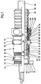
- a first embodiment of a cable gland according to the invention shown in Fig. 1 includes one as a whole designated by 10 and electrically conductive Stub, which has a cylindrical extension 12 with a Has external thread 14, which in a on a defined electrical component 16, preferably a wall of a housing can be screwed in.
- the nozzle 10 further includes a key surface section 18, which is provided with key surfaces 20 and on one a housing end 22 of the cylindrical Approach 12 opposite side immediately afterwards is arranged on the cylindrical neck 12 on the nozzle 10.
- Section 24 is used to hold a whole with 32 designated seal carrier, which with a retaining projection 34 engages in section 24 and on an inner Cylinder surface 36 of the same in the direction of a longitudinal axis 42 is led.
- the seal carrier 32 is also supported a flange surface 38 on one of the key surface section 18 facing away from flange surface 40 of the cylinder section 24 and is thereby in the direction of the longitudinal axis 42 of the cable gland against displacement in the direction of the flats section 18 secured.
- the seal carrier 32 further comprises a lamella basket 44, which in turn encloses a ring-shaped seal 46, the seal 46 further by an inner Approach 48 of the seal carrier 32 against displacement in Direction of the longitudinal axis 42 to the key surface section 18 is fixable.
- the lamellar basket 44 is in turn by a radially sloping surface 50 of the inside extending towards the longitudinal axis 42 Pressure nut 28 acted upon, which with increasing screwing the pressure nut 28 on the external thread 26 Slats of the slat basket 44 increasingly in the direction of Longitudinal axis 42 is deformed and thus that in the lamella basket 44 received seal 46 also so far in the direction of Longitudinal axis 42 moves that an inner passage 52 of the Seal 46 on a cable outer surface 54 of a cable 56 sealing with pressure can be applied to one hand Seal between the cable gland and the cable 56 and on the other hand a fixation of the cable 56 in the direction of Obtain longitudinal axis 42.
- the cable 56 runs through one to the longitudinal axis 52 coaxial opening of the pressure nut 26, then through the passage 52 of the seal 46 and then passes through an interior Breakthrough 60 of the seal carrier 32. Following the Seal carrier 32 extends the cable 56 through a Interior 62 of the nozzle 10, which is based on the Cylinder section 24 through the key surface section 18 and the cylindrical extension 12 to a housing side Opening 64 of the neck expands.
- the pressure nut 28 preferably has a cylindrical one Section 66, which carries the internal thread 30 and a adjoining key surface section 68, the has individual key surfaces 70 and approximately in the area the opening 58 of the pressure nut 28.
- the key surface portion 60 On one opposite the cylindrical section 66 The key surface portion 60 carries the pressure nut 28 a cylindrical one designated as a whole by 72 Section which is provided with an external thread 74.
- the cylindrical section 72 encloses an as Whole with 76 recording, which is based on an end opening 78 of the cylindrical section 72, the one on the key section 68 opposite Side of the cylindrical portion 72 is in the direction of Spanner flat section 68, inside the pressure nut 28 extends, up to a funnel-shaped on the Opening 58 tapering and insertion of the cable 56 lightening wall area 80.
- the receptacle 76 has one starting from the wall area 80 towards the end opening 78 extending and coaxial to the longitudinal axis 42 cylindrical wall surface 82 on which forming an edge 86, a contact surface 84 connects that from the edge 86 to the end opening 78 extends and extends from the radius of the cylindrical Wall surface 82 conical up to the end opening 78 expanded, preferably corresponding to one to the longitudinal axis 42 coaxial tapered surface.
- the end opening 78 provides an insertion opening for one end 90 of a cable protection hose 92, which for example as longitudinally elastic or longitudinally compressible Corrugated hose 98 made of thin metal and with in its longitudinal direction 94 with successive beads 96 is provided.
- a cable protection hose 92 which for example as longitudinally elastic or longitudinally compressible Corrugated hose 98 made of thin metal and with in its longitudinal direction 94 with successive beads 96 is provided.
- the end 90 of the cable protection hose 92 is with a provided with 100 designated end grommet, which with a Inner jacket 102 in the area of the end 90 in the cable protection hose 92 engages and has jacket beads 106, the in turn engage in the beads 96 of the corrugated hose 98 and thus fix the inner jacket 102 of the end grommet 100.
- an outer casing 112 of the end sleeve leading bend 108 formed, which an end edge 110 of the end 90 of the cable protection tube 92 encloses.
- the outer jacket 112 lies on an outside 114 of the cable protection hose 92 in the area of the end 90 and extends to a preferably ring-shaped Contact element 116, which is conical to the outer jacket 112 and extends radially outward from the cable protection tube 92.
- the contact element 116 preferably forms one Conical ring around the outer shell 112, which starting from the outer jacket 112 and in the direction of the bend 108 is flared away.
- the contact element 116 is shaped so that it protrudes far beyond the outer casing 112 in the radial direction, that this can be applied to the contact surface 84, in particular in the area of one of the edges 86 with which the Contact surface 84 merges into the cylindrical wall surface 82.
- the end grommet 100 is electrically conductive with the corrugated hose 98 connected, which also in its longitudinal direction 94 is electrically conductive over its entire length.
- the end grommet 100 By designing the end grommet 100 from electrically conductive Material or material with an electrically conductive Surface finishing, for example galvanizing thus also an electrical connection between the end grommet 100 and the pressure nut 28 with the cylindrical portion 72, in particular the bearing surface 84 of the same, preferably by pressing the contact element 116 to the contact surface 84, preferably in the region of the edge 86 due to an at least partially linear contact of the contact element 116 in the region of the edge 118 which for one good electrical contact required high surface pressure is achievable.
- Clamping element which has a union nut 122 having an internal thread 124 on the external thread 74 of the cylindrical projection 72 can be screwed on.
- the cap nut also has a radial over the internal thread 124 up to a passage opening 125 for the cable 56 internally drawn end flange 126, with which a preferably annular pressure piece 128 can be acted upon between the end flange 126 and the contact element 116 is arranged.
- the pressure element 128 in turn has an inner opening 130, which is penetrated by the cable protection tube 92 and surrounds it on its outside 114, and also an outer surface 132 that tapers in Direction towards an end acting on the contact element 116 134 runs, the cone angle is selected so that the End 134 between the contact element 116 of the end grommet 100 and engages the outside 114 of the cable protection hose 92 and thus on the one hand the entire unit consisting of end spout 100 and End 90 of the cable protection hose 92 in the direction of Key surface section 68 acted upon and the other at the same time the contact element 116 against the contact surface 84 and especially the edge 86 presses to the good electrical To make contact between this and the pressure nut 28, the pressure nut 28 in the simplest case is made of electrically conductive material.
- the pressure element 128 is preferably made of elastic Material formed so that the union nut 120 so far can be screwed onto the pressure nut 128 until the Pressure element 128 due to the elastic material Desired contact pressure for fixing the end 90 of the Cable protection hose 92 generated with the end grommet 100.
- the electrical Conductively trained and electrically conductive with the Stub 10 connected pressure nut 28, the end grommet that the Pressure nut 28 and the corrugated hose 98 electrically conductive connects with each other, as well as that over its entire Extension in the longitudinal direction 94 of electrically conductive corrugated hose 98 is a comprehensive electrical shield of the Cable 56 created in a cable arrangement according to the invention, including the cable gland, the cable 56 and the cable protection hose.
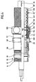
- an inventive Cable arrangement comprising a cable gland with a Cable and a cable protection hose, shown in Fig. 4, is in contrast to the first embodiment of the cable protection hose 92 not formed from a corrugated hose 98 ', which over the entire longitudinal extent 94 is electrically conductive, but for example from one Hose made of non-conductive electrical material or a Hose made of non-electrically connected Segments.
- the cable protection hose includes 92 'on an outer side 138 of the corrugated hose 98' additionally arranged metal mesh 140, which over the total extension of the cable protection hose 92 'in the Longitudinal direction 94 extends and also through the end grommet 100 between the outer jacket 112 and the outer side 138 of the Corrugated hose 98 'pinched and thus electrically through the end spout 100 is contacted, so that in turn electrical contact between the metal mesh 140 and the End grommet 100 and thus also the contact element 116 thereof exists and the contact is made in the same way can, the cable gland is identical as in the first embodiment.
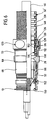
- FIG. 5 shown in FIG. 5 are the parts that match those of the first and the second embodiment are identical to the same Provide reference numerals so that with regard to their Description on the explanations to the previous Embodiments can be referenced.
- this shield contact element 152 has a carrier part 154, of which Contact springs 156 radially in the direction of the longitudinal axis 42 protrude and have an end bend 158, with which contact a screen 160 of the cable 56, which is covered by an outer jacket 162 in the cable 56 and encloses an inner conductor region 164 of the cable 56.
- the cable shield 160 is preferably in the form of a Metal mesh is formed and is used for contacting the shield contact element 152 by removing the outer jacket 162 exposed.
- the receptacle 150 for the shield contact element 152 is limited the interior 62 and extends from the Housing-side opening 64 in the form of a to the longitudinal axis 42 cylindrical surface 170 to an undercut 172, which is preferably in the area of the key surface section 18 lies and on its side facing the opening 64 flange surface extending approximately perpendicular to the longitudinal axis 42 174 has.
- the carrier part 154 in turn has an annular shape to the Longitudinal axis 42 bent flat material strips 180, which has an outer surface 182 on the cylinder surface 170 abuts and guided by this in the direction of the longitudinal axis 42 is. Furthermore, latching elements 184, for example, are on the carrier part 154 in the form of outwardly bent claws, which with the carrier part inserted into the receptacle 150 154 engage in the undercut 172 and with their Ends 186 facing opening 64 on flange surface 174 rest and thus the support member 154 against movement in Secure direction of opening 64.
- the carrier part 154 as a whole is through the opening 64 can be inserted into the socket 10, the Claws 184 due to their training in the form of bends resilient from the flat material of the carrier part 154 are movable so that they are approximately flush with the flat material of the carrier part 154 can be aligned in order to be inserted of the carrier part 154 from the opening 64 in the Do not hinder nozzle 10 until the claws 184 the Reach undercut 172, and then because of their Spring action jump radially outwards and into the undercut 172 in the manner already described intervention.
- the shield contact element 152 is also electrical conductive, so that there is an electrical connection between the cable shield 160 and the socket 10 manufactures.
- the carrier part 154 is for example slotted ring with a radial direction to the longitudinal axis 42 acting voltage trained so that a safe electrical contact between the support member 154 and the cylindrical surface 170 of the receptacle 150 is formed.
- the resilient claws 184 also cause in particular with their ends 186 a mechanical contact with high punctiform surface pressure, so that this too a good electrical connection between the nozzle 10 and the shield contact element 152 can be produced.
- the corrugated hose 98 is made of metal, however, a helix-like spiral and interlocking Double bead manufactured and therefore particularly good in the longitudinal direction 94 compressible, however, that is Shielding effect limited, so that this is preferably in Can be used in connection with the third embodiment is.
- a fourth embodiment shown in Fig. 6, are those parts with those of the previous embodiments are identical, with the same reference numerals provided so that with regard to the description of the same in full on the explanations of the first exemplary embodiments Can be referenced.
- the cable protection hose 92 ' is the same Formed like in the second embodiment, while the nozzle 10 in the same way as in the third Embodiment provided with a shield contact element 152 is arranged in the receptacle 150 of the nozzle 10 is.
Landscapes
- Engineering & Computer Science (AREA)
- Architecture (AREA)
- Civil Engineering (AREA)
- Structural Engineering (AREA)
- Insulated Conductors (AREA)
- Measuring Fluid Pressure (AREA)
- Installation Of Indoor Wiring (AREA)
- Superconductors And Manufacturing Methods Therefor (AREA)
- Details Of Connecting Devices For Male And Female Coupling (AREA)
- Cable Accessories (AREA)
Applications Claiming Priority (2)
| Application Number | Priority Date | Filing Date | Title |
|---|---|---|---|
| DE19801145 | 1998-01-14 | ||
| DE19801145A DE19801145A1 (de) | 1998-01-14 | 1998-01-14 | Kabelverschraubung |
Publications (3)
| Publication Number | Publication Date |
|---|---|
| EP0930687A2 true EP0930687A2 (fr) | 1999-07-21 |
| EP0930687A3 EP0930687A3 (fr) | 2001-10-04 |
| EP0930687B1 EP0930687B1 (fr) | 2007-01-03 |
Family
ID=7854586
Family Applications (1)
| Application Number | Title | Priority Date | Filing Date |
|---|---|---|---|
| EP99100268A Expired - Lifetime EP0930687B1 (fr) | 1998-01-14 | 1999-01-08 | Presse-étoupe pour câble |
Country Status (3)
| Country | Link |
|---|---|
| EP (1) | EP0930687B1 (fr) |
| AT (1) | ATE350796T1 (fr) |
| DE (2) | DE19801145A1 (fr) |
Cited By (3)
| Publication number | Priority date | Publication date | Assignee | Title |
|---|---|---|---|---|
| FR2815483A1 (fr) * | 2000-10-12 | 2002-04-19 | Fci France | Dispositif de reprise de masse sur toron |
| DE202009016477U1 (de) | 2009-11-25 | 2010-06-17 | Hidde, Axel R., Dr. | Elektrische Kontaktierungseinrichtung für Leitung und Abschirmung |
| US8895878B2 (en) | 2012-07-20 | 2014-11-25 | Lapp Engineering & Co. | Cable feedthrough |
Families Citing this family (1)
| Publication number | Priority date | Publication date | Assignee | Title |
|---|---|---|---|---|
| US9312672B2 (en) | 2013-09-26 | 2016-04-12 | Panduit Corp. | Threaded sleeve compressed split cable gland |
Family Cites Families (6)
| Publication number | Priority date | Publication date | Assignee | Title |
|---|---|---|---|---|
| US4328392A (en) * | 1980-05-15 | 1982-05-04 | Automation Industries, Inc. | Welded-turn helical electrical conduit with electrically conductive grounding element |
| GB2214728B (en) * | 1988-01-20 | 1992-04-15 | C M P | Improvements in cable gland assemblies |
| DE19611717B4 (de) * | 1996-03-25 | 2005-01-13 | Pma Ag | Anschlußelement für abgeschirmte Leiter und Kabel |
| DE19615602A1 (de) * | 1996-04-19 | 1997-10-23 | Lapp U I Gmbh & Co Kg | Kabelverschraubung |
| DE29611451U1 (de) * | 1996-07-01 | 1996-09-05 | PMA Elektro AG, Uster | Anschlußelement zur Verbindung eines elektrisch leitenden Abschirmmantels mit einer Verschraubung |
| US5929383A (en) * | 1997-04-07 | 1999-07-27 | Thomas & Betts Corporation | Rotationally unrestrained grounding coupling for external grounding of fittings |
-
1998
- 1998-01-14 DE DE19801145A patent/DE19801145A1/de not_active Ceased
-
1999
- 1999-01-08 EP EP99100268A patent/EP0930687B1/fr not_active Expired - Lifetime
- 1999-01-08 DE DE59914108T patent/DE59914108D1/de not_active Expired - Lifetime
- 1999-01-08 AT AT99100268T patent/ATE350796T1/de active
Cited By (4)
| Publication number | Priority date | Publication date | Assignee | Title |
|---|---|---|---|---|
| FR2815483A1 (fr) * | 2000-10-12 | 2002-04-19 | Fci France | Dispositif de reprise de masse sur toron |
| DE202009016477U1 (de) | 2009-11-25 | 2010-06-17 | Hidde, Axel R., Dr. | Elektrische Kontaktierungseinrichtung für Leitung und Abschirmung |
| DE102009055641A1 (de) | 2009-11-25 | 2011-05-26 | Hidde, Axel R., Dr. | Elektrische Kontaktierungseinrichtung für Leitung und Abschirmung |
| US8895878B2 (en) | 2012-07-20 | 2014-11-25 | Lapp Engineering & Co. | Cable feedthrough |
Also Published As
| Publication number | Publication date |
|---|---|
| DE59914108D1 (de) | 2007-02-15 |
| EP0930687B1 (fr) | 2007-01-03 |
| DE19801145A1 (de) | 1999-07-22 |
| ATE350796T1 (de) | 2007-01-15 |
| EP0930687A3 (fr) | 2001-10-04 |
Similar Documents
| Publication | Publication Date | Title |
|---|---|---|
| EP0598261B1 (fr) | Presse-etoupe pour câble de mise à la masse ou de blindage | |
| DE102009016227B4 (de) | Steckverbinder mit einem angebundenen Koaxialkabel | |
| EP2532061B1 (fr) | Appareil électrique pourvu d'un passage pour un câble à travers une paroi de boîtier | |
| DE102012106592A1 (de) | Kabeldurchführung | |
| WO2019134828A1 (fr) | Dispositif électrique de mise en contact de blindage de câble et connecteur électrique | |
| EP0583700A1 (fr) | Manchon de sertissage | |
| DE102017209368A1 (de) | Kabeldurchführung mit abschirmenden und abdichtenden Eigenschaften | |
| DE102008019165A1 (de) | Kabelverschraubung, insbesondere für ein Abschirm- oder Erdungskabel | |
| DE4107714C1 (en) | Coaxial cable plug connector - has contact spring, whose middle portion is parallel to plug axis between plastics component free ends | |
| DE102019132495A1 (de) | Abschirmungsanordnung und Verfahren zur Montage einer Abschirmungsanordnung | |
| DE102016100339B4 (de) | Elektrischer steckverbinder und elektrische kontaktverbindung | |
| EP2463959B1 (fr) | Connecteur | |
| EP0930687A2 (fr) | Presse-étoupe pour câble | |
| EP0415136B1 (fr) | Insert pour connecteur à boîtier métallique | |
| DE29722987U1 (de) | Kabelverschraubung für Kabel mit Abschirmummantelung | |
| EP0911936A1 (fr) | Terminaison pour cable et boíte de jonction avec accumulation de charges géométriques | |
| EP2442407B1 (fr) | Elément enfichable pour un connecteur à fiche électrique ainsi que procédé de montage d'un élément enfichable | |
| DE19746312B4 (de) | Kabelendverschluß oder Kabelmuffe | |
| DE102013215458B4 (de) | Kabeldurchführung mit einer Fixiervorrichtung | |
| EP0974172B1 (fr) | Dispositif pour la fixation de lignes electriques | |
| DE4307728A1 (de) | Steckverbinder | |
| EP3734782B1 (fr) | Passage de câbles | |
| DE102008064853B3 (de) | Vorrichtung zur elektromagnetisch abgedichteten Anordnung eines Kabels | |
| DE9307958U1 (de) | Erdungsanschluß für ein elektrisches Kabel | |
| DE29700272U1 (de) | Kabeleinführung für elektrische Steckverbinder |
Legal Events
| Date | Code | Title | Description |
|---|---|---|---|
| PUAI | Public reference made under article 153(3) epc to a published international application that has entered the european phase |
Free format text: ORIGINAL CODE: 0009012 |
|
| AK | Designated contracting states |
Kind code of ref document: A2 Designated state(s): AT BE CH CY DE DK ES FI FR GB GR IE IT LI LU MC NL PT SE Kind code of ref document: A2 Designated state(s): AT BE CH CY DE DK ES FI FR GB GR IT LI NL PT SE |
|
| AX | Request for extension of the european patent |
Free format text: AL;LT;LV;MK;RO;SI |
|
| PUAL | Search report despatched |
Free format text: ORIGINAL CODE: 0009013 |
|
| AK | Designated contracting states |
Kind code of ref document: A3 Designated state(s): AT BE CH CY DE DK ES FI FR GB GR IE IT LI LU MC NL PT SE |
|
| AX | Request for extension of the european patent |
Free format text: AL;LT;LV;MK;RO;SI |
|
| 17P | Request for examination filed |
Effective date: 20020215 |
|
| RAP1 | Party data changed (applicant data changed or rights of an application transferred) |
Owner name: U.I. LAPP VERMOEGENSVERWALTUNGS GMBH & CO. KG |
|
| AKX | Designation fees paid |
Free format text: AT BE CH CY DE DK ES LI |
|
| RAP1 | Party data changed (applicant data changed or rights of an application transferred) |
Owner name: U.I. LAPP GMBH |
|
| RBV | Designated contracting states (corrected) |
Designated state(s): AT BE CH CY DE DK ES FI FR GB GR IT LI NL PT SE |
|
| GRAP | Despatch of communication of intention to grant a patent |
Free format text: ORIGINAL CODE: EPIDOSNIGR1 |
|
| GRAS | Grant fee paid |
Free format text: ORIGINAL CODE: EPIDOSNIGR3 |
|
| GRAA | (expected) grant |
Free format text: ORIGINAL CODE: 0009210 |
|
| AK | Designated contracting states |
Kind code of ref document: B1 Designated state(s): AT BE CH CY DE DK ES LI |
|
| PG25 | Lapsed in a contracting state [announced via postgrant information from national office to epo] |
Ref country code: FI Free format text: LAPSE BECAUSE OF FAILURE TO SUBMIT A TRANSLATION OF THE DESCRIPTION OR TO PAY THE FEE WITHIN THE PRESCRIBED TIME-LIMIT Effective date: 20070103 Ref country code: DK Free format text: LAPSE BECAUSE OF FAILURE TO SUBMIT A TRANSLATION OF THE DESCRIPTION OR TO PAY THE FEE WITHIN THE PRESCRIBED TIME-LIMIT Effective date: 20070103 |
|
| REF | Corresponds to: |
Ref document number: 59914108 Country of ref document: DE Date of ref document: 20070215 Kind code of ref document: P |
|
| PG25 | Lapsed in a contracting state [announced via postgrant information from national office to epo] |
Ref country code: SE Free format text: LAPSE BECAUSE OF FAILURE TO SUBMIT A TRANSLATION OF THE DESCRIPTION OR TO PAY THE FEE WITHIN THE PRESCRIBED TIME-LIMIT Effective date: 20070403 |
|
| REG | Reference to a national code |
Ref country code: CH Ref legal event code: NV Representative=s name: KIRKER & CIE SA |
|
| PG25 | Lapsed in a contracting state [announced via postgrant information from national office to epo] |
Ref country code: ES Free format text: LAPSE BECAUSE OF FAILURE TO SUBMIT A TRANSLATION OF THE DESCRIPTION OR TO PAY THE FEE WITHIN THE PRESCRIBED TIME-LIMIT Effective date: 20070414 |
|
| PG25 | Lapsed in a contracting state [announced via postgrant information from national office to epo] |
Ref country code: PT Free format text: LAPSE BECAUSE OF FAILURE TO SUBMIT A TRANSLATION OF THE DESCRIPTION OR TO PAY THE FEE WITHIN THE PRESCRIBED TIME-LIMIT Effective date: 20070604 |
|
| PLBE | No opposition filed within time limit |
Free format text: ORIGINAL CODE: 0009261 |
|
| STAA | Information on the status of an ep patent application or granted ep patent |
Free format text: STATUS: NO OPPOSITION FILED WITHIN TIME LIMIT |
|
| 26N | No opposition filed |
Effective date: 20071005 |
|
| BERE | Be: lapsed |
Owner name: U.I. LAPP G.M.B.H. Effective date: 20070131 |
|
| PG25 | Lapsed in a contracting state [announced via postgrant information from national office to epo] |
Ref country code: BE Free format text: LAPSE BECAUSE OF NON-PAYMENT OF DUE FEES Effective date: 20070131 |
|
| PG25 | Lapsed in a contracting state [announced via postgrant information from national office to epo] |
Ref country code: FR Free format text: LAPSE BECAUSE OF NON-PAYMENT OF DUE FEES Effective date: 20070131 |
|
| PG25 | Lapsed in a contracting state [announced via postgrant information from national office to epo] |
Ref country code: CY Free format text: LAPSE BECAUSE OF FAILURE TO SUBMIT A TRANSLATION OF THE DESCRIPTION OR TO PAY THE FEE WITHIN THE PRESCRIBED TIME-LIMIT Effective date: 20070103 |
|
| PG25 | Lapsed in a contracting state [announced via postgrant information from national office to epo] |
Ref country code: NL Free format text: LAPSE BECAUSE OF NON-PAYMENT OF DUE FEES Effective date: 20070103 |
|
| PG25 | Lapsed in a contracting state [announced via postgrant information from national office to epo] |
Ref country code: GR Free format text: LAPSE BECAUSE OF NON-PAYMENT OF DUE FEES Effective date: 20070131 |
|
| PG25 | Lapsed in a contracting state [announced via postgrant information from national office to epo] |
Ref country code: GB Free format text: LAPSE BECAUSE OF NON-PAYMENT OF DUE FEES Effective date: 20070103 |
|
| PG25 | Lapsed in a contracting state [announced via postgrant information from national office to epo] |
Ref country code: IT Free format text: LAPSE BECAUSE OF FAILURE TO SUBMIT A TRANSLATION OF THE DESCRIPTION OR TO PAY THE FEE WITHIN THE PRESCRIBED TIME-LIMIT Effective date: 20070103 |
|
| REG | Reference to a national code |
Ref country code: DE Ref legal event code: R082 Ref document number: 59914108 Country of ref document: DE Representative=s name: HOEGER, STELLRECHT & PARTNER PATENTANWAELTE MB, DE |
|
| PGFP | Annual fee paid to national office [announced via postgrant information from national office to epo] |
Ref country code: CH Payment date: 20160120 Year of fee payment: 18 |
|
| PGFP | Annual fee paid to national office [announced via postgrant information from national office to epo] |
Ref country code: AT Payment date: 20160121 Year of fee payment: 18 |
|
| REG | Reference to a national code |
Ref country code: CH Ref legal event code: PL |
|
| REG | Reference to a national code |
Ref country code: AT Ref legal event code: MM01 Ref document number: 350796 Country of ref document: AT Kind code of ref document: T Effective date: 20170108 |
|
| PG25 | Lapsed in a contracting state [announced via postgrant information from national office to epo] |
Ref country code: AT Free format text: LAPSE BECAUSE OF NON-PAYMENT OF DUE FEES Effective date: 20170108 Ref country code: LI Free format text: LAPSE BECAUSE OF NON-PAYMENT OF DUE FEES Effective date: 20170131 Ref country code: CH Free format text: LAPSE BECAUSE OF NON-PAYMENT OF DUE FEES Effective date: 20170131 |
|
| PGFP | Annual fee paid to national office [announced via postgrant information from national office to epo] |
Ref country code: DE Payment date: 20180122 Year of fee payment: 20 |
|
| REG | Reference to a national code |
Ref country code: DE Ref legal event code: R071 Ref document number: 59914108 Country of ref document: DE |