EP0931378B1 - Antrieb für eine vakuumpumpe - Google Patents
Antrieb für eine vakuumpumpe Download PDFInfo
- Publication number
- EP0931378B1 EP0931378B1 EP97948757A EP97948757A EP0931378B1 EP 0931378 B1 EP0931378 B1 EP 0931378B1 EP 97948757 A EP97948757 A EP 97948757A EP 97948757 A EP97948757 A EP 97948757A EP 0931378 B1 EP0931378 B1 EP 0931378B1
- Authority
- EP
- European Patent Office
- Prior art keywords
- frequency converter
- motor
- drive
- control signal
- drive according
- Prior art date
- Legal status (The legal status is an assumption and is not a legal conclusion. Google has not performed a legal analysis and makes no representation as to the accuracy of the status listed.)
- Expired - Lifetime
Links
Images


Classifications
-
- H—ELECTRICITY
- H02—GENERATION; CONVERSION OR DISTRIBUTION OF ELECTRIC POWER
- H02P—CONTROL OR REGULATION OF ELECTRIC MOTORS, ELECTRIC GENERATORS OR DYNAMO-ELECTRIC CONVERTERS; CONTROLLING TRANSFORMERS, REACTORS OR CHOKE COILS
- H02P4/00—Arrangements specially adapted for regulating or controlling the speed or torque of electric motors that can be connected to two or more different electric power supplies
-
- H—ELECTRICITY
- H02—GENERATION; CONVERSION OR DISTRIBUTION OF ELECTRIC POWER
- H02P—CONTROL OR REGULATION OF ELECTRIC MOTORS, ELECTRIC GENERATORS OR DYNAMO-ELECTRIC CONVERTERS; CONTROLLING TRANSFORMERS, REACTORS OR CHOKE COILS
- H02P27/00—Arrangements or methods for the control of AC motors characterised by the kind of supply voltage
- H02P27/04—Arrangements or methods for the control of AC motors characterised by the kind of supply voltage using variable-frequency supply voltage, e.g. inverter or converter supply voltage
-
- H—ELECTRICITY
- H02—GENERATION; CONVERSION OR DISTRIBUTION OF ELECTRIC POWER
- H02P—CONTROL OR REGULATION OF ELECTRIC MOTORS, ELECTRIC GENERATORS OR DYNAMO-ELECTRIC CONVERTERS; CONTROLLING TRANSFORMERS, REACTORS OR CHOKE COILS
- H02P1/00—Arrangements for starting electric motors or dynamo-electric converters
- H02P1/16—Arrangements for starting electric motors or dynamo-electric converters for starting dynamo-electric motors or dynamo-electric converters
- H02P1/26—Arrangements for starting electric motors or dynamo-electric converters for starting dynamo-electric motors or dynamo-electric converters for starting an individual polyphase induction motor
Definitions
- the invention relates to a drive for a vacuum pump.
- Oil pumps are among the most frequently used vacuum pumps Vacuum pumps, in particular rotary vane vacuum pumps. These are usually with 1-phase asynchronous motors equipped.
- Interventions of the type described often have to be done by the customer are carried out by yourself and are therefore special Dimensions with errors.
- Recipient damage for example air ingress or oil contamination in the vacuum chamber.
- Want a risk of damage of this kind in particular Avoid system manufacturers who purchase vacuum pumps, built into their plants and these worldwide, in areas with different mains voltages, to evict.
- the content of the documents belongs to the state of the art US-A-46 64 601 and EP-A-652 634.
- the former Document describes a drive for a vacuum pump, which is controlled by a frequency converter.
- a combination is known from the second document, one rectifier, one intermediate circuit and one Includes converter and forms a frequency converter.
- Figure 1 shows a diagram in which the current consumption (A) and the torque (Nm) of a drive motor for a rotary vane vacuum pump according to the prior art depending on its speed at one as constant assumed counter moment are shown.
- the Current consumption is for two typical AC mains voltages (115 V, 230 V). It can be seen that especially at low mains voltage (115 V) high Starting currents are required. These set fuses with undesirably high upper limits.
- the invention has for its object a vacuum pump to equip with a drive that the described Does not have disadvantages.
- a frequency converter includes that the frequency converter with a Rectifier, a voltage intermediate circuit and one Power converter is equipped with the power converter Control means that the voltage the intermediate circuit is used to detect the mains voltage and that the frequency converter turns automatically adjusts to it.
- the possibility of converting the frequency converter via a higher-level control device to control that the torque supplied by the drive motor largely adapted to the respective torque requirement is.
- Figure 2 is a representation corresponding to Figure 1 for a drive according to the invention. It shows that the drive motor practically counteracts with nominal current. allows the nominal torque to ramp up. The problem of adaptation of the motor windings to different mains voltages practically does not exist. It just has to be ensured be that the frequency converter for the highest occurring Mains voltage and its power section for the largest motor current are designed.
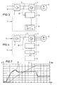
- Figures 3 and 4 show highly schematic embodiments for a drive according to the invention.
- the network is through Lines indicated with L (phase) and N (neutral conductor) are designated.
- a frequency converter is connected to the network 1 connected to the rectifier 2, the Intermediate circuit 3 and the converter 4 comprises.
- the the Control means controlling the converter are denoted by 5. With the three-phase current generated by the converter 4 will the
- Control means 5 with a control signal generator 8 connected, which is a controlled, for example ramping up the speed of the Pump causes.
- the control signal generator 8 is a component of the frequency converter 1.
- the rectifier 2 connected to a three-phase network.
- the pump is opposite the controller of Figure 3 an advantageous alternative shown.
- the frequency converter is with a Interface 7 equipped, one outside of the frequency converter 1 arranged, control signal Unit is connectable. It is dashed as block 9 presented to the myriad of possibilities to indicate.
- the pump can e.g. to a parent Control system for process automation can be connected. With this, among other things Set configurations or adapt (engine speed, ramp-up time, etc.) and error diagnosis options carry out.
- Examples of frequency responses of the converter are in 5 and 6 shown (voltage U versus speed n or frequency Hz). It can be seen that the Frequency responses are independent of whether the frequency judge 1 connected to a 115 V or 230 V network is. It is sufficient if one motor uses 6 is for a fixed, preferably the low Mains voltage range is designed.
- FIG. 7 An example of a particularly useful start-up the pump shows Figure 7.
- the frequency n curve 11
- the torque Nm Curve 12
- the speed increases approximately linearly.
- the torque has a substantially constant value. After reaching the nominal speed the torque (and thus the current consumption of the motor) and is on a lower value kept constant.
- the power supply unit of frequency converter 1 must be (Mains) voltage range 80 to 276 V, the converter 4 for the maximum phase current occurring during operation be conceived.
- the mains voltage detection can preferably from the intermediate circuit voltage, which is proportional to the mains voltage.
- the intermediate circuit 3 is on the line 13 in connection with the control means 5. Based This information can be used to adjust the necessary settings Kink frequency can be changed by software.
- line 13 is over the interface 7 led to the outside, so that the Control signal generator 9 can recognize the mains voltage.
Landscapes
- Engineering & Computer Science (AREA)
- Power Engineering (AREA)
- Control Of Ac Motors In General (AREA)
- Control Of Positive-Displacement Pumps (AREA)
- Control Of Electric Motors In General (AREA)
Description
- Serielle Schnittstelle RS232 / RS485
- Feldbussysteme, z.B. Profibus, LON, Divice-Net
- Analoge u./o. digitale Ein- u. Ausgänge, ggf. potentialfrei bzw. getrennt
- Lichtwellenleitersysteme.
Claims (6)
- Antrieb für eine Vakuumpumpe, dadurch gekennzeichnet, dass der an ein Einphasennetz oder an ein Dreiphasen-(Drehstrom-)Netz anschließbare Antrieb neben dem Motor (6) einen Frequenzumrichter (1) umfaßt, dass der Frequenzumrichter (1) mit einem Gleichrichter (2), mit einem Spannungszwischenkreis (3) und mit einem Stromrichter (4) ausgerüstet ist, dass der Stromrichter (4) mit Steuermitteln in Verbindung steht, dass die Spannung des Zwischenkreises (3) zur Erkennung der Netzspannung verwendet wird und dass sich der Frequenzumrichter (1) automatisch daran anpasst.
- Antrieb nach Anspruch 1, dadurch gekennzeichnet, dass die Steuermittel (5) und Steuersignalgeber (8) Bestandteil des Frequenzumrichters sind.
- Antrieb nach Anspruch 2 , dadurch gekennzeichnet, dass als Steuersignalgeber (8) eine Einheit vorgesehen ist, deren Signale ein gesteuertes, z.B. ein rampenförmiges Hochfahren der Drehzahl bewirken.
- Antrieb nach Anspruch 1, 2 oder 3, dadurch gekennzeichnet, dass der Frequenzumrichter (1) mit einer Schnittstelle (7) ausgerüstet ist, über die ein oder weitere Steuersignalgeber (9) angeschlossen sind.
- Antrieb nach einem der vorhergehenden Ansprüche, dadurch gekennzeichnet, dass der Motor (6) für eine feste Netzspannung ausgelegt ist.
- Antrieb nach Anspruch 5, dadurch gekennzeichnet, dass der Motor (6) für eine niedrige Netzspannung ausgelegt ist.
Applications Claiming Priority (5)
| Application Number | Priority Date | Filing Date | Title |
|---|---|---|---|
| DE19642096 | 1996-10-12 | ||
| DE19642096 | 1996-10-12 | ||
| DE19705672 | 1997-02-14 | ||
| DE19705672A DE19705672A1 (de) | 1996-10-12 | 1997-02-14 | Antrieb für eine Vakuumpumpe |
| PCT/EP1997/005333 WO1998016995A1 (de) | 1996-10-12 | 1997-09-29 | Antrieb für eine vakuumpumpe |
Publications (2)
| Publication Number | Publication Date |
|---|---|
| EP0931378A1 EP0931378A1 (de) | 1999-07-28 |
| EP0931378B1 true EP0931378B1 (de) | 2001-10-31 |
Family
ID=26030279
Family Applications (1)
| Application Number | Title | Priority Date | Filing Date |
|---|---|---|---|
| EP97948757A Expired - Lifetime EP0931378B1 (de) | 1996-10-12 | 1997-09-29 | Antrieb für eine vakuumpumpe |
Country Status (4)
| Country | Link |
|---|---|
| EP (1) | EP0931378B1 (de) |
| JP (1) | JP2001508277A (de) |
| KR (1) | KR100489926B1 (de) |
| WO (1) | WO1998016995A1 (de) |
Families Citing this family (2)
| Publication number | Priority date | Publication date | Assignee | Title |
|---|---|---|---|---|
| JP3711226B2 (ja) | 2000-02-23 | 2005-11-02 | 大日本印刷株式会社 | 真空乾燥装置および真空乾燥方法 |
| JP4558367B2 (ja) * | 2004-03-31 | 2010-10-06 | エドワーズ株式会社 | 真空ポンプ及びその制御方法 |
Family Cites Families (6)
| Publication number | Priority date | Publication date | Assignee | Title |
|---|---|---|---|---|
| JPS61240875A (ja) * | 1985-04-16 | 1986-10-27 | Fanuc Ltd | 三相誘導電動機の制御方法 |
| GB2176667B (en) * | 1985-06-11 | 1989-07-05 | Toshiba Kk | Electric motor running system employing a photovoltaic array |
| JPS63274381A (ja) * | 1987-04-28 | 1988-11-11 | Juki Corp | 電動機の制御装置 |
| US5519301A (en) * | 1992-02-26 | 1996-05-21 | Matsushita Electric Industrial Co., Ltd. | Controlling/driving apparatus for an electrically-driven compressor in a car |
| DE69415774T2 (de) * | 1993-11-09 | 1999-08-05 | Sanyo Electric Co., Ltd., Moriguchi, Osaka | Klimaanlage, verwendbar für einen weiten Bereich von Eingangsspannungen |
| JPH0861287A (ja) * | 1994-08-11 | 1996-03-08 | Ebara Corp | ポンプ用インバータユニット及びそのユニットを備えたポンプ装置 |
-
1997
- 1997-09-29 KR KR10-1999-7003156A patent/KR100489926B1/ko not_active Expired - Fee Related
- 1997-09-29 WO PCT/EP1997/005333 patent/WO1998016995A1/de not_active Ceased
- 1997-09-29 JP JP51796498A patent/JP2001508277A/ja active Pending
- 1997-09-29 EP EP97948757A patent/EP0931378B1/de not_active Expired - Lifetime
Also Published As
| Publication number | Publication date |
|---|---|
| WO1998016995A1 (de) | 1998-04-23 |
| EP0931378A1 (de) | 1999-07-28 |
| KR100489926B1 (ko) | 2005-05-17 |
| JP2001508277A (ja) | 2001-06-19 |
| KR20000049081A (ko) | 2000-07-25 |
Similar Documents
| Publication | Publication Date | Title |
|---|---|---|
| DE69433429T2 (de) | Klimaanlage für einen weiten Bereich von Eingangsspannungen | |
| DE602004004496T2 (de) | Energieverbrauch in einem elektrischen Antrieb | |
| DE3420144A1 (de) | Regelungs- und steuerungssystem, insbes. fuer wassering-vakuumpumpen | |
| EP2708825B1 (de) | Verfahren zum Steuern einer Umwälzpumpe in einer Anlage mit mindestens zwei Umwälzkreisen | |
| DE69004566T2 (de) | Vakuumpumpeneinheit. | |
| EP0743578A1 (de) | Reinraumanlage | |
| DE112017003164T5 (de) | Selektiv konfigurierbarer bürstenloser gs-motor | |
| DE10300174B3 (de) | Windenergieanlage mit mindestens zwei Komponenten und einem Datennetz | |
| WO1996025787A1 (de) | Antrieb mit einem drehstrom-asynchronmotor mit schleifringläufer | |
| DE4410735B4 (de) | Einrichtung mit einem Feuerungsautomaten | |
| DE19705672A1 (de) | Antrieb für eine Vakuumpumpe | |
| EP3383789B1 (de) | Seildurchlaufwinde | |
| DE3049200C2 (de) | Mit einem Wechselstrom-Antriebsmotor ausgerüsteter Schrauber | |
| EP0931378A1 (de) | Antrieb für eine vakuumpumpe | |
| EP3400645B1 (de) | Vakuumpumpenantrieb mit stern-dreieck-umschaltung | |
| DE10032762B4 (de) | "Gargerät mit Spannungs-,Phasen-und /oder Frequenzumwandler" | |
| WO1997048178A1 (de) | Anordnung mit einem elektronisch kommutierten motor | |
| WO2014009375A2 (de) | Verfahren zum steuern einer vakuumpumpe | |
| EP1969713B1 (de) | Überwachungseinheit zur lastüberwachung eines elektrischen motors | |
| DE19642097A1 (de) | Antrieb für eine ölgedichtete Vakuumpumpe, insbesondere Drehschiebervakuumpumpe | |
| EP2383879A2 (de) | Verfahren und Synchronisationseinrichtung zur Synchronisierung von mindestens zwei RWA- und Lüftungsklappenantrieben | |
| DE102005045284A1 (de) | Drehzahlüberwachungsvorrichtung | |
| EP2082491B1 (de) | Anlage und verfahren zum betreiben einer anlage | |
| EP3676950B1 (de) | Adaptiver stellantrieb zum betrieb an einer drei- oder vieradrigen externen steuerleitung mit unterschiedlichen motorspannungen und netzfrequenzen sowie geeignete verwendung | |
| EP1493218B1 (de) | Not-aus-system für induktiv versorgte verbraucher |
Legal Events
| Date | Code | Title | Description |
|---|---|---|---|
| PUAI | Public reference made under article 153(3) epc to a published international application that has entered the european phase |
Free format text: ORIGINAL CODE: 0009012 |
|
| 17P | Request for examination filed |
Effective date: 19990225 |
|
| AK | Designated contracting states |
Kind code of ref document: A1 Designated state(s): DE FR GB IT |
|
| 17Q | First examination report despatched |
Effective date: 19990806 |
|
| GRAG | Despatch of communication of intention to grant |
Free format text: ORIGINAL CODE: EPIDOS AGRA |
|
| GRAG | Despatch of communication of intention to grant |
Free format text: ORIGINAL CODE: EPIDOS AGRA |
|
| GRAH | Despatch of communication of intention to grant a patent |
Free format text: ORIGINAL CODE: EPIDOS IGRA |
|
| GRAH | Despatch of communication of intention to grant a patent |
Free format text: ORIGINAL CODE: EPIDOS IGRA |
|
| GRAA | (expected) grant |
Free format text: ORIGINAL CODE: 0009210 |
|
| AK | Designated contracting states |
Kind code of ref document: B1 Designated state(s): DE FR GB IT |
|
| REF | Corresponds to: |
Ref document number: 59705217 Country of ref document: DE Date of ref document: 20011206 |
|
| REG | Reference to a national code |
Ref country code: GB Ref legal event code: IF02 |
|
| GBT | Gb: translation of ep patent filed (gb section 77(6)(a)/1977) |
Effective date: 20020107 |
|
| PLBE | No opposition filed within time limit |
Free format text: ORIGINAL CODE: 0009261 |
|
| STAA | Information on the status of an ep patent application or granted ep patent |
Free format text: STATUS: NO OPPOSITION FILED WITHIN TIME LIMIT |
|
| 26N | No opposition filed | ||
| PGFP | Annual fee paid to national office [announced via postgrant information from national office to epo] |
Ref country code: IT Payment date: 20100923 Year of fee payment: 14 |
|
| PGFP | Annual fee paid to national office [announced via postgrant information from national office to epo] |
Ref country code: DE Payment date: 20101125 Year of fee payment: 14 |
|
| PGFP | Annual fee paid to national office [announced via postgrant information from national office to epo] |
Ref country code: FR Payment date: 20111005 Year of fee payment: 15 Ref country code: GB Payment date: 20110923 Year of fee payment: 15 |
|
| GBPC | Gb: european patent ceased through non-payment of renewal fee |
Effective date: 20120929 |
|
| REG | Reference to a national code |
Ref country code: FR Ref legal event code: ST Effective date: 20130531 |
|
| PG25 | Lapsed in a contracting state [announced via postgrant information from national office to epo] |
Ref country code: DE Free format text: LAPSE BECAUSE OF NON-PAYMENT OF DUE FEES Effective date: 20130403 Ref country code: GB Free format text: LAPSE BECAUSE OF NON-PAYMENT OF DUE FEES Effective date: 20120929 |
|
| REG | Reference to a national code |
Ref country code: DE Ref legal event code: R119 Ref document number: 59705217 Country of ref document: DE Effective date: 20130403 |
|
| PG25 | Lapsed in a contracting state [announced via postgrant information from national office to epo] |
Ref country code: FR Free format text: LAPSE BECAUSE OF NON-PAYMENT OF DUE FEES Effective date: 20121001 Ref country code: IT Free format text: LAPSE BECAUSE OF NON-PAYMENT OF DUE FEES Effective date: 20120929 |