EP0931449A1 - Presse avec dispositif d'enveloppage - Google Patents
Presse avec dispositif d'enveloppage Download PDFInfo
- Publication number
- EP0931449A1 EP0931449A1 EP98124689A EP98124689A EP0931449A1 EP 0931449 A1 EP0931449 A1 EP 0931449A1 EP 98124689 A EP98124689 A EP 98124689A EP 98124689 A EP98124689 A EP 98124689A EP 0931449 A1 EP0931449 A1 EP 0931449A1
- Authority
- EP
- European Patent Office
- Prior art keywords
- bale
- roller
- wrapping material
- press according
- side walls
- Prior art date
- Legal status (The legal status is an assumption and is not a legal conclusion. Google has not performed a legal analysis and makes no representation as to the accuracy of the status listed.)
- Granted
Links
- 239000000463 material Substances 0.000 claims abstract description 120
- 230000015572 biosynthetic process Effects 0.000 claims abstract description 12
- 238000003892 spreading Methods 0.000 claims description 40
- 238000004804 winding Methods 0.000 claims description 31
- 239000003795 chemical substances by application Substances 0.000 claims description 3
- 230000002093 peripheral effect Effects 0.000 claims description 3
- 238000007493 shaping process Methods 0.000 claims description 3
- 229920001169 thermoplastic Polymers 0.000 claims description 3
- 239000004416 thermosoftening plastic Substances 0.000 claims description 3
- 238000011144 upstream manufacturing Methods 0.000 claims 2
- 238000010276 construction Methods 0.000 abstract description 2
- 239000010902 straw Substances 0.000 abstract 1
- 238000001514 detection method Methods 0.000 description 3
- 238000005520 cutting process Methods 0.000 description 2
- 238000004146 energy storage Methods 0.000 description 2
- 230000033001 locomotion Effects 0.000 description 2
- 239000002184 metal Substances 0.000 description 2
- 238000000034 method Methods 0.000 description 2
- 238000009825 accumulation Methods 0.000 description 1
- 238000005452 bending Methods 0.000 description 1
- 230000005540 biological transmission Effects 0.000 description 1
- 230000006835 compression Effects 0.000 description 1
- 238000007906 compression Methods 0.000 description 1
- 230000001419 dependent effect Effects 0.000 description 1
- 238000011161 development Methods 0.000 description 1
- 230000018109 developmental process Effects 0.000 description 1
- 230000026058 directional locomotion Effects 0.000 description 1
- 230000000694 effects Effects 0.000 description 1
- 238000003306 harvesting Methods 0.000 description 1
- 230000003116 impacting effect Effects 0.000 description 1
- 238000003780 insertion Methods 0.000 description 1
- 230000037431 insertion Effects 0.000 description 1
- 238000009434 installation Methods 0.000 description 1
- 238000003825 pressing Methods 0.000 description 1
- 230000002940 repellent Effects 0.000 description 1
- 239000005871 repellent Substances 0.000 description 1
- 238000000926 separation method Methods 0.000 description 1
- 239000007858 starting material Substances 0.000 description 1
- 210000001364 upper extremity Anatomy 0.000 description 1
- XLYOFNOQVPJJNP-UHFFFAOYSA-N water Substances O XLYOFNOQVPJJNP-UHFFFAOYSA-N 0.000 description 1
Images


Classifications
-
- A—HUMAN NECESSITIES
- A01—AGRICULTURE; FORESTRY; ANIMAL HUSBANDRY; HUNTING; TRAPPING; FISHING
- A01F—PROCESSING OF HARVESTED PRODUCE; HAY OR STRAW PRESSES; DEVICES FOR STORING AGRICULTURAL OR HORTICULTURAL PRODUCE
- A01F15/00—Baling presses for straw, hay or the like
- A01F15/07—Rotobalers, i.e. machines for forming cylindrical bales by winding and pressing
- A01F15/071—Wrapping devices
- A01F15/0715—Wrapping the bale in the press chamber before opening said chamber
- A01F2015/072—Braking means for the film roll in balers which wrap the bale before opening the pressing chamber in order to stretch the film while wrapping
Definitions
- the side wall itself can also be attached accordingly be formed. This can be done by an appropriate Shaping, d. H. by pressing or bending, or by Inserts can be achieved.
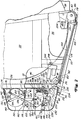
- a press 10 of the large type manufactures cylindrical bales and generally as one large round baler is called.
- the press 10 contains a frame 12 carried by a pair of bottom wheels 14 , of which only the left bottom wheel 14 is shown.
- a Drawbar 16 which is designed so that it connects to one Agricultural tractors can be connected to the frame 12 fixed.
- a pair in the cross direction a distance side walls 18 facing one another is with the frame 12 connected and has rear upright end portions.
- a Bale discharge gate 20 with opposing side walls 22 is vertically pivotable in a pivot connection 24 attached to upper rear positions of the side walls 18, the side walls 22 having front end portions which strike against the rear end regions of the side walls 18, when the bale discharge gate 20 is in a lower closed position as shown is.
- the pair of side walls 18 and 22 take each other opposite end portions of a plurality of support rollers for the straps to form bales that are close to the Outside of the side walls 18, 22 are located.
- a plurality of endless belts 42 to form one Bale is provided between the pair of side walls 18 and 22 and carried side by side by the different roles.
- the Harvested crop is fed into the crop inlet 60 by means of a pick-up 62 introduced to a bale, such as bale 58, to be rolled up due to the effect of front and rear dreams 44 and 46 of straps 42, which are each driven so that they become the Move inlet 60 to and from it, and initially also from a starter roller 64 that is near the driven Roller 26 is rotatably received in the side walls 18 and in the same direction as this is driven so that it Strips the crop from the front run 44 of the straps 42 is taken down.
- a pick-up 62 introduced to a bale, such as bale 58, to be rolled up due to the effect of front and rear dreams 44 and 46 of straps 42, which are each driven so that they become the Move inlet 60 to and from it, and initially also from a starter roller 64 that is near the driven Roller 26 is rotatably received in the side walls 18 and in the same direction as this is driven so that it Strips the crop from the front run 44 of the straps 42 is taken down.
- the winder 70 includes a support frame that is on the lower half of the rear of the bale unloading gate 20 is mounted and a transverse vertical wall 72 which extends between vertical flanges and attached to this, which is the rear ends of the opposite side walls 22 of the bale unloading gate 20 form.
- the wall 72 has an upper end portion which is from a downward and rearward flange 74 is formed.
- Corresponding transverse legs of one Pairs of angular bracket 76 for supporting lever arms are at upper right and left areas of wall 72 below the flange 74 screwed.
- a pair of angular supports 80 for holding clamping arms is at a vertical distance provided to the pair of holders 76 downward and has transversely extending legs which are screwed to the wall 72.
- the support frame of the winder 70 also includes a A pair of longitudinally extending vertical support walls 84, which in the side view is approximately rectangular and the front one have vertical sides that are transverse Flanges are formed that form a lower area of the wall 72 overlap and by means of threads, not shown having fasteners on the structure in the rear Area of the bale discharge gate 20 are attached so as to to have a distance from one another in the transverse direction which is greater than the distance between the side walls 22 of the Bale unloading gate 20, d. H. larger than the width of the Bale forming chamber 56.
- a pair of feed rollers 86 and 88 for the wrapping material extends between the support walls 84 and is with its opposite end regions rotatably supported in these, the feed roller 86 opposite the feed roller 88 is arranged offset at the top and rear, in such a way that a trajectory defined by a plane that is in the Area of the gap tangent to the feed rollers 86, 88 extends, runs under the wall 72 and on a vertical run of the straps 42 that meets between the upper and lower straps 42 carrying Roll 36 or 38 extends.
- the trajectory of the wrapping material cuts the straps 42 at a location above one Detection point 90 by an area of a Wrapper tray 92 which is part of a wrapper guide assembly 93 forms, and an area of Belt 42 is formed which engages the lower rear roll 38 stands.
- the upper feed roller 86 for the Wrapping material is arranged so that it is on the lower Feed roller 88 is tensioned for the winding material.
- in the individual is a U-shaped on the outside of each of the support walls 84 Holder 94 attached.
- the thread ends of a pair of eyelet-like clamps 95 each run upwards through the pair of holders 94 and are in one set position held by a nut 96.
- a Spring 98 designed as a spiral spring is on each clamping bracket 95 arranged below the associated holder 94, and one Nut 100 loads each spring 98 with respect to the associated holder 94.
- a holding bolt 104 which serves to to mount the feed roller 86 rotatably on the tensioning bracket 95 and this toward and away from the lower feed roller 88 as far as allowed by slots 102, extends through the eyelet of each clamp 95 and through a slot 102 for adjustment purposes in the adjacent one Support wall 84.
- the upper feed roller 86 is preferably of the type Metal roll formed, which is coated with rubber, and is, as is apparent from Figure 2, against the Clockwise direction of rotation driven.
- the drive of the feed roller 86 is in a conventional manner not shown as Belt transmission with one variable pulley and one Pulley formed which is attached to a shaft connected as an extension of the lower roller 38 is so that there is always a direct relationship between the Belt 42 speed and peripheral speed the feed rollers 86, 88 for the winding material to thus a relatively high tension in the winding material during of wrapping around the bale 58 Voltage is ideally as high as it can be without the wrapping material tears or while handling the wrapped bale 58 is subject to the risk of tearing.
- Material roll 112 is temporarily held by a pair of ramps 114 worn, each inclined downwards and forwards across extend from the support walls 84, in places that move the ramps 114 into a level that is slightly extends above the axis of rotation of the upper feed roller 86, the feed roller 86 being the main or only one Support for the material roll 112 is used.
- a tensioner 116 provided a pair a transverse distance from each other having arms 118, the front end portions to the pair of supports 80 by means of a pair of bolts 120 are pivotally attached.
- a roller 122 is rotatable in the rear end portions of the arms 118 and so on arranged that they can rotate freely and substantially a slight rubbing engagement with the upper rear Maintains quadrants of the roll of material 112 when the Roll of material 112 becomes smaller when the winding material is added is used to wrap the bale 58.
- the jig 116 also includes a pair of links 124, the lower one End portions each on a pair of pins 126 attached to the arms 118 are welded, pivotally received, and their upper end regions each pivotable somewhat by means of pins 128 to rear legs of a pair of lever arms 130 are attached, each itself by means of bolts 132 the pair of holders 76 are pivotally connected.
- a compliant force to press the roller 122 against the Roll of material 112 with the winding material is one pair Energy storage 134 in the manner of gas pressure cylinders applied, the rod ends each by means of a Pair of pins 136 on front legs of the pair of Lever arms 130 are pivotally attached, and their Each cylinder ends, for example, by means of a pair of pins 138 on opposite side walls of a cover 140 are pivotally connected.
- the lid 140 has an upper wall that pivotable on the flange 74 by means of a hinge 142 is attached, which allows the lid 140 from a lower closed position, as in solid Lines are shown and in the upright front ends of the Side walls on the rear of the bale unloading gate 20 in a raised position by one Angle is pivoted, starting from the closed Position is more than 90 degrees.
- the roll 122 against the roll of material 112 of the winding material is the geometric relationship between the line of action the energy accumulator 134 and the pins 132 of the lever arms 130 such that the energy storage 134 over a Move the dead center position and the cover 140 in its open Keep position tense.
- the lid 140 is by means of a Latch 144 held releasably in its closed position, that in an opening of an angular bar holder 146 is recorded, which is between the support walls 84th extends and is connected to these.
- a locking lever 148 is at a central location on a rear wall of the cover 140 pivotally attached and so operable that it has the latch 144 either out or in a locked connection with the Bar holder 146 moves.
- a supply roll 150 for the winding material is above and stored in close proximity to the material roll 112.
- Supports for carrying the supply roll 150 contain a pair upright leg 152, each turned outward
- Have end areas secured to horizontal flanges are, which form upper sides of the support walls 84.
- the connection each leg 152 is with the associated support wall 84 compliant and is made using a screw 154, which are through corresponding holes in the leg end and the flange of the support wall 84 and one as one Spiral compression spring trained spring 156, which means a nut 158 on the lower end portion of the screw 154 is kept stationary.
- the arms 118 will then lowered so that the roller 122 the new material roller 112th touched.
- the roller loading supports 161 are then returned to their Waiting position, the legs 152 are in their Operating positions brought and the lid 140 is closed. If it is appropriate, the removed one
- the supply roll 150 is replaced by the cover 140 is opened, the roller loading supports 161 in their loading positions brought, a new supply roll 150 on the Roller loading supports 161 rolled and the new supply roll 150 from there end by end if desired the shelves 160 is raised.
- the lid 140 is then in lowered its closing position.
- each Manhole section 174 strikes an inverted U-shaped one Manhole part 176 and is welded to it, which itself immediately below the rear roller 38 for the straps 42 is located.
- the front end portion of each manhole part 176 ends just below the front roller 40 and its Flanges are circularly recessed to go on top a cylindrical cross member 178 placed to with this to be able to be welded and was in one place that is behind the roller 40.
- the opposite End portions of cross member 178 are each on the pair front bracket 170 connected.
- the wrapping material guide trough 92 projects over upper surfaces of each shaft part 174 and 176 and is attached to and extends from the Manhole part 176 from back to a point near the Back of the bale unloading gate 20.
- the wrapping material 162 extends below the roller 38 and through the Detection point 90 between the belt 42 and the Wrapping material guide trough 92 is formed.
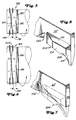
- FIG. 5 shows the rear right spreading roller 182, in the form of a cylindrical tube or sleeve that are provided with a pair of spiral grooves 190 which diametrically opposite locations at the inner ends of the Start the roll and end at 180 degrees to the starting point.
- a flat continuous area 192 extends from the Spiral grooves 190 axially outward and is made by a pair separate spiral bars 194 followed, essentially on opposite areas of the roller are arranged, wherein however, each spiral web 194 opposite end regions contains the middle section of the other spiral bridge 194 overlap and run parallel to it.
- the slope the spiral grooves 190 and the spiral webs 194 is such that they tend to face the opposite sides of the Section of the wrapping material 162 to move outward and against any tendency of the wrapping material 162 due to the tension exerted on it during bale wrapping is going to narrow.
- the front right spreading roller 186 is shown in FIG. 6 and with a pair of spiral grooves 196, a flat area 198 and a pair of spiral bars 200, each with the spiral grooves 190, the flat area 192 and the Spiral bars 194 of the rear right spreading roller 182 are the same.
- Left and right guide plates 202 and 204 each on the side walls 22 near the spreading rollers 186 and 188 are attached where the portion of wrapping material 162 in the good inlet 60 of the bale forming chamber 56 acts each with the front right and left spreading rollers 186 and 188 together to ensure that the portion of the Brought wrapping material 162 over the corners of the bale 58 becomes.
- the purpose of the guide plates 202 and 204 is four times.
- the guide plates 202 and 204 each have lower edges 220, which contain front areas, each one extend arcuately around the spreading rollers 186 and 188, and in a very narrow but spaced-apart manner from that flat continuous area 198 of spreading rollers 186, 188.
- the above fourth purpose of the guide plates 202, 204 is by means of a guide element 228, which acts as a deflector or Scraper works, reaching that from the front vertical edge 212 (FIG. 4) of each guide plate 202, 204 extends transversely and outwards so as to lay in front of the associated spreading roller 186 or 188 to take the Probability eliminated or reduced that Harvested crop that is 60 in through the crop inlet by means of the pick-up 62 the bale forming chamber 56 is guided around the spreading rollers 186 and 188 wraps where it feeds the section of the Wrapping material 162 could collide.
- the guide elements 228 are here in a substantially triangular shape in the Front view shown but could be any other shape have, which is suitable to the desired function provide.
- separator 232 actuated to the stretched wrapping material 162 on a Place between the feed rollers 86 and 88 and the Detect detection point 90 between the straps 42 and the wrapping material guide assembly 92 is formed.
- separator 232 contains in particular a fixed knife 234, which transversely extends between the vertical support walls 84 and one after has cutting edge 236 which faces directly extends below the path from the section of the Wrapping material 162 is taken.
- the guide plates 202, 204 which here at the Use in a resizable bale forming chamber 56 with belt 42 are shown, also in a fixed chamber press used where they are close to rotatable bale forming agents near the inlet for the wrapping material 162 be arranged, which is not necessarily the Is crop inlet.
- the function of the Guide plates 202 and 204 through the use of Guide plates are achieved that are like the guide plate 204 'together with a modified side wall 22' are formed, the instead of the guide plate Side wall is provided with an opening to the outer Edge region of the section of the winding material 162 for winding over the ends of bale 58 into bale forming chamber 56 let in. The same applies to those in FIG.
Landscapes
- Life Sciences & Earth Sciences (AREA)
- Environmental Sciences (AREA)
- Storage Of Harvested Produce (AREA)
- Controlling Rewinding, Feeding, Winding, Or Abnormalities Of Webs (AREA)
Applications Claiming Priority (2)
| Application Number | Priority Date | Filing Date | Title |
|---|---|---|---|
| US09/008,515 US6006504A (en) | 1998-01-16 | 1998-01-16 | Large round baler having wrapping mechanism for placing net over edges of bale |
| US8515 | 1998-01-16 |
Publications (2)
| Publication Number | Publication Date |
|---|---|
| EP0931449A1 true EP0931449A1 (fr) | 1999-07-28 |
| EP0931449B1 EP0931449B1 (fr) | 2001-06-13 |
Family
ID=21732035
Family Applications (1)
| Application Number | Title | Priority Date | Filing Date |
|---|---|---|---|
| EP98124689A Expired - Lifetime EP0931449B1 (fr) | 1998-01-16 | 1998-12-24 | Presse avec dispositif d'enveloppage |
Country Status (6)
| Country | Link |
|---|---|
| US (1) | US6006504A (fr) |
| EP (1) | EP0931449B1 (fr) |
| AU (1) | AU744122B2 (fr) |
| CA (1) | CA2244201C (fr) |
| DE (1) | DE59800840D1 (fr) |
| ES (1) | ES2157637T3 (fr) |
Cited By (6)
| Publication number | Priority date | Publication date | Assignee | Title |
|---|---|---|---|---|
| EP1099367A1 (fr) * | 1999-11-12 | 2001-05-16 | Deere & Company | Dispositif d'alimentation de gaine pour enrubannage |
| EP1829445A1 (fr) * | 2006-03-03 | 2007-09-05 | Deere & Company | Presse à empaqueter |
| DE102006049139B4 (de) * | 2006-10-18 | 2012-12-06 | Welger Maschinenfabrik Gmbh | Rundballenpresse für landwirtschaftliche Halmgüter mit einer Umhüllvorrichtung |
| EP2266386A3 (fr) * | 2003-07-31 | 2014-01-15 | Kuhn-Geldrop B.V. | Dispositif d'alimentation pour l'amenée d'une feuille de couverture destinée à recouvrir la face externe d'une botte agricole |
| US11491752B2 (en) | 2018-11-01 | 2022-11-08 | Signode Industrial Group Llc | Press-type strapping machine with improved top-platen control |
| US12612202B2 (en) | 2021-07-29 | 2026-04-28 | Signode Industrial Group Llc | System for compressing and strapping loads with press-type strapping machines having improved platen control |
Families Citing this family (34)
| Publication number | Priority date | Publication date | Assignee | Title |
|---|---|---|---|---|
| US6622463B1 (en) * | 1999-11-30 | 2003-09-23 | Deere & Company | Device for folding leading end of net-type bale wrapping material to enhance its full-width conveyance into the baling chamber |
| US6606843B1 (en) | 2000-03-21 | 2003-08-19 | Deere & Company | Structure for reliably feeding and spreading net wrap material, of a width greater than the width of a round baler chamber, so as to cover opposite end segments of a bale located in the chamber |
| DE10026066A1 (de) * | 2000-05-25 | 2001-11-29 | Deere & Co | Vorrichtung zum Umhüllen eines Rundballens |
| US6477824B2 (en) * | 2001-01-24 | 2002-11-12 | Agco Corporation | Round baler having incoming crop deflectors |
| US6550218B2 (en) * | 2001-06-08 | 2003-04-22 | New Holland North America, Inc. | Over the edge net wrap dispensing system for a round baler |
| DE10211412A1 (de) * | 2002-03-15 | 2003-10-09 | Deere & Co | Rundballenpresse |
| NO320359B1 (no) * | 2003-09-16 | 2005-11-28 | Kverneland Group Operations No | Anordning ved rundballepresse og fremgangsmate ved bruk av samme |
| US7181900B2 (en) * | 2003-11-21 | 2007-02-27 | Vermeer Manufacturing Co. | Netwrap feed and cut mechanism |
| US8147472B2 (en) | 2003-11-24 | 2012-04-03 | Kimberly-Clark Worldwide, Inc. | Folded absorbent product |
| US7409814B2 (en) * | 2004-09-07 | 2008-08-12 | Vermeer Manufacturing Company | Method of initiating automatic feed of bale wrapping material |
| CA2611754C (fr) * | 2005-06-10 | 2012-06-05 | Rpp America, Llc | Presse a balles haute compression |
| EP1772408A1 (fr) | 2005-10-04 | 2007-04-11 | CNH Belgium N.V. | Dispositif d'emballage de balles rondes à enfilage automatique |
| US7191699B1 (en) * | 2006-05-30 | 2007-03-20 | Deere & Company | Shield for preventing crop build-up affecting gate closure on round baler |
| GB2438610A (en) * | 2006-06-02 | 2007-12-05 | Cnh Belgium Nv | Round baler with changeable wrapping width |
| US8429881B2 (en) * | 2009-09-18 | 2013-04-30 | Agco Corporation | Baler starter roll |
| EP2387874A1 (fr) * | 2010-05-17 | 2011-11-23 | Deere & Company | Ralenti avec un déflecteur et dispositif d'enveloppement par toile |
| EP2632242A2 (fr) | 2010-10-29 | 2013-09-04 | Forage Innovations B.V. | Cale rotative de retenue du foin pour des ramasseuses-presses de balles rondes |
| US9706716B2 (en) * | 2012-08-21 | 2017-07-18 | Cnh Industrial America Llc | Current sensing of actuators on a round baler |
| US10440894B2 (en) * | 2013-08-14 | 2019-10-15 | Deere & Company | Wrap device for a round module builder |
| US10440895B2 (en) * | 2015-08-17 | 2019-10-15 | Deere & Company | Motor-drive for application of wrap material to crop packages |
| EP3289855B1 (fr) * | 2016-09-04 | 2023-07-05 | CNH Industrial Belgium nv | Système d'embout pour un rouleau déplisseur |
| US11039575B2 (en) * | 2017-02-24 | 2021-06-22 | Deere & Company | External belt guide for round baler |
| US11032974B2 (en) * | 2017-02-24 | 2021-06-15 | Deere & Company | External belt guide for round baler |
| US10736272B2 (en) | 2018-03-09 | 2020-08-11 | Deere & Company | Material wrap system with automatic drive tension compensation |
| US10888048B2 (en) * | 2018-03-15 | 2021-01-12 | Deere & Company | Material wrap system with self cleaning feature |
| US10912257B2 (en) * | 2019-02-22 | 2021-02-09 | Deere & Company | Wrap feed assembly for round module builder |
| US11140831B2 (en) * | 2019-03-13 | 2021-10-12 | Deere & Company | Wrap material supply systems for usage in agricultural baling machines |
| US11375669B2 (en) | 2019-05-20 | 2022-07-05 | Deere & Company | Positive drive wrap delivery system |
| US12232453B2 (en) * | 2022-05-18 | 2025-02-25 | Agco Corporation | Agricultural baler |
| CN115399147B (zh) * | 2022-09-27 | 2023-04-07 | 黑龙江德沃科技开发有限公司 | 一种圆草捆边缘修形板及其安装使用方法 |
| US12582046B2 (en) * | 2023-07-28 | 2026-03-24 | Deere & Company | Nip system in a module wrap feed arrangement |
| US12477997B2 (en) | 2023-10-31 | 2025-11-25 | Cnh Industrial Canada, Ltd. | Bale wrap assembly loading system for an agricultural harvester |
| CN120858755A (zh) * | 2024-04-30 | 2025-10-31 | 凯斯纽荷兰工业美国有限责任公司 | 用于农业收割机的捆包包裹物组件管理系统 |
| US20260033433A1 (en) * | 2024-08-05 | 2026-02-05 | Deere & Company | Wrap material guide for spool roller of a baler implement |
Citations (4)
| Publication number | Priority date | Publication date | Assignee | Title |
|---|---|---|---|---|
| EP0314923A1 (fr) * | 1987-10-31 | 1989-05-10 | Deere & Company | Méthode et machine pour envelopper un produit compressé |
| US4917008A (en) | 1987-08-21 | 1990-04-17 | P.J. Zweegers En Zonen Landbouwmachinefabriek B.V. | Baling material and baling device for making baled articles |
| US5090182A (en) * | 1989-12-02 | 1992-02-25 | Claas Ohg | Round bale press for agricultural products |
| US5104714A (en) | 1989-11-30 | 1992-04-14 | Tama Plastic Industry | Elastic plastic netting made of oriented strands |
Family Cites Families (5)
| Publication number | Priority date | Publication date | Assignee | Title |
|---|---|---|---|---|
| SE407677B (sv) * | 1976-10-18 | 1979-04-09 | Gustavsson Olov Erland | Sett och apparat for att forma ett skyddande holje kring ett prismatiskt eller cylindriskt foremal |
| DE3234748A1 (de) * | 1982-09-20 | 1984-03-22 | Gebrüder Welger GmbH & Co KG, 3340 Wolfenbüttel | Rollballenpresse mit festen seitenwaenden |
| US4790125A (en) * | 1987-05-01 | 1988-12-13 | New Holland Inc. | Feed rollers for round baler net dispenser |
| US4969315A (en) * | 1989-03-24 | 1990-11-13 | Deere & Company | Structure for guiding surface wrap into a bale chamber |
| JP2819334B2 (ja) * | 1990-01-31 | 1998-10-30 | 良三 松本 | 包装装置 |
-
1998
- 1998-01-16 US US09/008,515 patent/US6006504A/en not_active Expired - Lifetime
- 1998-09-08 CA CA002244201A patent/CA2244201C/fr not_active Expired - Fee Related
- 1998-12-08 AU AU96138/98A patent/AU744122B2/en not_active Ceased
- 1998-12-24 EP EP98124689A patent/EP0931449B1/fr not_active Expired - Lifetime
- 1998-12-24 DE DE59800840T patent/DE59800840D1/de not_active Expired - Lifetime
- 1998-12-24 ES ES98124689T patent/ES2157637T3/es not_active Expired - Lifetime
Patent Citations (4)
| Publication number | Priority date | Publication date | Assignee | Title |
|---|---|---|---|---|
| US4917008A (en) | 1987-08-21 | 1990-04-17 | P.J. Zweegers En Zonen Landbouwmachinefabriek B.V. | Baling material and baling device for making baled articles |
| EP0314923A1 (fr) * | 1987-10-31 | 1989-05-10 | Deere & Company | Méthode et machine pour envelopper un produit compressé |
| US5104714A (en) | 1989-11-30 | 1992-04-14 | Tama Plastic Industry | Elastic plastic netting made of oriented strands |
| US5090182A (en) * | 1989-12-02 | 1992-02-25 | Claas Ohg | Round bale press for agricultural products |
Cited By (6)
| Publication number | Priority date | Publication date | Assignee | Title |
|---|---|---|---|---|
| EP1099367A1 (fr) * | 1999-11-12 | 2001-05-16 | Deere & Company | Dispositif d'alimentation de gaine pour enrubannage |
| EP2266386A3 (fr) * | 2003-07-31 | 2014-01-15 | Kuhn-Geldrop B.V. | Dispositif d'alimentation pour l'amenée d'une feuille de couverture destinée à recouvrir la face externe d'une botte agricole |
| EP1829445A1 (fr) * | 2006-03-03 | 2007-09-05 | Deere & Company | Presse à empaqueter |
| DE102006049139B4 (de) * | 2006-10-18 | 2012-12-06 | Welger Maschinenfabrik Gmbh | Rundballenpresse für landwirtschaftliche Halmgüter mit einer Umhüllvorrichtung |
| US11491752B2 (en) | 2018-11-01 | 2022-11-08 | Signode Industrial Group Llc | Press-type strapping machine with improved top-platen control |
| US12612202B2 (en) | 2021-07-29 | 2026-04-28 | Signode Industrial Group Llc | System for compressing and strapping loads with press-type strapping machines having improved platen control |
Also Published As
| Publication number | Publication date |
|---|---|
| EP0931449B1 (fr) | 2001-06-13 |
| CA2244201C (fr) | 2002-02-26 |
| AU744122B2 (en) | 2002-02-14 |
| AU9613898A (en) | 1999-08-05 |
| US6006504A (en) | 1999-12-28 |
| DE59800840D1 (de) | 2001-07-19 |
| CA2244201A1 (fr) | 1999-07-16 |
| ES2157637T3 (es) | 2001-08-16 |
Similar Documents
| Publication | Publication Date | Title |
|---|---|---|
| EP0931449B1 (fr) | Presse avec dispositif d'enveloppage | |
| DE69909188T2 (de) | Umhüllungsvorrichtung für Rundballen | |
| EP0941651B1 (fr) | Dispositif d'enveloppage d'une presse | |
| EP0935915B1 (fr) | Dispositif d'enveloppage d'une presse avec un rouleau d'alimentation et un rouleau d'approvisionnement | |
| EP1099366B1 (fr) | Dispositif d'alimentation de gaine pour enrubannage | |
| DE2851035C2 (de) | Erntegut-Rundballenformmaschine | |
| DE69707050T2 (de) | Ernteaufsammeleinrichtung | |
| EP1214875A1 (fr) | Presse à balles rondes | |
| DE10006384A1 (de) | Rundballenpresse | |
| DE10112685A1 (de) | Rundballenpresse | |
| DE2443838A1 (de) | Rollballenpresse | |
| DE69308059T2 (de) | Walzenabstreifeinrichtung für eine Rundballenpresse | |
| EP1214874A1 (fr) | Presse à balles rondes | |
| EP0655189A1 (fr) | Presse à faire des balles cylindriques | |
| DE2530249B2 (de) | Wickelballenpresse | |
| DE3223784A1 (de) | Ausstossmechanismus fuer eine rundballenpresse | |
| DE2947388C2 (fr) | ||
| DE2537121A1 (de) | Vorrichtung zum fuehren und zentrieren eines foerderbandes in einer rundballenpresse | |
| EP0404094A1 (fr) | Presse à balles rondes avec un dispositif pour envelopper une balle ronde enroulée dans une chambre de formation de balles rondes | |
| DE3734186A1 (de) | Aufsammel-rollballenpresse | |
| DE4215308C2 (de) | Rundballenpresse | |
| EP0095689B1 (fr) | Presse à balles rondes dont la chambre de compactage comprend une entrée pour le matériau | |
| DE68906068T2 (de) | Rundballenpresse mit variabler kammer und schleppvorrichtung. | |
| DE10063120A1 (de) | Rundballenpresse | |
| DE3607040A1 (de) | Rollballenpresse |
Legal Events
| Date | Code | Title | Description |
|---|---|---|---|
| PUAI | Public reference made under article 153(3) epc to a published international application that has entered the european phase |
Free format text: ORIGINAL CODE: 0009012 |
|
| AK | Designated contracting states |
Kind code of ref document: A1 Designated state(s): DE ES FR GB IT |
|
| AX | Request for extension of the european patent |
Free format text: AL;LT;LV;MK;RO;SI |
|
| 17P | Request for examination filed |
Effective date: 19991218 |
|
| AKX | Designation fees paid |
Free format text: DE ES FR GB IT |
|
| 17Q | First examination report despatched |
Effective date: 20000316 |
|
| GRAG | Despatch of communication of intention to grant |
Free format text: ORIGINAL CODE: EPIDOS AGRA |
|
| GRAG | Despatch of communication of intention to grant |
Free format text: ORIGINAL CODE: EPIDOS AGRA |
|
| GRAH | Despatch of communication of intention to grant a patent |
Free format text: ORIGINAL CODE: EPIDOS IGRA |
|
| GRAH | Despatch of communication of intention to grant a patent |
Free format text: ORIGINAL CODE: EPIDOS IGRA |
|
| GRAH | Despatch of communication of intention to grant a patent |
Free format text: ORIGINAL CODE: EPIDOS IGRA |
|
| GRAA | (expected) grant |
Free format text: ORIGINAL CODE: 0009210 |
|
| AK | Designated contracting states |
Kind code of ref document: B1 Designated state(s): DE ES FR GB IT |
|
| REF | Corresponds to: |
Ref document number: 59800840 Country of ref document: DE Date of ref document: 20010719 |
|
| REG | Reference to a national code |
Ref country code: ES Ref legal event code: FG2A Ref document number: 2157637 Country of ref document: ES Kind code of ref document: T3 |
|
| ITF | It: translation for a ep patent filed | ||
| GBT | Gb: translation of ep patent filed (gb section 77(6)(a)/1977) |
Effective date: 20010821 |
|
| ET | Fr: translation filed | ||
| REG | Reference to a national code |
Ref country code: GB Ref legal event code: IF02 |
|
| PLBE | No opposition filed within time limit |
Free format text: ORIGINAL CODE: 0009261 |
|
| STAA | Information on the status of an ep patent application or granted ep patent |
Free format text: STATUS: NO OPPOSITION FILED WITHIN TIME LIMIT |
|
| 26N | No opposition filed | ||
| PGFP | Annual fee paid to national office [announced via postgrant information from national office to epo] |
Ref country code: GB Payment date: 20131227 Year of fee payment: 16 |
|
| PGFP | Annual fee paid to national office [announced via postgrant information from national office to epo] |
Ref country code: ES Payment date: 20131226 Year of fee payment: 16 Ref country code: IT Payment date: 20131228 Year of fee payment: 16 |
|
| PGFP | Annual fee paid to national office [announced via postgrant information from national office to epo] |
Ref country code: DE Payment date: 20141231 Year of fee payment: 17 |
|
| GBPC | Gb: european patent ceased through non-payment of renewal fee |
Effective date: 20141224 |
|
| PG25 | Lapsed in a contracting state [announced via postgrant information from national office to epo] |
Ref country code: GB Free format text: LAPSE BECAUSE OF NON-PAYMENT OF DUE FEES Effective date: 20141224 |
|
| REG | Reference to a national code |
Ref country code: FR Ref legal event code: PLFP Year of fee payment: 18 |
|
| PG25 | Lapsed in a contracting state [announced via postgrant information from national office to epo] |
Ref country code: IT Free format text: LAPSE BECAUSE OF NON-PAYMENT OF DUE FEES Effective date: 20141224 |
|
| REG | Reference to a national code |
Ref country code: ES Ref legal event code: FD2A Effective date: 20160129 |
|
| PG25 | Lapsed in a contracting state [announced via postgrant information from national office to epo] |
Ref country code: ES Free format text: LAPSE BECAUSE OF NON-PAYMENT OF DUE FEES Effective date: 20141225 |
|
| REG | Reference to a national code |
Ref country code: DE Ref legal event code: R119 Ref document number: 59800840 Country of ref document: DE |
|
| PG25 | Lapsed in a contracting state [announced via postgrant information from national office to epo] |
Ref country code: DE Free format text: LAPSE BECAUSE OF NON-PAYMENT OF DUE FEES Effective date: 20160701 |
|
| REG | Reference to a national code |
Ref country code: FR Ref legal event code: PLFP Year of fee payment: 19 |
|
| REG | Reference to a national code |
Ref country code: FR Ref legal event code: PLFP Year of fee payment: 20 |
|
| PGFP | Annual fee paid to national office [announced via postgrant information from national office to epo] |
Ref country code: FR Payment date: 20171227 Year of fee payment: 20 |