EP1099367A1 - Dispositif d'alimentation de gaine pour enrubannage - Google Patents
Dispositif d'alimentation de gaine pour enrubannage Download PDFInfo
- Publication number
- EP1099367A1 EP1099367A1 EP00123785A EP00123785A EP1099367A1 EP 1099367 A1 EP1099367 A1 EP 1099367A1 EP 00123785 A EP00123785 A EP 00123785A EP 00123785 A EP00123785 A EP 00123785A EP 1099367 A1 EP1099367 A1 EP 1099367A1
- Authority
- EP
- European Patent Office
- Prior art keywords
- envelope
- roller
- bale
- feed roller
- supply device
- Prior art date
- Legal status (The legal status is an assumption and is not a legal conclusion. Google has not performed a legal analysis and makes no representation as to the accuracy of the status listed.)
- Granted
Links
- 239000000463 material Substances 0.000 title description 3
- 238000000926 separation method Methods 0.000 claims abstract description 6
- 239000000835 fiber Substances 0.000 description 6
- 230000015572 biosynthetic process Effects 0.000 description 5
- 239000003795 chemical substances by application Substances 0.000 description 5
- 230000007480 spreading Effects 0.000 description 4
- 230000005540 biological transmission Effects 0.000 description 3
- 230000008859 change Effects 0.000 description 3
- 238000010276 construction Methods 0.000 description 3
- 238000000034 method Methods 0.000 description 3
- 230000008569 process Effects 0.000 description 3
- 230000000712 assembly Effects 0.000 description 2
- 238000000429 assembly Methods 0.000 description 2
- 230000007246 mechanism Effects 0.000 description 2
- 230000002093 peripheral effect Effects 0.000 description 2
- 238000004804 winding Methods 0.000 description 2
- 229910000831 Steel Inorganic materials 0.000 description 1
- 230000009471 action Effects 0.000 description 1
- 239000000853 adhesive Substances 0.000 description 1
- 230000001070 adhesive effect Effects 0.000 description 1
- 230000008901 benefit Effects 0.000 description 1
- 230000000694 effects Effects 0.000 description 1
- 239000004744 fabric Substances 0.000 description 1
- 230000005484 gravity Effects 0.000 description 1
- 238000003306 harvesting Methods 0.000 description 1
- 239000002184 metal Substances 0.000 description 1
- 230000002787 reinforcement Effects 0.000 description 1
- 230000002441 reversible effect Effects 0.000 description 1
- 239000007858 starting material Substances 0.000 description 1
- 239000010959 steel Substances 0.000 description 1
Images


Classifications
-
- A—HUMAN NECESSITIES
- A01—AGRICULTURE; FORESTRY; ANIMAL HUSBANDRY; HUNTING; TRAPPING; FISHING
- A01F—PROCESSING OF HARVESTED PRODUCE; HAY OR STRAW PRESSES; DEVICES FOR STORING AGRICULTURAL OR HORTICULTURAL PRODUCE
- A01F15/00—Baling presses for straw, hay or the like
- A01F15/07—Rotobalers, i.e. machines for forming cylindrical bales by winding and pressing
- A01F15/071—Wrapping devices
- A01F15/0715—Wrapping the bale in the press chamber before opening said chamber
-
- A—HUMAN NECESSITIES
- A01—AGRICULTURE; FORESTRY; ANIMAL HUSBANDRY; HUNTING; TRAPPING; FISHING
- A01F—PROCESSING OF HARVESTED PRODUCE; HAY OR STRAW PRESSES; DEVICES FOR STORING AGRICULTURAL OR HORTICULTURAL PRODUCE
- A01F15/00—Baling presses for straw, hay or the like
- A01F15/07—Rotobalers, i.e. machines for forming cylindrical bales by winding and pressing
- A01F15/071—Wrapping devices
- A01F15/0715—Wrapping the bale in the press chamber before opening said chamber
- A01F2015/072—Braking means for the film roll in balers which wrap the bale before opening the pressing chamber in order to stretch the film while wrapping
Definitions
- the invention relates to an envelope supply device for a press with at least one roller supply roller and a separating device with a separating element which between a waiting position on one side of a trajectory of the Envelope and a separating position on the other side of the Movement path movable downstream of the envelope feed roller is.
- a net binding device is known Back of a round baler known, the two Power supply rollers and one provided downstream thereof Has cutting device.
- the cutting device has a pivotable knife on a circular arc, which the Can cross trajectory and separates the envelope.
- the Envelope consists of a mesh-like fabric with individual Fibers, which causes single fiber after separation are longer or shorter and hang down.
- the holding device generally stands for any assembly that is suitable to hold the envelope and can on be trained in various ways, including as Terminal strip, adhesive strip, holding strip or the like.
- the holding device and the stripping device can be carried out in the same way become.
- the separator stands for any assembly, which is suitable for the envelope between the Envelope feed roller and the baling chamber of the press to sever.
- a simple, flexible and sufficiently good hold Holding device can be formed from bristles especially if these are in rows to a brush are summarized.
- the bristles can vary depending on the number of Rows the envelope lightly between you and one exert sufficient clamping force.
- the bristles are very effective when the Bristles are firm or nearly firm and close to the associated one Envelope feed roller are arranged.
- the envelope is cut off as smoothly as possible, if one Cutting edge and a separating element working against it is provided.
- the separating element holds that in its end position Envelope on the knife, especially on the cutting edge leading surface, frictionally and in connection with the Holding device firmly.
- the envelope is automatically in at the end of the separation process inserted the holding device if this is between the Knife and the adjacent roller supply roller extends.
- FIG cylindrical bales are produced and usually as large round baler is called.
- the press 10 contains a main frame 12 supported on a pair of wheels 14 supports.
- the main frame 12 has a drawbar 16 which connected and designed to pull on a towing vehicle, not shown, e.g. B. an agricultural tractor, can be connected.
- a pair of vertical side walls 18, which are spaced apart in the transverse direction, are connected to the main frame 12 and have corresponding upright rear ends.
- a bale outlet gate 20 with opposite side walls 22 is at location 24 vertically swiveling to upper rear positions of the Sidewalls 18 connected, the sidewalls 22nd have upright front ends at the rear Ends of the side walls 18 abut when that Bale outlet gate 20 in its lower closed shown Position.
- a variety of roles on which belts to form Bales rest and their opposite ends can be rotated in Bearings, not shown, carried by the side walls 18, 22 are arranged in the periphery of the side walls 18 and 22 and extends between these. The details are beginning at a lower middle point and against that Clockwise to an upper rear position of the Sidewalls 18 extending, a driven roller 26, one lower front roller 28, a front intermediate roller 30, an upper front roller 32 and an upper rear Roll 34 provided. Driving from an upper rear Place the side walls 22 of the bale outlet gate 20 out counterclockwise, then there is one upper rear roller 36, lower rear roller 38 and a lower front roller 40 is provided.
- a plurality of endless belts 42 to form bales.
- the belts 42 are arranged such that they are successively with the rollers 26, 28, 30, 32, 36, 38, 40 and 34 engaged.
- a front run 44 of the straps 42 extends from the driven roller 26 up to the Roll 34.
- a rear Run 46 of the belt 42 from the front lower roller 40 in the Bale outlet gate 20 up to roll 34.
- Front and rear pulleys 52, 54 with a small distance between them are one between the rear end areas Pair of rearwardly extending clamping arms 48 which on the Place 50 halfway up the front of the side walls 18 are vertically pivoted, arranged, the Dreams 44 and 46 interact with the side walls 18 and 22, around an expandable baling chamber 56 define the top of the pulleys 52, 54th is closed, and here in the state of a considerable expansion and with a bale 58 is shown.
- bale forming chamber 56 When the bale forming chamber 56 is empty, they converge Dreams 44 and 46 from the driven roller 26 and the front roller 40 in the bale outlet gate 20 from up and run close to each other between the deflection rollers 52, 54, where the run 44 is a rear surface of the front Deflection roller 52 and the strand 46 the front surface of the touches rear pulley 54 so that the Bale forming chamber 56 is a wedge shape when viewed from the side occupies.
- the bottom area of the bale formation chamber 56 is included a good inlet 60 provided between the driven roller 26 and the lower front roller 40 in the Bale outlet gate 20 extends.
- the crop is harvested using a Pick-up 62 fed into the material inlet 60 so that it becomes one Bales, e.g. B.
- the bale 58 is rolled up, as a result the effect of the front and rear dreams 44 and 46, the are each driven so that they face the product inlet 60 move towards or away from it, like one initially Starter roller 64, which is rotatably received in the side walls 18 is close to the driven roller 26 and in driven in the same direction as this, so they are so works that they harvest crop from the front strand 44 is taken down, wipes off.
- bale formation chamber 56 increases increasing to a predetermined size like this is shown against the force in the belt 42 of a tensioning system is constructed that the pair of tensioning arms 48th together with a pair of tension springs, not shown, and one Includes pair of hydraulic cylinders, not shown, which between the Side walls 18 and the clamping arms 48 are inserted to the Resist upward movement of the tension arms 48, as is probably the case is known.
- a pair of hydraulic cylinders 66 for the Bale discharge gate 20 is provided around the bale discharge gate 20 up to position 24 in an open position swing the bale 58 onto the ground if desired to unload.
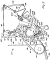
- FIG. 2 shows an envelope supply device 70 which to the lower rear area of the bale unloading gate 20 is connected to bale 58 which in the Bale formation chamber 56 are formed before being deposited on the Wrapping the bottom.
- the Envelope feeder 70 is configured to be a Envelope medium web, in particular a network web, whose Width is larger than that of the bale forming chamber 56 to in such a way not described in detail in the Bale forming chamber 56 to be introduced that the Wrapping agent web wrapped over the end edges of bale 58 becomes, as shown at point 71 in Figure 1.
- Wrapping material can be mesh, film or the like.
- each includes the envelope supply device 70 one Support frame attached to the rear lower half of the Bale discharge gate 20 is mounted and a vertical includes transverse wall 72 that extends transversely between extends vertical flanges and is attached to this, the rear ends of the opposing side walls 22 form the bale outlet gate 20.
- the wall 72 has one top end that of a down and back extending flange not shown is formed.
- Across extending legs of a pair of holders 76 for carrying Levers and formed as an angle are on upper right and left areas of wall 72 below the flange screwed on.
- a pair of brackets also designed as an angle 78 for clamping arms is vertically below the Pairs of holders 76 are provided and they have transverse ones Legs that are screwed to the wall 72.
- the main one Construction of the envelope supply device 70 further includes one A pair of longitudinally extending vertical support walls 80, the from viewed from the side roughly a triangular shape occupy, and front vertical sides that cross trending flanges are defined, the lower part overlap the wall 72 and attach to the structure at the end of the Bale unloading gate 20 z.
- Upper and lower shell supply rollers 82, 84 extend between the support walls 80 and with their ends in of these supported bearings rotatably, the Axis of rotation of the envelope feed roller 82 above and to the rear which is the envelope feed roller 84 so that a flat Envelope trajectory F at the gap between and tangential the envelope feed rollers 82, 84 and extends from the Gap extends upward and forward and under the wall 72.
- the upper envelope feed roller 82 is preferably made of one Metal core formed with a rubber or the like high friction is provided.
- the envelope feed roller 82 is arranged so that they are against the lower Envelope feed roller 84 is biased so that the latter is driven due to a frictional engagement with the first.
- a U-shaped and transversely extending holder 92 welded to the outer surface of each of the walls 80 attached.
- a pair of screws 102 extend each by the pair of outward facing end regions the shaft holder 98 and through the adjacent holder 92, and each screw 102 is by means of a nut 104 which in its threaded upper end is included in held in a set position.
- a coil spring 106 is located on each screw 102 and between each mutually associated holder 92 and shaft holder 98 clamped.
- a roll holder pin 110 which serves the Envelope feed roller 82 in one of shaft holder 98 to hold worn bearing extends through a circular opening, not shown, with play in the adjacent support wall 80, with the respective slots in a movement of the Envelope feed roller 82 to the lower envelope feed roller 84 there and back is allowed.
- the speed change gear 112 includes a washer 114 with a double groove on a shaft which is mounted as an extension of the lower rear roller 38 is attached, so that always a direct but optionally changeable relationship between the Belt 42 speed and peripheral speed the envelope feed rollers 82 and 84.
- a pair of straps 116 with a wedge-shaped profile is with the disc 114 and a variator disc 118, the latter connected to a left-hand extension of the support shaft of the upper one Envelope feed roller 82 is connected.
- the variator disc 118 is of a known type, the can be disassembled so that disks are added or removed can be adjusted to the width of the grooves that the belt 116th to be able to record.
- the addition of slices causes larger grooves with the consequence that the belts 116 run on a smaller diameter while doing the Increase speed while removing disks
- the consequence of narrowing the grooves is that the Belt 116 run on a larger diameter while doing so increase the speed.
- a tension pulley 120 is in one described below mounted so that they are optional brought into engagement with the lower strands of the belt 116 can be used to tension this and so a drive connection between disc 114 and variator disc 118 if it is desired that envelope 124 be incorporated into the Bale formation chamber 56 is fed to a bale 58 tie.
- An operational envelope roll 122 for dispensing Envelope 124 is shown in a position in which it is in Contact with the driven upper envelope feed roller 82 located.
- a strip of envelope 124 extends from a lower front position of the envelope roll 122 over the rear half of the upper envelope feed roller 82 and then through the gap between the shell supply rollers 82, 84.
- wrapping a bale 58 in the Bale formation chamber 56 runs the path of the wrapper 124 from the envelope feed rollers 82, 84 and comes in Attachment with part of an upper front quadrant to the lower envelope feed roller 84 and extends into the Gap 86 formed by straps 42 and section 88 of the Envelope guide assembly 90 is formed.
- the figures show more in detail below 2 or 3, the envelope 124, as it would be after it a location between the shell supply rollers 82 and 84 and the gap 86 separated or cut and the winding process has been started.
- a push arm assembly 126 is provided to approximate one to apply constant force to the sheave roll 122 to press it against the upper envelope feed roller 82 to a desired frictional resistance to the force to build that during the wrapping of the bale 58 tends to pull the sheath 124.
- the press arm assembly 126 includes separate lower and upper arm sections, one of which only lower arm section 128 shown and in detail is described.
- the lower arm portion 128 includes a pair Arm areas 132 that are spaced in the transverse direction to each other and the first end regions to one transverse rod 134 are welded, the Arm areas 132 for a vertical pivoting movement by one horizontal, transverse pivot axis are mounted, the is defined by respective bolts 136 that the opposite ends of the rod 134 to corresponding holders Connect 138 to the rear sides of the bulkheads 80 are attached.
- the arm portions 132 are made of molded Stripes or narrow plates are formed that are slight are curved or curved so that they are concave upwards, to take on a new role of envelope 124 when the lower arm section 128 in its lowered, down backward loading position is in which it is from a pair of flexible support members 140, here in the form of cables or ropes is held.
- a sleeve 142 is welded on 132.
- a pressure roller 144 extends between the sleeves 142 and is by means of corresponding bearing assemblies with screws 146 rotatable in held this.
- the pressure roller 144 engages at one point the circumference of the envelope roll 122, which is approximately diametrically opposite the contact area of the enveloping roll 122 with the upper envelope feed roller 82.
- a l- shaped power transmission plate 148 is on each arm portion 132 welded to form an extension of this, whereby the long leg of the "L" approximately with its central area is welded to the sleeve 142 and the short leg of the "L” is welded to arm portion 132 at its end.
- a bolt 150 is welded across each arm area 132, namely at the connection area of the short leg of the Power transmission plate 148 with arm portion 132.
- an angular knife support holder 190 which a nearby vertical knife mounting surface 192 defined, which extends transversely between the support walls 80.
- a knife 194 with a beveled upper end, one Cutting edge or cutting edge 196 is attached to the Knife mounting surface 192 attached.
- a separator 198 is formed from a piece of angle steel and extends in parallel relation to the cutting edge 196 and forms one Part of a cutter arm assembly, optionally from one Waiting position in which he over the cutting edge 196 in a position raised directly above the trajectory of the enveloping agent 124 is an unobstructed path at the beginning of the binding process to leave the strands 85 of the straps 42 in one Cutting position is moved in which one of the legs of the Winkelstahls touches the beveled surface that leads to the Cutting edge 196 guides, as shown in FIG. 2. in the Some of the cutting arm assemblies contain right and left extending a transverse distance from each other having arms 200 and 202, the front ends of which by Separating element 198 are connected to one another.
- the arms 200 and 202 are at their rear ends by means of a pivot shaft 204 connected to each other for pivoting in a pair cylindrical sleeves is included, each part of a Form pairs of mounting structures 208, each on the rear sides of the support walls 80 are attached.
- a pivot shaft 204 connected to each other for pivoting in a pair cylindrical sleeves is included, each part of a Form pairs of mounting structures 208, each on the rear sides of the support walls 80 are attached.
- an electrically driven reversible linear motor 210 to the right side wall 22 of the Bale discharge gate 20 is mounted and has an output shaft on, which is connected to a lever arm 212, which in turn is attached to the outer end of the pivot shaft 204.
- the Output shaft of motor 210 is in one extended state when the separating element 198 is in its raised waiting position.
- a clean and efficient cut of the wrapper 124 is achieved in that the bale 58th continues to rotate so that the sheath 124 is tensioned, while at the same time driving the envelope feed roller 82 turns off and this is braked, braking as follows the downward movement of the arm assembly 200, 202, 204 takes place. Specifically, is on the back An adjustable stop is attached to the area of the arm 202.
- the Tensioner roller 120 is attached to the end portion of a tensioner arm 250 worn, which is pivotable to the arm by means of a pin 252 202 attached and by means of a torsion spring assembly 254 is biased upwards.
- a downward movement the arm assembly then results in the tension of the Belt 116 is eliminated while the adjustable stop 240 brought into engagement with a brake pad, not shown is to manually attach the brake pad to its construction operable arm not shown in a brake engagement with the Swing belt 116.
- the separation device at least the knife 194 and that Separating element 198 with the respective holding and Actuating means.
- the brush 214 makes up with the bristles 216 in this embodiment, the holding device and at the same time represents the stripping device.
- the brush 214 fulfills two functions.
- One function is as one To act as a scraper, which prevents that at the beginning of the Wrapping cycle of the wrapper 124 around the Envelope feed roller 84 is wound, and the other Function is the free end of the tail of the web of the enveloping agent 124, if this is under the action of the anvil 198, which works against the knife 194, on one Place between the envelope feed rollers 82, 84 and the nip 86 is cut off.
- the purpose of inclusion or the Entanglement with the enveloping agent 124 is that this at the beginning of the next wrapping cycle on itself is folded back, as shown at 218 in Figure 3, which results in a double layer of envelope 124 the leading edge extending from the runs 85 to the gap 86 is promoted free of loose threads, whereupon the detached end is pulled out.
- This double layer of Envelope 124 at the leading edge of Envelope 124 engages a rear set not shown Spreading roller sections at the opposite ends of the Roller 38 which is arranged near the gap 86.
- the double layer of the envelope 124 to reinforcement of the rear spreading roller sections and with a front set of spreader roller sections not shown at the opposite end regions of the roller 40 leads to a spreading or maintaining the envelope width, so that proper wrapping of the bale 58 occurs.
- the web has enveloping means 124 due to the envelope the leading end of the path of the envelope 124, which of hanging fibers freed, a lower inclination around Spreaders to be wound on the rollers.
- the Structure of the spreading rollers is in the US patent application with the Serial number 09 / 008,515 shown, and this can refer to be taken if details of the spreader roller are desired become.
- the present invention is not for use with a press 10 limited, in the enveloping means 124 in one Width is supplied, which is the width of the baling chamber 56th exceeds; rather, the present invention can also a conventional press 10 with fixed or variable Bale press room and an envelope width can be used essentially corresponds to the bale width.
Landscapes
- Life Sciences & Earth Sciences (AREA)
- Environmental Sciences (AREA)
- Basic Packing Technique (AREA)
- Braiding, Manufacturing Of Bobbin-Net Or Lace, And Manufacturing Of Nets By Knotting (AREA)
- Feed For Specific Animals (AREA)
- Magnetic Resonance Imaging Apparatus (AREA)
Applications Claiming Priority (4)
| Application Number | Priority Date | Filing Date | Title |
|---|---|---|---|
| US439935 | 1982-11-08 | ||
| US09/439,935 US6272816B1 (en) | 1999-11-12 | 1999-11-12 | Large wrapping net roll pressure arm assembly serving also as a loading platform |
| US452072 | 1999-11-30 | ||
| US09/452,072 US6622463B1 (en) | 1999-11-30 | 1999-11-30 | Device for folding leading end of net-type bale wrapping material to enhance its full-width conveyance into the baling chamber |
Publications (2)
| Publication Number | Publication Date |
|---|---|
| EP1099367A1 true EP1099367A1 (fr) | 2001-05-16 |
| EP1099367B1 EP1099367B1 (fr) | 2005-03-16 |
Family
ID=27032226
Family Applications (1)
| Application Number | Title | Priority Date | Filing Date |
|---|---|---|---|
| EP00123785A Expired - Lifetime EP1099367B1 (fr) | 1999-11-12 | 2000-11-02 | Dispositif d'alimentation de gaine pour enrubannage |
Country Status (3)
| Country | Link |
|---|---|
| EP (1) | EP1099367B1 (fr) |
| AT (1) | ATE290769T1 (fr) |
| DE (1) | DE50009772D1 (fr) |
Cited By (4)
| Publication number | Priority date | Publication date | Assignee | Title |
|---|---|---|---|---|
| CN109937716A (zh) * | 2019-04-12 | 2019-06-28 | 黑龙江省福丰机械制造有限公司 | 一种新型圆包机结构 |
| EP3539369A1 (fr) * | 2018-03-15 | 2019-09-18 | Deere & Company | Système d'emballage de matériau comportant un élément de nettoyage |
| US10820527B2 (en) | 2018-07-13 | 2020-11-03 | Deere & Company | Baler with netwrap roll loading device |
| US10934143B2 (en) | 2018-07-13 | 2021-03-02 | Deere & Company | Net wrap lifting device |
Citations (5)
| Publication number | Priority date | Publication date | Assignee | Title |
|---|---|---|---|---|
| US4787193A (en) | 1986-07-08 | 1988-11-29 | Deere & Company | System for automatically enveloping a large round bale with a wrapping |
| US5216873A (en) * | 1991-10-07 | 1993-06-08 | Hay & Forage Industries | Wrapper cutoff mechanism for round balers |
| EP0807380A1 (fr) * | 1996-05-14 | 1997-11-19 | New Holland Belgium N.V. | Presse à balles rondes avec dispositif enveloppeur |
| EP0931449A1 (fr) * | 1998-01-16 | 1999-07-28 | Deere & Company | Presse avec dispositif d'enveloppage |
| US6050052A (en) * | 1998-06-17 | 2000-04-18 | Hay & Forage Industries | Round baler having positive start wrapper dispensing mechanism |
-
2000
- 2000-11-02 EP EP00123785A patent/EP1099367B1/fr not_active Expired - Lifetime
- 2000-11-02 DE DE50009772T patent/DE50009772D1/de not_active Expired - Lifetime
- 2000-11-02 AT AT00123785T patent/ATE290769T1/de not_active IP Right Cessation
Patent Citations (5)
| Publication number | Priority date | Publication date | Assignee | Title |
|---|---|---|---|---|
| US4787193A (en) | 1986-07-08 | 1988-11-29 | Deere & Company | System for automatically enveloping a large round bale with a wrapping |
| US5216873A (en) * | 1991-10-07 | 1993-06-08 | Hay & Forage Industries | Wrapper cutoff mechanism for round balers |
| EP0807380A1 (fr) * | 1996-05-14 | 1997-11-19 | New Holland Belgium N.V. | Presse à balles rondes avec dispositif enveloppeur |
| EP0931449A1 (fr) * | 1998-01-16 | 1999-07-28 | Deere & Company | Presse avec dispositif d'enveloppage |
| US6050052A (en) * | 1998-06-17 | 2000-04-18 | Hay & Forage Industries | Round baler having positive start wrapper dispensing mechanism |
Cited By (6)
| Publication number | Priority date | Publication date | Assignee | Title |
|---|---|---|---|---|
| EP3539369A1 (fr) * | 2018-03-15 | 2019-09-18 | Deere & Company | Système d'emballage de matériau comportant un élément de nettoyage |
| US10888048B2 (en) | 2018-03-15 | 2021-01-12 | Deere & Company | Material wrap system with self cleaning feature |
| US10820527B2 (en) | 2018-07-13 | 2020-11-03 | Deere & Company | Baler with netwrap roll loading device |
| US10934143B2 (en) | 2018-07-13 | 2021-03-02 | Deere & Company | Net wrap lifting device |
| US11299379B2 (en) | 2018-07-13 | 2022-04-12 | Deere & Company | Net wrap lifting device |
| CN109937716A (zh) * | 2019-04-12 | 2019-06-28 | 黑龙江省福丰机械制造有限公司 | 一种新型圆包机结构 |
Also Published As
| Publication number | Publication date |
|---|---|
| EP1099367B1 (fr) | 2005-03-16 |
| DE50009772D1 (de) | 2005-04-21 |
| ATE290769T1 (de) | 2005-04-15 |
Similar Documents
| Publication | Publication Date | Title |
|---|---|---|
| DE69711751T2 (de) | Rundballenpresse mit Einwickelvorrichtung | |
| EP0931449B1 (fr) | Presse avec dispositif d'enveloppage | |
| DE2851035C2 (de) | Erntegut-Rundballenformmaschine | |
| EP1099366B1 (fr) | Dispositif d'alimentation de gaine pour enrubannage | |
| DE2443838C3 (de) | Aufsammel-Rollballenpresse | |
| DE69909188T2 (de) | Umhüllungsvorrichtung für Rundballen | |
| DE3879999T2 (de) | Foerderrollen fuer netzgewebespender in rundballenpressen. | |
| DE10063122A1 (de) | Rundballenpresse | |
| WO2000064237A1 (fr) | Procede pour envelopper une balle ronde pressee dans une presse a balles rondes, dispositif d'enveloppement avec film et presse a balles rondes pourvue d'un tel dispositif | |
| DE3443666A1 (de) | Ballenpresse | |
| EP0157898A1 (fr) | Mécanisme de liage pour presses à balles rondes | |
| DE2826904C2 (fr) | ||
| DE2448645A1 (de) | Heurollen-formmaschine | |
| DE3443530A1 (de) | Ballenpresse | |
| EP1064839A1 (fr) | Dispositif pour fixer un bout de fil libre sur une balle ronde | |
| DE2538164C3 (de) | Rundballenpresse für Heu und anderes faseriges Erntegut mit einer Spannvorrichtung für die den Balten formenden umlaufbaren Bänder | |
| DE3501062A1 (de) | Ballenpresse | |
| DE2947442C2 (fr) | ||
| DE69521457T2 (de) | Ballen-Lade-Wagen um Ballen an eine Wickelvorrichtung abzugeben | |
| DE2530320C3 (de) | Bindevorrichtung für Wickelballenpressen | |
| EP0535532A2 (fr) | Procédé et dispositif pour lier des balles de récolte | |
| EP0095689B1 (fr) | Presse à balles rondes dont la chambre de compactage comprend une entrée pour le matériau | |
| DE3734186A1 (de) | Aufsammel-rollballenpresse | |
| DE69613526T2 (de) | Maschine und Verfahren um Rundballen zu Umhüllen | |
| EP1099367B1 (fr) | Dispositif d'alimentation de gaine pour enrubannage |
Legal Events
| Date | Code | Title | Description |
|---|---|---|---|
| PUAI | Public reference made under article 153(3) epc to a published international application that has entered the european phase |
Free format text: ORIGINAL CODE: 0009012 |
|
| AK | Designated contracting states |
Kind code of ref document: A1 Designated state(s): AT BE CH CY DE DK ES FI FR GB GR IE IT LI LU MC NL PT SE TR |
|
| AX | Request for extension of the european patent |
Free format text: AL;LT;LV;MK;RO;SI |
|
| 17P | Request for examination filed |
Effective date: 20011116 |
|
| AKX | Designation fees paid |
Free format text: AT BE CH CY DE DK ES FI FR GB GR IE IT LI LU MC NL PT SE TR |
|
| 17Q | First examination report despatched |
Effective date: 20040325 |
|
| GRAP | Despatch of communication of intention to grant a patent |
Free format text: ORIGINAL CODE: EPIDOSNIGR1 |
|
| GRAS | Grant fee paid |
Free format text: ORIGINAL CODE: EPIDOSNIGR3 |
|
| GRAA | (expected) grant |
Free format text: ORIGINAL CODE: 0009210 |
|
| AK | Designated contracting states |
Kind code of ref document: B1 Designated state(s): AT BE CH CY DE DK ES FI FR GB GR IE IT LI LU MC NL PT SE TR |
|
| PG25 | Lapsed in a contracting state [announced via postgrant information from national office to epo] |
Ref country code: TR Free format text: LAPSE BECAUSE OF FAILURE TO SUBMIT A TRANSLATION OF THE DESCRIPTION OR TO PAY THE FEE WITHIN THE PRESCRIBED TIME-LIMIT Effective date: 20050316 Ref country code: FI Free format text: LAPSE BECAUSE OF FAILURE TO SUBMIT A TRANSLATION OF THE DESCRIPTION OR TO PAY THE FEE WITHIN THE PRESCRIBED TIME-LIMIT Effective date: 20050316 |
|
| REG | Reference to a national code |
Ref country code: GB Ref legal event code: FG4D Free format text: NOT ENGLISH |
|
| REG | Reference to a national code |
Ref country code: CH Ref legal event code: EP |
|
| REG | Reference to a national code |
Ref country code: IE Ref legal event code: FG4D Free format text: GERMAN |
|
| REF | Corresponds to: |
Ref document number: 50009772 Country of ref document: DE Date of ref document: 20050421 Kind code of ref document: P |
|
| GBT | Gb: translation of ep patent filed (gb section 77(6)(a)/1977) |
Effective date: 20050427 |
|
| PG25 | Lapsed in a contracting state [announced via postgrant information from national office to epo] |
Ref country code: DK Free format text: LAPSE BECAUSE OF FAILURE TO SUBMIT A TRANSLATION OF THE DESCRIPTION OR TO PAY THE FEE WITHIN THE PRESCRIBED TIME-LIMIT Effective date: 20050616 Ref country code: GR Free format text: LAPSE BECAUSE OF FAILURE TO SUBMIT A TRANSLATION OF THE DESCRIPTION OR TO PAY THE FEE WITHIN THE PRESCRIBED TIME-LIMIT Effective date: 20050616 |
|
| PG25 | Lapsed in a contracting state [announced via postgrant information from national office to epo] |
Ref country code: ES Free format text: LAPSE BECAUSE OF FAILURE TO SUBMIT A TRANSLATION OF THE DESCRIPTION OR TO PAY THE FEE WITHIN THE PRESCRIBED TIME-LIMIT Effective date: 20050627 |
|
| PG25 | Lapsed in a contracting state [announced via postgrant information from national office to epo] |
Ref country code: PT Free format text: LAPSE BECAUSE OF FAILURE TO SUBMIT A TRANSLATION OF THE DESCRIPTION OR TO PAY THE FEE WITHIN THE PRESCRIBED TIME-LIMIT Effective date: 20050907 |
|
| PG25 | Lapsed in a contracting state [announced via postgrant information from national office to epo] |
Ref country code: CY Free format text: LAPSE BECAUSE OF FAILURE TO SUBMIT A TRANSLATION OF THE DESCRIPTION OR TO PAY THE FEE WITHIN THE PRESCRIBED TIME-LIMIT Effective date: 20051102 Ref country code: AT Free format text: LAPSE BECAUSE OF NON-PAYMENT OF DUE FEES Effective date: 20051102 |
|
| PG25 | Lapsed in a contracting state [announced via postgrant information from national office to epo] |
Ref country code: LI Free format text: LAPSE BECAUSE OF NON-PAYMENT OF DUE FEES Effective date: 20051130 Ref country code: CH Free format text: LAPSE BECAUSE OF NON-PAYMENT OF DUE FEES Effective date: 20051130 Ref country code: MC Free format text: LAPSE BECAUSE OF NON-PAYMENT OF DUE FEES Effective date: 20051130 Ref country code: LU Free format text: LAPSE BECAUSE OF NON-PAYMENT OF DUE FEES Effective date: 20051130 |
|
| PLBE | No opposition filed within time limit |
Free format text: ORIGINAL CODE: 0009261 |
|
| STAA | Information on the status of an ep patent application or granted ep patent |
Free format text: STATUS: NO OPPOSITION FILED WITHIN TIME LIMIT |
|
| ET | Fr: translation filed | ||
| 26N | No opposition filed |
Effective date: 20051219 |
|
| REG | Reference to a national code |
Ref country code: CH Ref legal event code: PL |
|
| PG25 | Lapsed in a contracting state [announced via postgrant information from national office to epo] |
Ref country code: SE Free format text: LAPSE BECAUSE OF FAILURE TO SUBMIT A TRANSLATION OF THE DESCRIPTION OR TO PAY THE FEE WITHIN THE PRESCRIBED TIME-LIMIT Effective date: 20050616 |
|
| PGFP | Annual fee paid to national office [announced via postgrant information from national office to epo] |
Ref country code: NL Payment date: 20081124 Year of fee payment: 9 |
|
| PGFP | Annual fee paid to national office [announced via postgrant information from national office to epo] |
Ref country code: BE Payment date: 20090128 Year of fee payment: 9 |
|
| PGFP | Annual fee paid to national office [announced via postgrant information from national office to epo] |
Ref country code: IE Payment date: 20091124 Year of fee payment: 10 |
|
| BERE | Be: lapsed |
Owner name: *DEERE & CY Effective date: 20091130 |
|
| REG | Reference to a national code |
Ref country code: NL Ref legal event code: V1 Effective date: 20100601 |
|
| PG25 | Lapsed in a contracting state [announced via postgrant information from national office to epo] |
Ref country code: NL Free format text: LAPSE BECAUSE OF NON-PAYMENT OF DUE FEES Effective date: 20100601 Ref country code: BE Free format text: LAPSE BECAUSE OF NON-PAYMENT OF DUE FEES Effective date: 20091130 |
|
| REG | Reference to a national code |
Ref country code: IE Ref legal event code: MM4A |
|
| PG25 | Lapsed in a contracting state [announced via postgrant information from national office to epo] |
Ref country code: IE Free format text: LAPSE BECAUSE OF NON-PAYMENT OF DUE FEES Effective date: 20101102 |
|
| REG | Reference to a national code |
Ref country code: FR Ref legal event code: PLFP Year of fee payment: 16 |
|
| PGFP | Annual fee paid to national office [announced via postgrant information from national office to epo] |
Ref country code: DE Payment date: 20151127 Year of fee payment: 16 Ref country code: IT Payment date: 20151124 Year of fee payment: 16 Ref country code: GB Payment date: 20151127 Year of fee payment: 16 |
|
| PGFP | Annual fee paid to national office [announced via postgrant information from national office to epo] |
Ref country code: FR Payment date: 20151117 Year of fee payment: 16 |
|
| REG | Reference to a national code |
Ref country code: DE Ref legal event code: R119 Ref document number: 50009772 Country of ref document: DE |
|
| GBPC | Gb: european patent ceased through non-payment of renewal fee |
Effective date: 20161102 |
|
| REG | Reference to a national code |
Ref country code: FR Ref legal event code: ST Effective date: 20170731 |
|
| PG25 | Lapsed in a contracting state [announced via postgrant information from national office to epo] |
Ref country code: FR Free format text: LAPSE BECAUSE OF NON-PAYMENT OF DUE FEES Effective date: 20161130 Ref country code: IT Free format text: LAPSE BECAUSE OF NON-PAYMENT OF DUE FEES Effective date: 20161102 |
|
| PG25 | Lapsed in a contracting state [announced via postgrant information from national office to epo] |
Ref country code: DE Free format text: LAPSE BECAUSE OF NON-PAYMENT OF DUE FEES Effective date: 20170601 Ref country code: GB Free format text: LAPSE BECAUSE OF NON-PAYMENT OF DUE FEES Effective date: 20161102 |