EP0931493A1 - Whipping tool for a kitchen robot - Google Patents
Whipping tool for a kitchen robot Download PDFInfo
- Publication number
- EP0931493A1 EP0931493A1 EP99400096A EP99400096A EP0931493A1 EP 0931493 A1 EP0931493 A1 EP 0931493A1 EP 99400096 A EP99400096 A EP 99400096A EP 99400096 A EP99400096 A EP 99400096A EP 0931493 A1 EP0931493 A1 EP 0931493A1
- Authority
- EP
- European Patent Office
- Prior art keywords
- whip
- branch
- arm
- tank
- around
- Prior art date
- Legal status (The legal status is an assumption and is not a legal conclusion. Google has not performed a legal analysis and makes no representation as to the accuracy of the status listed.)
- Ceased
Links
- 239000011295 pitch Substances 0.000 claims abstract 2
- 238000002360 preparation method Methods 0.000 claims description 22
- 239000003638 chemical reducing agent Substances 0.000 claims description 8
- 229920003023 plastic Polymers 0.000 claims description 8
- 239000002184 metal Substances 0.000 claims description 6
- 230000003247 decreasing effect Effects 0.000 claims description 2
- 235000013305 food Nutrition 0.000 abstract description 12
- 235000014103 egg white Nutrition 0.000 description 6
- 210000000969 egg white Anatomy 0.000 description 6
- 239000000839 emulsion Substances 0.000 description 5
- 239000000463 material Substances 0.000 description 5
- 239000007788 liquid Substances 0.000 description 4
- 230000005484 gravity Effects 0.000 description 3
- 239000000203 mixture Substances 0.000 description 3
- 230000001681 protective effect Effects 0.000 description 3
- 239000006071 cream Substances 0.000 description 2
- 235000013601 eggs Nutrition 0.000 description 2
- 210000000056 organ Anatomy 0.000 description 2
- 239000008256 whipped cream Substances 0.000 description 2
- 230000001154 acute effect Effects 0.000 description 1
- 238000004026 adhesive bonding Methods 0.000 description 1
- 230000003416 augmentation Effects 0.000 description 1
- 238000005119 centrifugation Methods 0.000 description 1
- 210000000078 claw Anatomy 0.000 description 1
- 230000009194 climbing Effects 0.000 description 1
- 230000007423 decrease Effects 0.000 description 1
- 239000010432 diamond Substances 0.000 description 1
- 238000006073 displacement reaction Methods 0.000 description 1
- 235000013345 egg yolk Nutrition 0.000 description 1
- 210000002969 egg yolk Anatomy 0.000 description 1
- 239000007937 lozenge Substances 0.000 description 1
- 238000004519 manufacturing process Methods 0.000 description 1
- 239000008268 mayonnaise Substances 0.000 description 1
- 235000010746 mayonnaise Nutrition 0.000 description 1
- 238000000465 moulding Methods 0.000 description 1
- 230000035515 penetration Effects 0.000 description 1
- 230000000284 resting effect Effects 0.000 description 1
- 229910001220 stainless steel Inorganic materials 0.000 description 1
Images



Classifications
-
- A—HUMAN NECESSITIES
- A47—FURNITURE; DOMESTIC ARTICLES OR APPLIANCES; COFFEE MILLS; SPICE MILLS; SUCTION CLEANERS IN GENERAL
- A47J—KITCHEN EQUIPMENT; COFFEE MILLS; SPICE MILLS; APPARATUS FOR MAKING BEVERAGES
- A47J43/00—Implements for preparing or holding food, not provided for in other groups of this subclass
- A47J43/04—Machines for domestic use not covered elsewhere, e.g. for grinding, mixing, stirring, kneading, emulsifying, whipping or beating foodstuffs, e.g. power-driven
- A47J43/07—Parts or details, e.g. mixing tools, whipping tools
- A47J43/0716—Parts or details, e.g. mixing tools, whipping tools for machines with tools driven from the lower side
- A47J43/0722—Mixing, whipping or cutting tools
-
- B—PERFORMING OPERATIONS; TRANSPORTING
- B01—PHYSICAL OR CHEMICAL PROCESSES OR APPARATUS IN GENERAL
- B01F—MIXING, e.g. DISSOLVING, EMULSIFYING OR DISPERSING
- B01F27/00—Mixers with rotary stirring devices in fixed receptacles; Kneaders
- B01F27/05—Stirrers
- B01F27/11—Stirrers characterised by the configuration of the stirrers
- B01F27/114—Helically shaped stirrers, i.e. stirrers comprising a helically shaped band or helically shaped band sections
- B01F27/1142—Helically shaped stirrers, i.e. stirrers comprising a helically shaped band or helically shaped band sections of the corkscrew type
-
- B—PERFORMING OPERATIONS; TRANSPORTING
- B01—PHYSICAL OR CHEMICAL PROCESSES OR APPARATUS IN GENERAL
- B01F—MIXING, e.g. DISSOLVING, EMULSIFYING OR DISPERSING
- B01F27/00—Mixers with rotary stirring devices in fixed receptacles; Kneaders
- B01F27/80—Mixers with rotary stirring devices in fixed receptacles; Kneaders with stirrers rotating about a substantially vertical axis
- B01F27/95—Mixers with rotary stirring devices in fixed receptacles; Kneaders with stirrers rotating about a substantially vertical axis with stirrers having planetary motion, i.e. rotating about their own axis and about a sun axis
-
- B—PERFORMING OPERATIONS; TRANSPORTING
- B01—PHYSICAL OR CHEMICAL PROCESSES OR APPARATUS IN GENERAL
- B01F—MIXING, e.g. DISSOLVING, EMULSIFYING OR DISPERSING
- B01F27/00—Mixers with rotary stirring devices in fixed receptacles; Kneaders
- B01F27/80—Mixers with rotary stirring devices in fixed receptacles; Kneaders with stirrers rotating about a substantially vertical axis
- B01F27/96—Mixers with rotary stirring devices in fixed receptacles; Kneaders with stirrers rotating about a substantially vertical axis with openwork frames or cages
-
- B—PERFORMING OPERATIONS; TRANSPORTING
- B01—PHYSICAL OR CHEMICAL PROCESSES OR APPARATUS IN GENERAL
- B01F—MIXING, e.g. DISSOLVING, EMULSIFYING OR DISPERSING
- B01F27/00—Mixers with rotary stirring devices in fixed receptacles; Kneaders
- B01F27/05—Stirrers
- B01F27/11—Stirrers characterised by the configuration of the stirrers
- B01F27/13—Openwork frame or cage stirrers not provided for in other groups of this subclass
-
- B—PERFORMING OPERATIONS; TRANSPORTING
- B01—PHYSICAL OR CHEMICAL PROCESSES OR APPARATUS IN GENERAL
- B01F—MIXING, e.g. DISSOLVING, EMULSIFYING OR DISPERSING
- B01F27/00—Mixers with rotary stirring devices in fixed receptacles; Kneaders
- B01F27/23—Mixers with rotary stirring devices in fixed receptacles; Kneaders characterised by the orientation or disposition of the rotor axis
- B01F27/232—Mixers with rotary stirring devices in fixed receptacles; Kneaders characterised by the orientation or disposition of the rotor axis with two or more rotation axes
- B01F27/2321—Mixers with rotary stirring devices in fixed receptacles; Kneaders characterised by the orientation or disposition of the rotor axis with two or more rotation axes having different inclinations, e.g. non parallel
-
- B—PERFORMING OPERATIONS; TRANSPORTING
- B01—PHYSICAL OR CHEMICAL PROCESSES OR APPARATUS IN GENERAL
- B01F—MIXING, e.g. DISSOLVING, EMULSIFYING OR DISPERSING
- B01F27/00—Mixers with rotary stirring devices in fixed receptacles; Kneaders
- B01F27/23—Mixers with rotary stirring devices in fixed receptacles; Kneaders characterised by the orientation or disposition of the rotor axis
- B01F27/232—Mixers with rotary stirring devices in fixed receptacles; Kneaders characterised by the orientation or disposition of the rotor axis with two or more rotation axes
- B01F27/2324—Mixers with rotary stirring devices in fixed receptacles; Kneaders characterised by the orientation or disposition of the rotor axis with two or more rotation axes planetary
Definitions
- the present invention relates to a device for whisk rotated in a bowl of a food preparation appliance.
- This device whisk is specially designed for whipping whites egg in snow, or to beat other emulsions such as a mixture of egg yolks and oil emulsified together to make mayonnaise, or even to prepare a whipped cream or a whipped cream from fresh cream or whipping cream.
- the device whip is rotated by the motor shaft the device at a relatively low speed constant between 500 and 700 rpm.
- the constant speed of rotation can be selected in increments of a few tens of revolutions / min.
- some whip devices incorporate a reducer gear meshing with one end of the shaft engine.
- the whip device can include two diametrically opposite whips that rotate in solidarity with the motor shaft.
- each whip shaped like a flat plastic contained in a plane radial to the motor shaft and having relatively wide flat wings, perforated by vertical and horizontal slits.
- One of wings of the vee is free and grazes the internal wall of the tank of the apparatus, and the other wing of the vee is secured to a cap mounted on one end of the drive shaft.
- Two such wide-wing vee whips planes are monolithic with the cap to be manufactured in a single molded material plastic.
- the whisk is made up of several wires metallic developed substantially according to generating a truncated cone and linked to a washer crossed by a central spindle and located at the large base of the truncated cone.
- the pin is snapped into an eccentric sheath of a plate rotating with the motor shaft of the device, so that the pin describes a circle around the axis of the device shaft and simultaneously the whip turns on itself by means of a reduction gear between the axis of the whip and the motor shaft.
- the rotation whip on itself is created by means mechanical rotational drive between the shaft motor and a support, cap or pin, of the whisk.
- the rotation of the whisk begins with the start of the device at a constant speed directly proportional to the shaft rotation speed engine.
- the sudden passage of the state whip stationary in the rotating state at a relatively speed high is not conducive to a suitable climb of egg whites or any emulsion whip or beat. Indeed, at the start of the rotation of the motor shaft and the whip device with the rotation of the whip (s) on themselves, a part of the egg whites is centrifuged against the internal surface of the tank wall.
- French patent application FR-2 282 932 and the German patent DE-402 411 discloses an apparatus mixer comprising a rotating agitating member freely around an arm inclined at 45 ° or perpendicular to a drive shaft located at center of a tank.
- the agitating member can move on the arm in front of a stop at the free end of the arm and consists of an axial circular plate on the arm and on which rods of different lengths are arranged.
- the arm around which the agitator rotates is located near the upper part of the tank and has a double isosceles trapezoid shape so that the material to be mixed is mostly brewed at the level of the walls of the tank.
- the aforementioned known agitating bodies are not not well suited to beat sparse emulsions such as egg whites.
- the agitating organ according to demand FR-2 282 932 is heavy and tends to go up along the arm.
- the agitating organ according to patent DE-402 411 revolves around an axis perpendicular to the motor rotation axis and located above the mixture and is subjected so discontinuous to the resistance of the mixture and therefore imbalance.
- the objective of the invention is to provide a whip device for preparation apparatus culinary in which sparse emulsions, such as egg whites or the like are whipped or beaten with at least one rotating whip freely at first slow rotation speed then progressively higher and higher, from starting the rotation of the motor shaft the appliance, without the whip vibrating.
- a whip device for a food preparation appliance which includes a rotary motor shaft, a tank having a bottom which, in axial half-section along the drive shaft, has a profile substantially symmetrical about an axis predetermined, an arm having a first branch rotated around the axis of the tank by the drive shaft and a second branch extending along said predetermined axis towards the bottom of the tank, and a whip mounted with free rotation around the second branch, is characterized in that the whip includes a first frustoconical helical portion focused around the second arm branch and having a small base mounted with free rotation around the second arm branch, the first portion helical having an apex angle substantially equal to the angle at the top of a bottom vee tank seen in axial section.
- the whip according to the invention can comprise a second frustoconical helical portion having a large common base with the first portion frustoconical helical and a small base mounted at free rotation around the second arm branch.
- the steps of the first and second tapered helical portions of the device can be identical, that is to say the step in the helical whip is constant, the first and second tapered helical portions of the device may have different steps for better balance the whip according to the invention.
- the first frustoconical helical portion of the device has a step increasing gradually from the small base mounted with free rotation of this one towards the large common base
- the second tapered helical portion has a decreasing pitch gradually from the large common base towards the small base mounted with free rotation thereof.
- the free rotation assembly, called crazy assembly, of the whip around the arm allows the whip to rotate very low speed compared to the motor shaft at the start of the start of the latter, and at a speed gradually higher and higher when the culinary preparation becomes more voluminous.
- the whisk thus has a first portion propeller with a profile similar to the profile substantially symmetrical to the bottom.
- Portions annulars at the ends of the whip are guided freely around the second arm branch and held between respective stops on the second arm branch so that the whip is kept in the tank.
- the stops are for example removable or integrated into the second branch by deformation.
- the whip is mounted at free rotation so as to keep the whisk at a constant height position in the tank for flush the bottom of the tank. So the whip has freely guided annular portions around the second arm branch and held between respective stops on the second branch of arms.
- the annular portions are circular loops at the end of a wire bent metal constituting said whip.
- the whip device has two whips mounted with free rotation around second branches of two arms symmetrical about the axis of the tank and driven together rotating around the axis of the tank by the motor shaft.
- the whip device includes a cylindrical whisk holder cap which is attached removably around the motor shaft and to which the first arm branch is attached.
- the arm can understand a third branch, preferably parallel to the axis of the tank, connected to the first branch and substantially embedded in the whip holder cap cylindrical so as to strengthen the bond metal / plastic between arms and cap.
- the whip-holder cap surrounds a skirt tank center without contact around the shaft engine to protect the unit's engine block at the motor shaft against penetration of food.
- the whip device includes a speed reducer having a fixed central pinion of removably around the motor shaft and a planetary gear meshing in the central gear, and a third arm branch connected by an elbow embedded in a cylindrical whip holder cap at the first arm branch.
- the planetary gear is rotatably mounted around the third leg.
- the whip holder cap is rotatably mounted removable around the motor shaft and supported by this and preferably surrounds a central skirt of the tank surrounding the motor shaft without contact.
- the whip device may further comprise a cap fixed under a cover of the tank, covering at least part of the whip holder cap in which the planetary gear is housed, and having an internal gear ring meshing with the planetary gear and surrounding the gear central.
- each arm is a rod angled metal and the whip holder cap is plastic material.
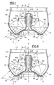
- a tank 1 in preferably transparent plastic for food preparation appliance has a axial symmetry about a vertical axis YY.
- the tank has a bottom 20-21 whose profile in axial section is in W shape, i.e. two symmetrical ves by relative to the YY axis, which have vertices 22 forming a circular base of the tank around the YY axis and which are connected by a central cylindrical skirt 23 prominent in the tank.
- the internal branches of ves of W connected to the base of skirt 23 are generating an internal frustoconical portion 20 of the bottom whose large base is formed by the foot circular 22 and whose small base supports the skirt cylindrical 23.
- the outer branches of the vee of the W are generators of a frustoconical portion external 21 of the bottom, the small base of which is formed by the circular base 22 and whose large base is nested and fixed by gluing to the large base bottom of a wall 10, cylindrical or substantially in a spherical cap 10 of the tank 1.
- the circular junction 11 between the large base of the external frustoconical portion 21 of the tank bottom and the tank wall 10 is at a level higher than the small base of the internal frustoconical portion 20 of the tank bottom supporting the skirt 23 relative to the foot 22 common to the frustoconical portions 20 and 21.
- AA axis is actually a generator a cone whose base is formed by the foot circular 22, which is centered on the axis of symmetry YY and which has a half angle at the vertex ⁇ included between 5 ° and 15 °, preferably about 10 °.
- the internal frustoconical portion 20 of the bottom of tank has a frustoconical cavity located under the tank having 24 legs to fix the tank around of a frustoconical protuberance 30 of a base 3 of the food preparation appliance, the base circular 22 of the tank resting on the base of the tank.
- the base 3 constitutes the engine block of the food preparation appliance.
- the upper end 32 of the shaft 31 included in the skirt 23 has a non-circular section, by hexagonal example, so as to fit into abutment in a sleeve 40 of an accessory holder 4, additional internal hexagonal section.
- the accessory holder 4 comprises a cylindrical protective cap 41 terminated by an upper shoulder 411 bonded by bonding or assembled in polygonal sections 412 at the periphery upper part of the sleeve 40.
- the protective sleeve 41 surrounds the major upper part of the skirt 23 of so as to avoid the ingress of food into this one.
- the accessory holder is a Whip holder 4.
- the whip holder includes, in addition to the sleeve 40 and cap 41, at least one bent arm 42 supporting a whip 7, or two arms 42 diametrically opposed each supporting a whip as shown in Figure 2.
- the arm 42 is a bent metal rod and has a first branch 421 which extends radially to the cap 41 and one end of which is embedded therein during the molding of the latter, the cap and the sleeve 40 being in plastic material.
- the other end of the branch 421 is connected by an obtuse elbow 423 to a second arm 422 of arm 42, longer than the first branch 421.
- the branch 422 extends along the axis AA, that is to say extends in an axial plane to the whip holder 4 and to tank 1 and is inclined at an angle acute ⁇ with respect to the axis of rotation YY of the whisk holder 4.
- the whisk holder includes two arms each supporting two whips, or three or four arms each supporting a whip, regularly distributed around the cap 41 and positioned in axial sections of the tank in a way similar to the arm of the whip 7 described below.
- two whips 7 are mounted respectively between stops 424 and 425 of two arms 42.
- the stops 424 and 425 are provided respectively at the free end of the second arm branch 422 under an annular portion of lower guide 74 of the whip 7 and close to the other end of the branch 422, under the elbow 423, and more precisely just above a annular upper guide portion 75 of the whisk 7.
- the stops 424 and 425 are claw washers engaged in adequate throats of branch 422, or deformations in the form of bulges substantially semi-toric on branch 422.
- the stops 424 and 425 prevent climbing or descending the whip along the second arm branch 422.
- the whip 7 is thus mounted with free rotation around branch 422 and immobile in translation with low clearance between stops 424 and 425.
- Each whip 7 is a stainless steel wire shaped like a frusto-conical double helix, low section, typically 2 mm.
- Whip 7 is shaped from a portion lower annular guide 74 formed by a O-ring abutting on bottom stop 424 up to an upper annular guide portion 75 formed by a second O-ring abutting under the upper stop 425, in a frustoconical propeller lower 72 then in a tapered helix upper 73.
- the annular guide portions 74 and 75 at the ends of the whip 7 are mounted at free rotation with a slight play around the second arm branch 422.
- the propellers are of same direction and have a large common base located substantially in a mediator plane at branch 422 between stops 424 and 425 which are located substantially at the vertices of propellers 72 and 73 respectively.
- Propellers 72 and 73 include each about one to three turns and have substantially identical lengths.
- each whisk 7 are such that the whip almost sweeps a volume at lozenge or square section VF, around the skirt of tank 23, between the frustoconical portions 20 and 21 of the bottom as shown in figure 1, when the whisk holder 4 integral in rotation with the motor shaft 31 rotates around the axis of symmetry YY of tank 1 and when the whip 7 is driven in free rotation around the axis AA of the second branch 422 of the arm 42.
- This free rotation is due to displacement whip resistant in liquid L when whip holder rotation.
- the lower propeller 72 and the annular portion 74 of the whip 7 are close to the portions respectively frustoconical from the bottom 20-21 and the base 22 a few millimeters, typically 3 to 5 mm.
- the whip 7 thus rotates in a volume in the form of circular V-shaped crown around the YY axis delimited substantially by half lower diamond or square VF centered on the axis AA, as shown in Figure 1.
- the angle at the top of the cone in which the propeller lower 72 turns on itself is substantially equal to the angle at the top of the circular vee formed by the frustoconical bottom portions 20 and 21.
- the height of the propeller 72 is substantially equal to that from bottom vee 20-21.
- each propeller 72, 73 has a large base diameter of approximately 70 mm, a height between 40 and 70 mm approximately, and a apex angle between about 45 ° and 60 °.
- the whip 7 according to the invention has a cost of relatively weak manufacturing and is well suited to whip sparse emulsions, such as Egg whites.
- whip sparse emulsions such as Egg whites.
- the whip 7 does not vibrate since its center of gravity is substantially located on the axis of whip rotation AA along the branch of arms 422, thus creating no imbalance in whip and arm assembly.
- the pitch of the lower propeller 72 increases gradually from the small propeller base 72 formed by the lower annular guide portion 74 towards the large base, then the propeller pitch upper 73 gradually decreases from the large base towards the small base of the propeller 73 formed by the upper annular guide portion 75.
- the whisk holder 4 includes a speed reducer integrated into the whisk holder.
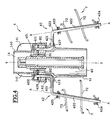
- Reducer includes a pinion central 81 fixed around the sleeve 40, pinions planetary 82 respectively associated with arms 42, and a fixed crown 142 secured to the end inner bottom of a cap 14 fixed under the cover 13.
- Each arm 42 includes a third branch 426 extending the radial branch 421 and perpendicular to it.
- a right angle elbow 427 between branches 421 and 426 is embedded in a radial projection 413 of the cap 41 in material plastic, which strengthens the connection between the arm 42 and the cap 41.
- the third branch 426 opens into a semi-cylindrical recess 414 of the cap, above projection 413.
- the cylindrical cap 41 secured arms 42 each supporting a whip turns at a speed lower than the predetermined speed, around the upper end 401 of the sleeve 40 which supports by a shoulder 402 the end top 411 of the cap.
- the cylindrical cap 14 comprising the crown internal tooth 142 covers the upper end of the cap 41 to the projections 413 so that the ring gear meshes with the pinions 82 of the reducer.
- the cap 14 partly comprises upper one 140 cylindrical barrel and three fins 141 regularly distributed around it for fit into corresponding housings on the inner underside of the tank cover 13 and glued into them.
- the whip device according to the invention is particularly well suited for whipping whites egg poured into the bottom of the tank 1 and mount them gradually in snow.
- the whips 7 gradually start to rotate around the axes AA of the arms branches 422, thus creating the optimal conditions to give a maximum volume to the preparation, this passing gradually from a low VP volume shown at the Figure 1 at a larger volume VP 'shown in figure 6. Whipping the present preparation thus a progressively increasing speed, which avoids centrifugation of blanks on the surface internal of the wall 10 of the tank.
- the whip device is initially subjected to two identical forces F1 and F2 of the same direction and constant intensity on either side of the center of gravity of the whip 7 located substantially on the axis of AA rotation when food preparation L of VP volume is stationary at the start of preparation culinary.
- F1 and F2 the linear speed of the liquid to the outer frustoconical portion 21 of the background is greater than the linear speed of this same liquid to the internal frustoconical portion 20 of the bottom and central skirt 23.
- the two forces substantially identical F1 and F2 submit whip 7 to an external torque (d1.F1) relative to the YY axis different from an internal torque (d2.F2) compared to the YY axis, this difference in couples creating the rotation of the whip around the arm branch 422.
Landscapes
- Chemical & Material Sciences (AREA)
- Chemical Kinetics & Catalysis (AREA)
- Engineering & Computer Science (AREA)
- Mechanical Engineering (AREA)
- Food Science & Technology (AREA)
- Food-Manufacturing Devices (AREA)
Abstract
Description
La présente invention concerne un dispositif à fouet entraíné en rotation dans une cuve d'un appareil de préparation culinaire. Ce dispositif à fouet est conçu spécialement pour fouetter des blancs d'oeuf en neige, ou pour battre d'autres émulsions telles qu'un mélange de jaunes d'oeuf et d'huile émulsionnés ensemble pour obtenir de la mayonnaise, ou bien encore pour préparer une crème Chantilly ou une crème fouettée à partir de crème fraíche ou de crème fleurette.The present invention relates to a device for whisk rotated in a bowl of a food preparation appliance. This device whisk is specially designed for whipping whites egg in snow, or to beat other emulsions such as a mixture of egg yolks and oil emulsified together to make mayonnaise, or even to prepare a whipped cream or a whipped cream from fresh cream or whipping cream.
Dans des appareils de préparation culinaire, dits également petits robots ménagers, le dispositif à fouet est entraíné en rotation par l'arbre moteur de l'appareil à une vitesse relativement faible constante comprise entre 500 et 700 tours/mn. Dans certains appareils, la vitesse constante de rotation peut être sélectionnée par paliers de quelques dizaines de tours/mn. Lorsque la vitesse de rotation de l'arbre moteur est trop élevée, certains dispositifs à fouet incorporent un réducteur de vitesse s'engrenant avec une extrémité de l'arbre moteur.In food preparation devices, also called small household robots, the device whip is rotated by the motor shaft the device at a relatively low speed constant between 500 and 700 rpm. In some devices, the constant speed of rotation can be selected in increments of a few tens of revolutions / min. When the speed of rotation motor shaft is too high, some whip devices incorporate a reducer gear meshing with one end of the shaft engine.
Le dispositif à fouet peut comprendre deux fouets diamétralement opposés qui tournent solidairement avec l'arbre moteur. Par exemple chaque fouet a la forme d'un vé plan en matière plastique contenu dans un plan radial à l'arbre moteur et ayant des ailes planes relativement larges, ajourées par des fentes verticales et horizontales. L'une des ailes du vé est libre et frôle la paroi interne de la cuve de l'appareil, et l'autre aile du vé est solidaire d'un capuchon monté sur une extrémité de l'arbre moteur. Deux tels fouets en vé à ailes larges planes sont monolithiques avec le capuchon pour être fabriqués en une seule pièce moulée en matière plastique.The whip device can include two diametrically opposite whips that rotate in solidarity with the motor shaft. For example each whip shaped like a flat plastic contained in a plane radial to the motor shaft and having relatively wide flat wings, perforated by vertical and horizontal slits. One of wings of the vee is free and grazes the internal wall of the tank of the apparatus, and the other wing of the vee is secured to a cap mounted on one end of the drive shaft. Two such wide-wing vee whips planes are monolithic with the cap to be manufactured in a single molded material plastic.
Dans d'autres appareils de préparation culinaire, le fouet est constitué par plusieurs fils métalliques développés sensiblement suivant des génératrices d'un tronc de cône et liés à une rondelle traversée par une broche centrale et située à la grande base du tronc de cône. La broche est encliquetée dans un fourreau excentré d'une plaque tournant avec l'arbre moteur de l'appareil, afin que la broche décrive un cercle autour de l'axe de l'arbre de l'appareil et simultanément le fouet tourne sur lui-même au moyen d'un engrenage réducteur entre l'axe du fouet et l'arbre moteur.In other preparation devices culinary, the whisk is made up of several wires metallic developed substantially according to generating a truncated cone and linked to a washer crossed by a central spindle and located at the large base of the truncated cone. The pin is snapped into an eccentric sheath of a plate rotating with the motor shaft of the device, so that the pin describes a circle around the axis of the device shaft and simultaneously the whip turns on itself by means of a reduction gear between the axis of the whip and the motor shaft.
Dans tous ces dispositifs à fouet, la rotation du fouet sur lui-même est créée par des moyens mécaniques d'entraínement en rotation entre l'arbre moteur et un support, capuchon ou broche, du fouet. La rotation du fouet débute avec la mise en marche de l'appareil à une vitesse constante directement proportionnelle à la vitesse de rotation de l'arbre moteur. Le passage brusque du fouet de l'état immobile à l'état rotatif à une vitesse relativement élevée n'est pas propice à une montée convenable de blancs d'oeuf en neige ou de toute émulsion à fouetter ou battre. En effet, au démarrage de la rotation de l'arbre moteur et du dispositif à fouet avec la rotation du ou des fouets sur eux-mêmes, une partie des blancs d'oeuf est centrifugée contre la surface interne de la paroi de la cuve.In all these whip devices, the rotation whip on itself is created by means mechanical rotational drive between the shaft motor and a support, cap or pin, of the whisk. The rotation of the whisk begins with the start of the device at a constant speed directly proportional to the shaft rotation speed engine. The sudden passage of the state whip stationary in the rotating state at a relatively speed high is not conducive to a suitable climb of egg whites or any emulsion whip or beat. Indeed, at the start of the rotation of the motor shaft and the whip device with the rotation of the whip (s) on themselves, a part of the egg whites is centrifuged against the internal surface of the tank wall.
La demande de brevet français FR-2 282 932 et le brevet allemand DE-402 411 divulguent un appareil mélangeur comprenant un organe agitateur qui tourne librement autour d'un bras incliné à 45° ou perpendiculaire à un arbre d'entraínement situé au centre d'une cuve. Selon la demande de brevet précitée, l'organe agitateur peut se déplacer sur le bras devant une butée à l'extrémité libre du bras et est constitué d'une plaque circulaire axiale au bras et sur laquelle des tiges de différentes longueurs sont disposées. Selon le brevet allemand précité, le bras autour duquel l'organe agitateur tourne est situé au voisinage de la partie supérieure de la cuve et a une forme en double trapèze isocèle si bien que la matière à mélanger est surtout brassée au niveau des parois de la cuve.French patent application FR-2 282 932 and the German patent DE-402 411 discloses an apparatus mixer comprising a rotating agitating member freely around an arm inclined at 45 ° or perpendicular to a drive shaft located at center of a tank. According to the patent application mentioned above, the agitating member can move on the arm in front of a stop at the free end of the arm and consists of an axial circular plate on the arm and on which rods of different lengths are arranged. According to the aforementioned German patent, the arm around which the agitator rotates is located near the upper part of the tank and has a double isosceles trapezoid shape so that the material to be mixed is mostly brewed at the level of the walls of the tank.
Les organes agitateurs connus précités ne sont pas bien adaptés pour battre des émulsions peu denses telles que des blancs d'oeufs. L'organe agitateur selon la demande FR-2 282 932 est lourd et a tendance à remonter le long du bras. L'organe agitateur selon le brevet DE-402 411 tourne autour d'un axe perpendiculaire à l'axe de rotation moteur et situé au-dessus du mélange et est soumis de manière discontinue à la résistance du mélange et donc déséquilibré.The aforementioned known agitating bodies are not not well suited to beat sparse emulsions such as egg whites. The agitating organ according to demand FR-2 282 932 is heavy and tends to go up along the arm. The agitating organ according to patent DE-402 411 revolves around an axis perpendicular to the motor rotation axis and located above the mixture and is subjected so discontinuous to the resistance of the mixture and therefore imbalance.
L'objectif de l'invention est de fournir un dispositif à fouet pour appareil de préparation culinaire dans lequel des émulsions peu denses, telles que des blancs d'oeuf ou analogues, sont fouettés ou battus avec au moins un fouet tournant librement à une vitesse de rotation d'abord lente puis progressivement de plus en plus élevée, dès le démarrage de la rotation de l'arbre moteur de l'appareil, sans que le fouet vibre. The objective of the invention is to provide a whip device for preparation apparatus culinary in which sparse emulsions, such as egg whites or the like are whipped or beaten with at least one rotating whip freely at first slow rotation speed then progressively higher and higher, from starting the rotation of the motor shaft the appliance, without the whip vibrating.
A cette fin, un dispositif à fouet pour un appareil de préparation culinaire qui comprend un arbre rotatif moteur, une cuve ayant un fond qui, en demi-coupe axiale suivant l'arbre moteur, a un profil sensiblement symétrique par rapport à un axe prédéterminé, un bras ayant une première branche entraínée en rotation autour de l'axe de la cuve par l'arbre moteur et une deuxième branche s'étendant suivant ledit axe prédéterminé vers le fond de la cuve, et un fouet monté à rotation libre autour de la deuxième branche, est caractérisé en ce que le fouet comprend une première portion hélicoïdale tronconique axée autour de la deuxième branche de bras et ayant une petite base montée à rotation libre autour de la deuxième branche de bras, la première portion hélicoïdale ayant un angle au sommet sensiblement égal à l'angle au sommet d'une partie en vé du fond de cuve vu en coupe axiale.To this end, a whip device for a food preparation appliance which includes a rotary motor shaft, a tank having a bottom which, in axial half-section along the drive shaft, has a profile substantially symmetrical about an axis predetermined, an arm having a first branch rotated around the axis of the tank by the drive shaft and a second branch extending along said predetermined axis towards the bottom of the tank, and a whip mounted with free rotation around the second branch, is characterized in that the whip includes a first frustoconical helical portion focused around the second arm branch and having a small base mounted with free rotation around the second arm branch, the first portion helical having an apex angle substantially equal to the angle at the top of a bottom vee tank seen in axial section.
Le fouet selon l'invention peut comprendre une deuxième portion hélicoïdale tronconique ayant une grande base commune avec la première portion hélicoïdale tronconique et une petite base montée à rotation libre autour de la deuxième branche de bras.The whip according to the invention can comprise a second frustoconical helical portion having a large common base with the first portion frustoconical helical and a small base mounted at free rotation around the second arm branch.
Bien que les pas des première et deuxième portions hélicoïdales tronconiques du dispositif puissent être identiques, c'est-à-dire le pas dans le fouet hélicoïdal est constant, les première et deuxième portions hélicoïdales tronconiques du dispositif peuvent avoir des pas différents pour mieux équilibrer le fouet selon l'invention. En variante, la première portion hélicoïdale tronconique du dispositif a un pas augmentant progressivement depuis la petite base montée à rotation libre de celle-ci vers la grande base commune, et la deuxième portion hélicoïdale tronconique a un pas diminuant progressivement depuis la grande base commune vers la petite base montée à rotation libre de celle-ci.Although the steps of the first and second tapered helical portions of the device can be identical, that is to say the step in the helical whip is constant, the first and second tapered helical portions of the device may have different steps for better balance the whip according to the invention. In variant, the first frustoconical helical portion of the device has a step increasing gradually from the small base mounted with free rotation of this one towards the large common base, and the second tapered helical portion has a decreasing pitch gradually from the large common base towards the small base mounted with free rotation thereof.
Le montage à rotation libre, dit montage fou, du fouet autour du bras autorise le fouet à tourner à une très faible vitesse par rapport à l'arbre moteur au début du démarrage de ce dernier, et à une vitesse progressivement de plus en plus élevée lorsque la préparation culinaire devient plus volumineuse.The free rotation assembly, called crazy assembly, of the whip around the arm allows the whip to rotate very low speed compared to the motor shaft at the start of the start of the latter, and at a speed gradually higher and higher when the culinary preparation becomes more voluminous.
Le fouet comporte ainsi une première portion d'hélice ayant un profil similaire au profil sensiblement symétrique du fond. Des portions annulaires aux extrémités du fouet sont guidées librement autour de la deuxième branche de bras et maintenues entre des butées respectives sur la deuxième branche de bras afin que le fouet soit maintenu dans la cuve. Les butées sont par exemple amovibles ou intégrées à la deuxième branche par déformation. Entre ces butées, le fouet est monté à rotation libre de manière à maintenir le fouet à une position constante en hauteur dans la cuve pour affleurer le fond de la cuve. Ainsi, le fouet comporte des portions annulaires guidées librement autour de la deuxième branche de bras et maintenues entre des butées respectives sur la deuxième branche de bras. De préférence, les portions annulaires sont des boucles circulaires d'extrémité d'un fil métallique cintré constituant ledit fouet.The whisk thus has a first portion propeller with a profile similar to the profile substantially symmetrical to the bottom. Portions annulars at the ends of the whip are guided freely around the second arm branch and held between respective stops on the second arm branch so that the whip is kept in the tank. The stops are for example removable or integrated into the second branch by deformation. Between these stops, the whip is mounted at free rotation so as to keep the whisk at a constant height position in the tank for flush the bottom of the tank. So the whip has freely guided annular portions around the second arm branch and held between respective stops on the second branch of arms. Preferably, the annular portions are circular loops at the end of a wire bent metal constituting said whip.
En fonction du volume de la préparation culinaire, deux bras ou plus peuvent être prévus. Par exemple, le dispositif à fouet comprend deux fouets montés à rotation libre autour de deuxièmes branches de deux bras symétriques par rapport à l'axe de la cuve et entraínés ensemble en rotation autour de l'axe de la cuve par l'arbre moteur.Depending on the volume of the preparation culinary, two or more arms can be provided. Through example, the whip device has two whips mounted with free rotation around second branches of two arms symmetrical about the axis of the tank and driven together rotating around the axis of the tank by the motor shaft.
Selon une réalisation à liaison directe entre arbre moteur et porte-accessoire, tel que le dispositif à fouet, le dispositif à fouet comprend un capuchon porte-fouet cylindrique qui est fixé de manière amovible autour de l'arbre moteur et auquel la première branche de bras est fixée. Le bras peut comprendre une troisième branche, de préférence parallèle à l'axe de la cuve, reliée à la première branche et sensiblement noyée dans le capuchon porte-fouet cylindrique de manière à renforcer la liaison métal/matière plastique entre bras et capuchon. De préférence, le capuchon porte-fouet entoure une jupe centrale de la cuve entourant sans contact l'arbre moteur afin de protéger le bloc-moteur de l'appareil au niveau de l'arbre moteur contre toute pénétration d'aliments.According to an embodiment with direct connection between motor shaft and accessory holder, such as the whip device, the whip device includes a cylindrical whisk holder cap which is attached removably around the motor shaft and to which the first arm branch is attached. The arm can understand a third branch, preferably parallel to the axis of the tank, connected to the first branch and substantially embedded in the whip holder cap cylindrical so as to strengthen the bond metal / plastic between arms and cap. Of preferably the whip-holder cap surrounds a skirt tank center without contact around the shaft engine to protect the unit's engine block at the motor shaft against penetration of food.
Selon une autre réalisation à liaison indirecte par réducteur de vitesse entre arbre moteur et porte-accessoire, le dispositif à fouet comprend un réducteur de vitesse ayant un pignon central fixé de manière amovible autour de l'arbre moteur et un pignon planétaire engrenant dans le pignon central, et une troisième branche du bras reliée par un coude noyé dans un capuchon porte-fouet cylindrique à la première branche de bras. Le pignon planétaire est monté à rotation autour de la troisième branche. Le capuchon porte-fouet est monté à rotation de manière amovible autour de l'arbre moteur et soutenu par celui-ci et de préférence entoure une jupe centrale de la cuve entourant sans contact l'arbre moteur.According to another embodiment with indirect link by speed reducer between motor shaft and accessory holder, the whip device includes a speed reducer having a fixed central pinion of removably around the motor shaft and a planetary gear meshing in the central gear, and a third arm branch connected by an elbow embedded in a cylindrical whip holder cap at the first arm branch. The planetary gear is rotatably mounted around the third leg. The whip holder cap is rotatably mounted removable around the motor shaft and supported by this and preferably surrounds a central skirt of the tank surrounding the motor shaft without contact.
Le dispositif à fouet peut comprendre en outre un chapeau fixé sous un couvercle de la cuve, recouvrant au moins une partie du capuchon porte-fouet dans laquelle le pignon planétaire est logé, et comportant une couronne dentée interne s'engrenant avec le pignon planétaire et entourant le pignon central.The whip device may further comprise a cap fixed under a cover of the tank, covering at least part of the whip holder cap in which the planetary gear is housed, and having an internal gear ring meshing with the planetary gear and surrounding the gear central.
De préférence, chaque bras est une tige métallique coudée et le capuchon porte-fouet est en matière plastique.Preferably, each arm is a rod angled metal and the whip holder cap is plastic material.
D'autres caractéristiques et avantages de la présente invention apparaítront plus clairement à la lecture de la description suivante de plusieurs réalisations préférées de l'invention en référence aux dessins annexés correspondants dans lesquels :
- la figure 1 est une vue en coupe axiale schématique d'une cuve à fond en W pour un appareil de préparation culinaire présentant un arbre moteur saillant verticalement dans la cuve depuis un bloc moteur et lié directement à un dispositif à fouet selon l'invention ;
- la figure 2 est une vue en perspective d'un dispositif à deux fouets hélicoïdaux selon l'invention ;
- les figures 3, 4 et 5 sont des vues en perspective, en coupe axiale et en perspective éclatée d'un dispositif à deux fouets comportant un réducteur de vitesse intégré, respectivement ; et
- la figure 6 est une vue en coupe axiale analogue à la figure 1 montrant l'augmentation de volume d'une préparation culinaire après fouettage ainsi que des couples entraínant en rotation un fouet sur lui-même, comparativement à la figure 1 au tout début de la rotation de l'arbre moteur.
- Figure 1 is a schematic axial sectional view of a tank with a W bottom for a food preparation appliance having a drive shaft projecting vertically into the tank from an engine block and directly connected to a whisk device according to the invention;
- Figure 2 is a perspective view of a device with two helical whips according to the invention;
- Figures 3, 4 and 5 are perspective views, in axial section and in exploded perspective of a device with two whips having an integrated speed reducer, respectively; and
- Figure 6 is an axial sectional view similar to Figure 1 showing the increase in volume of a culinary preparation after whipping as well as couples causing a whisk to rotate on itself, compared to Figure 1 at the very beginning of the rotation of the motor shaft.
En référence à la figure 1, une cuve 1 en
matière plastique de préférence transparente pour
appareil de préparation culinaire présente une
symétrie axiale autour d'un axe vertical YY.Referring to Figure 1, a
Selon la réalisation illustrée, la cuve présente
un fond 20-21 dont le profil en coupe axiale est en
forme de W, c'est-à-dire de deux vés symétriques par
rapport à l'axe YY, qui ont des sommets 22 formant un
pied circulaire de la cuve autour de l'axe YY et qui
sont reliés par une jupe cylindrique centrale 23
proéminente dans la cuve. Les branches internes des
vés du W reliées à la base de la jupe 23 sont des
génératrices d'une portion tronconique interne 20 du
fond dont la grande base est formée par le pied
circulaire 22 et dont la petite base supporte la jupe
cylindrique 23. Les branches externes des vés du W
sont des génératrices d'une portion tronconique
externe 21 du fond dont la petite base est formée par
le pied circulaire 22 et dont la grande base est
emboítée et fixée par collage à la grande base
inférieure d'une paroi 10, cylindrique ou
sensiblement en calotte sphérique 10 de la cuve 1. La
jonction circulaire 11 entre la grande base de la
portion tronconique externe 21 du fond de cuve et la
paroi de cuve 10 est à un niveau supérieur à la
petite base de la portion tronconique interne 20 du
fond de cuve supportant la jupe 23 par rapport au
pied 22 commun aux portions tronconiques 20 et 21.
Cette différence de niveaux est due à ce que les
génératrices des portions tronconiques 20 et 21 dans
un demi-plan axial sont symétriques par rapport à un
axe oblique AA passant par le sommet 22 du vé
respectif du W et interceptant l'axe YY en un point
relativement éloigné de l'ouverture supérieure 12 de
la cuve pouvant être fermée hermétiquement par un
couvercle 13. L'axe AA est en fait une génératrice
d'un cône dont la base est formée par le pied
circulaire 22, qui est centré sur l'axe de symétrie
YY et qui présente un demi-angle au sommet α compris
entre 5° et 15°, de préférence 10° environ.According to the illustrated embodiment, the tank has
a bottom 20-21 whose profile in axial section is in
W shape, i.e. two symmetrical ves by
relative to the YY axis, which have
La portion tronconique interne 20 du fond de
cuve présente une cavité tronconique située sous la
cuve ayant des pattes 24 pour fixer la cuve autour
d'une protubérance tronconique 30 d'un socle 3 de
l'appareil de préparation culinaire, le pied
circulaire 22 de la cuve reposant sur le socle de la
cuve. Le socle 3 constitue le bloc-moteur de
l'appareil de préparation culinaire.The internal
Un arbre moteur 31 rotatif autour de l'axe de
symétrie YY saille de la protubérance 30 du socle 3
et traverse sans contact la jupe 23 de la cuve.
L'extrémité supérieure 32 de l'arbre 31 incluse dans
la jupe 23 présente une section non circulaire, par
exemple hexagonale, de manière à s'emboíter en butée
dans un manchon 40 d'un porte-accessoire 4, de
section hexagonale interne complémentaire. Selon la
réalisation illustrée, le porte-accessoire 4 comporte
un capuchon de protection cylindrique 41 terminé par
un épaulement supérieur 411 lié par collage ou
assemblé par sections polygonales 412 à la périphérie
supérieure du manchon 40. Le manchon de protection 41
entoure la majeure partie supérieure de la jupe 23 de
manière à éviter la pénétration d'aliments dans
celle-ci. Lorsque l'arbre 31 tourne, le manchon 40
tourne dans la jupe sans frottement avec celle-ci et
le capuchon de protection 41 tourne autour de la jupe
sans frottement avec celle-ci.A
Selon l'invention, le porte-accessoire est un
porte-fouet 4. Le porte-fouet comprend, outre le
manchon 40 et le capuchon 41, au moins un bras coudé
42 supportant un fouet 7, ou deux bras 42
diamétralement opposés supportant chacun un fouet
comme montré dans la figure 2. Le bras 42 est une
tige métallique coudée et comporte une première
branche 421 qui s'étend radialement au capuchon 41 et
dont une extrémité y est noyée lors du moulage de
celui-ci, le capuchon et le manchon 40 étant en
matière plastique. L'autre extrémité de la branche
421 est reliée par un coude obtus 423 à une deuxième
branche 422 du bras 42, plus longue que la première
branche 421. La branche 422 s'étend suivant l'axe AA,
c'est-à-dire s'étend dans un plan axial au porte-fouet
4 et à la cuve 1 et est inclinée de l'angle
aigu α par rapport à l'axe de rotation YY du porte-fouet
4.According to the invention, the accessory holder is a
En variante, le porte-fouet comprend deux bras
supportant chacun deux fouets, ou trois ou quatre
bras supportant chacun un fouet, régulièrement
répartis autour du capuchon 41 et positionnés dans
des sections axiales de la cuve d'une manière
analogue au bras du fouet 7 décrit ci-après.Alternatively, the whisk holder includes two arms
each supporting two whips, or three or four
arms each supporting a whip, regularly
distributed around the
En référence à la figure 2, deux fouets 7 sont
montés respectivement entre des butées 424 et 425 de
deux bras 42. Les butées 424 et 425 sont prévues
respectivement à l'extrémité libre de la deuxième
branche de bras 422 sous une portion annulaire de
guidage inférieure 74 du fouet 7 et à proximité de
l'autre extrémité de la branche 422, sous le coude
423, et plus précisément juste au-dessus d'une
portion annulaire de guidage supérieure 75 du fouet
7. Les butées 424 et 425 sont des rondelles à griffe
engagées dans des gorges adéquates de la branche 422,
ou bien des déformations en forme de renflements
sensiblement semi-toriques sur la branche 422. Les
butées 424 et 425 empêchent de monter ou de descendre
le fouet le long de la deuxième branche de bras 422.
Le fouet 7 est ainsi monté à rotation libre autour de
la branche 422 et immobile en translation avec faible
jeu entre les butées 424 et 425.Referring to Figure 2, two
Chaque fouet 7 est un fil métallique inoxydable
conformé en double hélice tronconique, de faible
section, typiquement de 2 mm.Each
Le fouet 7 est conformé à partir d'une portion
de guidage annulaire inférieure 74 formée par une
boucle torique butant sur la butée inférieure 424
jusqu'à une portion de guidage annulaire supérieure
75 formée par une deuxième boucle torique butant sous
la butée supérieure 425, en une hélice tronconique
inférieure 72 puis en une hélice tronconique
supérieure 73. Les portions de guidage annulaires 74
et 75 aux extrémités du fouet 7 sont montées à
rotation libre avec un léger jeu autour de la
deuxième branche de bras 422. Les hélices sont de
même sens et ont une grande base commune située
sensiblement dans un plan médiateur à la branche 422
entre les butées 424 et 425 qui sont situées
sensiblement aux sommets des hélices 72 et 73
respectivement. Les hélices 72 et 73 comprennent
chacune une à trois spires environ et ont des
longueurs sensiblement identiques.
Afin qu'un liquide plus ou moins visqueux L soit
battu ou fouetté convenablement au niveau du fond 20-21
de la cuve 1, les dimensions de chaque fouet 7
sont telles que le fouet balaye quasiment un volume à
section losangique ou carrée VF, autour de la jupe de
cuve 23, entre les portions tronconiques 20 et 21 du
fond comme montré à la figure 1, lorsque le porte-fouet
4 solidaire en rotation de l'arbre moteur 31
tourne autour de l'axe de symétrie YY de la cuve 1 et
lorsque le fouet 7 est entraíné en rotation libre
autour de l'axe AA de la deuxième branche 422 du bras
42. Cette rotation libre est due au déplacement
résistant du fouet dans le liquide L lors de la
rotation du porte-fouet.So that a more or less viscous liquid L is
beaten or whipped properly at the bottom 20-21
of the
L'hélice inférieure 72 et la portion annulaire
74 du fouet 7 avoisinent respectivement les portions
tronconiques du fond 20-21 et le pied de cuve 22 de
quelques millimètres, typiquement de 3 à 5 mm. Le
fouet 7 tourne ainsi dans un volume en forme de
couronne circulaire à section radiale en V autour de
l'axe YY délimité sensiblement par la moitié
inférieure du losange ou carré VF centré sur l'axe
AA, comme montré à la figure 1. En particulier,
l'angle au sommet du cône dans lequel l'hélice
inférieure 72 tourne sur elle-même est sensiblement
égale à l'angle au sommet du vé circulaire formé par
les portions de fond tronconiques 20 et 21. La
hauteur de l'hélice 72 est sensiblement égale à celle
du vé de fond 20-21. Typiquement, chaque hélice 72,
73 a un diamètre de grande base de 70 mm environ, une
hauteur comprise entre 40 et 70 mm environ, et un
angle au sommet compris entre 45° et 60° environ.The
Le fouet 7 selon l'invention présente un coût de
fabrication relativement faible et est bien adapté à
fouetter des émulsions peu denses, telles que des
blancs d'oeuf. Pour des vitesses relativement élevées
de l'arbre moteur et du porte-fouet, supérieures à
500 tours/mn environ, le fouet 7 ne vibre pas puisque
son centre de gravité est sensiblement situé sur
l'axe de rotation de fouet AA le long de la branche
de bras 422, ne créant ainsi aucun déséquilibre dans
l'ensemble fouet et bras.The
De manière à mieux équilibrer encore le fouet 7,
le pas de l'hélice inférieure 72 croít
progressivement depuis la petite base de l'hélice 72
formée par la portion de guidage annulaire inférieure
74 vers la grande base, puis le pas de l'hélice
supérieure 73 décroít progressivement depuis la
grande base vers la petite base de l'hélice 73 formée
par la portion de guidage annulaire supérieure 75.In order to better balance the
En référence aux figures 3, 4 et 5, le porte-fouet
4 comprend un réducteur de vitesse de rotation
intégré au porte-fouet. Le réducteur inclut un pignon
central 81 fixé autour du manchon 40, des pignons
planétaires 82 respectivement associés aux bras 42,
et une couronne fixe 142 solidaire de l'extrémité
inférieure interne d'un chapeau 14 fixé sous le
couvercle 13.With reference to Figures 3, 4 and 5, the
Chaque bras 42 comprend une troisième branche
426 prolongeant la branche radiale 421 et
perpendiculaire à celle-ci. Un coude à angle droit
427 entre les branches 421 et 426 est noyé dans une
saillie radiale 413 du capuchon 41 en matière
plastique, ce qui renforce la liaison entre le bras
42 et le capuchon 41. La troisième branche 426
débouche dans un évidement semi-cylindrique 414 du
capuchon, au-dessus de la saillie 413.Each
Autour de l'extrémité de la branche de bras 426
est monté à rotation l'un des pignons planétaires 82
qui est logé dans l'évidement 414. Lorsque le manchon
40 avec l'arbre moteur 31 tourne à une vitesse
prédéterminée, le capuchon cylindrique 41 solidaire
des bras 42 supportant chacun un fouet tourne à une
vitesse plus petite que la vitesse prédéterminée,
autour de l'extrémité supérieure 401 du manchon 40
qui soutient par un épaulement 402 l'extrémité
supérieure 411 du capuchon. Around the end of the
Le chapeau cylindrique 14 comportant la couronne
dentée interne 142 couvre l'extrémité supérieure du
capuchon 41 jusqu'aux saillies 413 pour que la
couronne dentée s'engrène sur les pignons 82 du
réducteur. Le chapeau 14 comporte en partie
supérieure un fût cylindrique 140 et trois ailettes
141 régulièrement réparties autour de celui-ci pour
s'emboíter dans des logements correspondants ménagés
sur la face inférieure interne du couvercle de cuve
13 et collés dans ceux-ci.The
Le dispositif à fouet selon l'invention est
particulièrement bien adapté pour fouetter des blancs
d'oeuf versés dans le fond de la cuve 1 et les monter
progressivement en neige.The whip device according to the invention is
particularly well suited for whipping whites
egg poured into the bottom of the
Grâce à la rotation libre des fouets 7 autour
des axes formés par les deuxièmes branches de bras
422, c'est-à-dire leur montage fou autour de ces
branches, le mouvement en rotation des fouets sur
eux-mêmes est dû à la résultante du travail des
forces pendant la préparation culinaire. Au tout
début de préparation, telle que des blancs d'oeuf, il
n'existe quasiment pas de mouvement de rotation des
fouets autour de leurs branches de bras 422, lors du
démarrage de la rotation de l'arbre moteur 30 et du
porte-fouet 4 autour de l'axe YY. Dès que la
préparation acquiert une certaine consistance, qui a
tendance à "freiner" la rotation des bras autour de
l'axe YY, les fouets 7 se mettent progressivement à
tourner autour des axes AA des branches de bras 422,
créant ainsi les conditions optimales pour donner un
maximum de volume à la préparation, celle-ci passant
progressivement d'un volume faible VP montré à la
figure 1 à un volume plus grand VP' montré à la
figure 6. Le fouettage de la préparation présente
ainsi une vitesse croissante progressivement, ce qui
évite une centrifugation des blancs sur la surface
interne de la paroi 10 de la cuve.Thanks to the free rotation of the
Le dispositif à fouet est soumis initialement à
deux forces identiques F1 et F2 de même direction et
d'intensité constante de part et d'autre du centre de
gravité du fouet 7 situé sensiblement sur l'axe de
rotation AA lorsque la préparation culinaire L de
volume VP est immobile au début de la préparation
culinaire. Lorsque le porte-fouet 4 commence à
tourner autour de l'axe YY, la vitesse linéaire du
liquide vers la portion tronconique externe 21 du
fond est supérieure à la vitesse linéaire de ce même
liquide vers la portion tronconique interne 20 du
fond et la jupe centrale 23. Les deux forces
sensiblement identiques F1 et F2 soumettent le fouet
7 à un couple externe (d1.F1) par rapport à l'axe YY
différent d'un couple interne (d2.F2) par rapport à
l'axe YY, cette différence de couples créant la
rotation du fouet autour de la branche de bras 422.The whip device is initially subjected to
two identical forces F1 and F2 of the same direction and
constant intensity on either side of the center of
gravity of the
Lorsque la viscosité dynamique de la préparation
culinaire L augmente, les deux forces identiques
précitées F1 et F2 deviennent des forces F1' et F2'
inégales de part et d'autre du centre de gravité du
fouet. Le volume de préparation VP' devient plus
grand et entoure la base de la jupe 23 et atteint la
jonction 11 au-dessus du fond 20-21, comme montré à
la figure 6. Les distances d1' et d2' des points
d'application des forces plus grandes F1' et F2' ont
tendance à croítre depuis l'axe de rotation AA, tout
en montant en direction du couvercle 13, ce qui
augmente la vitesse de rotation du fouet. Avec le
fouet hélicoïdal 7 selon l'invention, comparativement
aux fouets ou agitateurs connus, la composante
d'élévation du fouet est plus rapidement prononcée,
grâce à l'entrée d'air dans les hélices 72 et 73.When the dynamic viscosity of the preparation
culinary L increases, the two identical forces
aforementioned F1 and F2 become forces F1 'and F2'
unequal on either side of the center of gravity of the
whip. The volume of preparation VP 'becomes more
large and surrounds the base of the
Claims (11)
Applications Claiming Priority (2)
| Application Number | Priority Date | Filing Date | Title |
|---|---|---|---|
| FR9800824A FR2773698B1 (en) | 1998-01-22 | 1998-01-22 | WHIP DEVICE FOR FOOD PREPARATION APPARATUS |
| FR9800824 | 1998-01-22 |
Publications (1)
| Publication Number | Publication Date |
|---|---|
| EP0931493A1 true EP0931493A1 (en) | 1999-07-28 |
Family
ID=9522187
Family Applications (1)
| Application Number | Title | Priority Date | Filing Date |
|---|---|---|---|
| EP99400096A Ceased EP0931493A1 (en) | 1998-01-22 | 1999-01-15 | Whipping tool for a kitchen robot |
Country Status (2)
| Country | Link |
|---|---|
| EP (1) | EP0931493A1 (en) |
| FR (1) | FR2773698B1 (en) |
Cited By (4)
| Publication number | Priority date | Publication date | Assignee | Title |
|---|---|---|---|---|
| DE102008031247A1 (en) | 2008-07-02 | 2010-01-07 | BSH Bosch und Siemens Hausgeräte GmbH | Stirring tool, in particular for a kitchen appliance |
| CN104738112A (en) * | 2015-04-16 | 2015-07-01 | 上海麦科食品机械有限公司 | Disc type leavening assembly for full-automatic cake leavening device |
| GB2522899A (en) * | 2014-02-10 | 2015-08-12 | Kenwood Ltd | Food blender |
| EP2969164A4 (en) * | 2013-03-15 | 2016-10-26 | Nano One Materials Corp | Reactor vessel for complexecelle formation |
Families Citing this family (5)
| Publication number | Priority date | Publication date | Assignee | Title |
|---|---|---|---|---|
| CN103170279A (en) * | 2013-03-27 | 2013-06-26 | 印峰 | Improved stirring blades for stirrer |
| FR3079125B1 (en) * | 2018-03-23 | 2023-01-20 | Seb Sa | MIXER ACCESSORY FOR A HOUSEHOLD APPLIANCE FOR CULINARY PREPARATION, EQUIPPED WITH EASILY REMOVABLE WHISK(S) |
| FR3079124B1 (en) | 2018-03-23 | 2021-03-05 | Seb Sa | BEATER ACCESSORY FOR A CULINARY PREPARATION APPLIANCE, SUITABLE FOR MIXING LOW QUANTITIES OF FOOD PREPARATION |
| CN112089340B (en) * | 2020-09-18 | 2025-10-03 | 惠州拓邦电气技术有限公司 | Feeding device and automatic cooking machine |
| CN117282304B (en) * | 2023-11-27 | 2024-01-26 | 河北亿达渤润科技有限公司 | Stirring device for lubricating oil production |
Citations (5)
| Publication number | Priority date | Publication date | Assignee | Title |
|---|---|---|---|---|
| DE402411C (en) | 1922-03-12 | 1924-09-19 | Robert Zapp Fa | Mixing and kneading machine with fixed trough |
| US1634563A (en) * | 1925-11-05 | 1927-07-05 | William N Shaw | Drug mixer |
| FR1231532A (en) * | 1959-07-30 | 1960-09-29 | Schoettle Kg Electrostar | Agitator for household appliances |
| FR2282932A1 (en) | 1974-08-26 | 1976-03-26 | Kimmel Hans | Mixing tool for mixers with epicyclic drive - comprises individual elements with protruding stirring rods arranged to prevent excessive frictional forces |
| DE4242289A1 (en) * | 1992-12-15 | 1994-06-16 | Bosch Siemens Hausgeraete | Universal food processor with key-operated safety switch - has teeth on exterior of tool coupling sleeve for rotation of shaft inclined at angle from end of cantilever arm |
Family Cites Families (2)
| Publication number | Priority date | Publication date | Assignee | Title |
|---|---|---|---|---|
| US1851325A (en) * | 1929-04-08 | 1932-03-29 | Jack W Puterbaugh | Mixing machine |
| FR2202669B1 (en) * | 1972-10-18 | 1976-04-02 | Zarzecki Jean |
-
1998
- 1998-01-22 FR FR9800824A patent/FR2773698B1/en not_active Expired - Fee Related
-
1999
- 1999-01-15 EP EP99400096A patent/EP0931493A1/en not_active Ceased
Patent Citations (5)
| Publication number | Priority date | Publication date | Assignee | Title |
|---|---|---|---|---|
| DE402411C (en) | 1922-03-12 | 1924-09-19 | Robert Zapp Fa | Mixing and kneading machine with fixed trough |
| US1634563A (en) * | 1925-11-05 | 1927-07-05 | William N Shaw | Drug mixer |
| FR1231532A (en) * | 1959-07-30 | 1960-09-29 | Schoettle Kg Electrostar | Agitator for household appliances |
| FR2282932A1 (en) | 1974-08-26 | 1976-03-26 | Kimmel Hans | Mixing tool for mixers with epicyclic drive - comprises individual elements with protruding stirring rods arranged to prevent excessive frictional forces |
| DE4242289A1 (en) * | 1992-12-15 | 1994-06-16 | Bosch Siemens Hausgeraete | Universal food processor with key-operated safety switch - has teeth on exterior of tool coupling sleeve for rotation of shaft inclined at angle from end of cantilever arm |
Cited By (6)
| Publication number | Priority date | Publication date | Assignee | Title |
|---|---|---|---|---|
| DE102008031247A1 (en) | 2008-07-02 | 2010-01-07 | BSH Bosch und Siemens Hausgeräte GmbH | Stirring tool, in particular for a kitchen appliance |
| EP2969164A4 (en) * | 2013-03-15 | 2016-10-26 | Nano One Materials Corp | Reactor vessel for complexecelle formation |
| GB2522899A (en) * | 2014-02-10 | 2015-08-12 | Kenwood Ltd | Food blender |
| GB2522899B (en) * | 2014-02-10 | 2017-11-08 | Kenwood Ltd | Food Blender |
| CN104738112A (en) * | 2015-04-16 | 2015-07-01 | 上海麦科食品机械有限公司 | Disc type leavening assembly for full-automatic cake leavening device |
| CN104738112B (en) * | 2015-04-16 | 2016-09-07 | 上海麦科食品机械有限公司 | Full-automatic cake whipping device disc-type dismisses assembly |
Also Published As
| Publication number | Publication date |
|---|---|
| FR2773698B1 (en) | 2000-05-12 |
| FR2773698A1 (en) | 1999-07-23 |
Similar Documents
| Publication | Publication Date | Title |
|---|---|---|
| FR2479772A1 (en) | HELICOPTER ROTOR INCLUDING ELASTOMERIC SEALS | |
| EP0931493A1 (en) | Whipping tool for a kitchen robot | |
| EP0622113B1 (en) | Stirrer especially for paint stirring machines | |
| EP2892405B1 (en) | Household food preparation apparatus comprising a dough-mixing hook driven in a planetary motion | |
| EP1018919B1 (en) | Accessories for preparing emulsions, foams and dispersions and electrical household, or domestic, appliance for cooking | |
| EP0820879A1 (en) | Stirring cover for paint container mounted on paint mixing machines | |
| FR2786385A1 (en) | HOUSEHOLD APPLIANCE FOR CULINARY PREPARATION, COMPRISING A KNEADING TOOL | |
| EP2211674B1 (en) | Container for electrical household food preparation appliance comprising a lower transmission component | |
| EP2850982A1 (en) | Device for driving a rotary tool for food processing apparatus, and food processing apparatus provided with such a drive device | |
| FR2929535A1 (en) | Agitation system for agitating e.g. cream, in vat, has strips and blades mechanically separated from each other and rotationally driven by distinct motors placed close to upper end of central shaft | |
| CA1300600C (en) | Mixer-emulsifier fool for electric household appliance used in food preparation | |
| EP1483996B1 (en) | Rotary working tool for electrical household food processor | |
| EP2870902B1 (en) | Emulsifier-stirrer tool for blender and hand-held blender provided with such a tool | |
| WO2017098169A1 (en) | Food preparation device | |
| EP0382092B1 (en) | Mixing device | |
| EP4404806B1 (en) | Whisk for a food preparation appliance | |
| EP1449576B1 (en) | Stirring device with axial propeller and lateral blades | |
| EP1923129A1 (en) | Mixing device with a rotating stirer moving the mixture toward a receptacle with holes, and corresponding parts | |
| EP3845103A1 (en) | Mixing device | |
| WO2023046921A1 (en) | Food-preparation appliance comprising a rotating accessory | |
| BE362393A (en) | ||
| FR2787038A1 (en) | Food mixer, beater and kneader has bowl with central duct surrounding motor shaft with drive mechanism and reduction gear mounted above it | |
| BE518318A (en) | ||
| CH322215A (en) | Assembly comprising a rotating shaft and a driven member mounted on this shaft | |
| CH148430A (en) | Mixer. |
Legal Events
| Date | Code | Title | Description |
|---|---|---|---|
| PUAI | Public reference made under article 153(3) epc to a published international application that has entered the european phase |
Free format text: ORIGINAL CODE: 0009012 |
|
| AK | Designated contracting states |
Kind code of ref document: A1 Designated state(s): BE DE GB IT LU NL |
|
| 17P | Request for examination filed |
Effective date: 19990724 |
|
| AKX | Designation fees paid |
Free format text: BE DE GB IT LU NL |
|
| GRAG | Despatch of communication of intention to grant |
Free format text: ORIGINAL CODE: EPIDOS AGRA |
|
| 17Q | First examination report despatched |
Effective date: 20020628 |
|
| STAA | Information on the status of an ep patent application or granted ep patent |
Free format text: STATUS: THE APPLICATION HAS BEEN REFUSED |
|
| 18R | Application refused |
Effective date: 20021223 |