EP0931639A2 - Rohrauskleidungsverfahren - Google Patents
Rohrauskleidungsverfahren Download PDFInfo
- Publication number
- EP0931639A2 EP0931639A2 EP99300608A EP99300608A EP0931639A2 EP 0931639 A2 EP0931639 A2 EP 0931639A2 EP 99300608 A EP99300608 A EP 99300608A EP 99300608 A EP99300608 A EP 99300608A EP 0931639 A2 EP0931639 A2 EP 0931639A2
- Authority
- EP
- European Patent Office
- Prior art keywords
- main pipe
- pipe
- cutter
- branch pipe
- liner bag
- Prior art date
- Legal status (The legal status is an assumption and is not a legal conclusion. Google has not performed a legal analysis and makes no representation as to the accuracy of the status listed.)
- Withdrawn
Links
- 238000000034 method Methods 0.000 title claims abstract description 20
- 238000005520 cutting process Methods 0.000 claims abstract description 54
- 239000000463 material Substances 0.000 claims description 11
- 229920005989 resin Polymers 0.000 claims description 11
- 239000011347 resin Substances 0.000 claims description 11
- 239000002250 absorbent Substances 0.000 claims description 10
- 239000002184 metal Substances 0.000 claims description 6
- 239000007788 liquid Substances 0.000 claims description 4
- 238000012544 monitoring process Methods 0.000 claims description 3
- 239000012530 fluid Substances 0.000 description 5
- 239000002985 plastic film Substances 0.000 description 5
- 229920006255 plastic film Polymers 0.000 description 5
- -1 polypropylene Polymers 0.000 description 3
- 230000001012 protector Effects 0.000 description 3
- 229920001187 thermosetting polymer Polymers 0.000 description 3
- 230000002950 deficient Effects 0.000 description 2
- 239000004744 fabric Substances 0.000 description 2
- 238000010438 heat treatment Methods 0.000 description 2
- 229920000219 Ethylene vinyl alcohol Polymers 0.000 description 1
- 239000004677 Nylon Substances 0.000 description 1
- 239000004698 Polyethylene Substances 0.000 description 1
- 239000004743 Polypropylene Substances 0.000 description 1
- BZHJMEDXRYGGRV-UHFFFAOYSA-N Vinyl chloride Chemical compound ClC=C BZHJMEDXRYGGRV-UHFFFAOYSA-N 0.000 description 1
- NIXOWILDQLNWCW-UHFFFAOYSA-N acrylic acid group Chemical group C(C=C)(=O)O NIXOWILDQLNWCW-UHFFFAOYSA-N 0.000 description 1
- 239000000853 adhesive Substances 0.000 description 1
- 230000001070 adhesive effect Effects 0.000 description 1
- 239000011248 coating agent Substances 0.000 description 1
- 238000000576 coating method Methods 0.000 description 1
- 238000004891 communication Methods 0.000 description 1
- 239000003822 epoxy resin Substances 0.000 description 1
- 229920006241 epoxy vinyl ester resin Polymers 0.000 description 1
- 239000004715 ethylene vinyl alcohol Substances 0.000 description 1
- RZXDTJIXPSCHCI-UHFFFAOYSA-N hexa-1,5-diene-2,5-diol Chemical compound OC(=C)CCC(O)=C RZXDTJIXPSCHCI-UHFFFAOYSA-N 0.000 description 1
- 238000003780 insertion Methods 0.000 description 1
- 230000037431 insertion Effects 0.000 description 1
- 229920000554 ionomer Polymers 0.000 description 1
- 238000012986 modification Methods 0.000 description 1
- 230000004048 modification Effects 0.000 description 1
- 229920001778 nylon Polymers 0.000 description 1
- 230000002093 peripheral effect Effects 0.000 description 1
- 229920000647 polyepoxide Polymers 0.000 description 1
- 229920000728 polyester Polymers 0.000 description 1
- 229920000573 polyethylene Polymers 0.000 description 1
- 229920001155 polypropylene Polymers 0.000 description 1
- 239000004814 polyurethane Substances 0.000 description 1
- 229920002635 polyurethane Polymers 0.000 description 1
- 229910001220 stainless steel Inorganic materials 0.000 description 1
- 239000010935 stainless steel Substances 0.000 description 1
- 229920006337 unsaturated polyester resin Polymers 0.000 description 1
- 238000003466 welding Methods 0.000 description 1
Images


Classifications
-
- B—PERFORMING OPERATIONS; TRANSPORTING
- B29—WORKING OF PLASTICS; WORKING OF SUBSTANCES IN A PLASTIC STATE IN GENERAL
- B29C—SHAPING OR JOINING OF PLASTICS; SHAPING OF MATERIAL IN A PLASTIC STATE, NOT OTHERWISE PROVIDED FOR; AFTER-TREATMENT OF THE SHAPED PRODUCTS, e.g. REPAIRING
- B29C63/00—Lining or sheathing, i.e. applying preformed layers or sheathings of plastics; Apparatus therefor
- B29C63/0082—Finishing the edges of holes or perforations in the lined product
- B29C63/0086—Finishing the edges of holes or perforations in the lined product and removing the portion of the lining covering the holes
-
- B—PERFORMING OPERATIONS; TRANSPORTING
- B29—WORKING OF PLASTICS; WORKING OF SUBSTANCES IN A PLASTIC STATE IN GENERAL
- B29C—SHAPING OR JOINING OF PLASTICS; SHAPING OF MATERIAL IN A PLASTIC STATE, NOT OTHERWISE PROVIDED FOR; AFTER-TREATMENT OF THE SHAPED PRODUCTS, e.g. REPAIRING
- B29C63/00—Lining or sheathing, i.e. applying preformed layers or sheathings of plastics; Apparatus therefor
- B29C63/26—Lining or sheathing of internal surfaces
- B29C63/34—Lining or sheathing of internal surfaces using tubular layers or sheathings
-
- F—MECHANICAL ENGINEERING; LIGHTING; HEATING; WEAPONS; BLASTING
- F16—ENGINEERING ELEMENTS AND UNITS; GENERAL MEASURES FOR PRODUCING AND MAINTAINING EFFECTIVE FUNCTIONING OF MACHINES OR INSTALLATIONS; THERMAL INSULATION IN GENERAL
- F16L—PIPES; JOINTS OR FITTINGS FOR PIPES; SUPPORTS FOR PIPES, CABLES OR PROTECTIVE TUBING; MEANS FOR THERMAL INSULATION IN GENERAL
- F16L55/00—Devices or appurtenances for use in, or in connection with, pipes or pipe systems
- F16L55/16—Devices for covering leaks in pipes or hoses, e.g. hose-menders
- F16L55/179—Devices for covering leaks in pipes or hoses, e.g. hose-menders specially adapted for bends, branch units, branching pipes or the like
-
- B—PERFORMING OPERATIONS; TRANSPORTING
- B29—WORKING OF PLASTICS; WORKING OF SUBSTANCES IN A PLASTIC STATE IN GENERAL
- B29C—SHAPING OR JOINING OF PLASTICS; SHAPING OF MATERIAL IN A PLASTIC STATE, NOT OTHERWISE PROVIDED FOR; AFTER-TREATMENT OF THE SHAPED PRODUCTS, e.g. REPAIRING
- B29C2793/00—Shaping techniques involving a cutting or machining operation
- B29C2793/009—Shaping techniques involving a cutting or machining operation after shaping
Definitions
- the present invention relates generally to branch pipe lining techniques, and more particularly, to a pipe lining method which is implemented using a main pipe liner bag.
- the pipe lining method utilizes a tubular pipe liner bag made of a resin-absorbent material impregnated with a hardenable resin, and having the outer surface covered with a highly air-tight plastic film.
- the tubular pipe liner bag is inserted into a pipe to be repaired by means of a pressurized fluid such that the pipe liner bag is turned inside out as it proceeds deeper in the pipe.
- this manner of insertion shall be called "everting".
- the everted tubular liner When the entire length of the tubular liner bag is everted (i.e., turned inside out) into the pipe, the everted tubular liner is pressed against the inner wall of the pipe by a pressurized fluid, and the tubular flexible liner is hardened as the hardenable resin impregnated in the liner is heated, which is effected by heating the fluid filling the tubular liner bag. It is thus possible to line the inner wall of the defective or old pipe with a rigid liner without digging the ground and disassembling the pipe sections.
- the foregoing pipe lining method can be similarly applied to the lining of a main pipe of sewerage pipes or the like and a branch pipe branched off the main pipe.
- the present invention provides a pipe lining method comprising the steps of attaching a cutting protection member along a periphery of a branch pipe opening of a main pipe; lining the main pipe using a main pipe liner bag, wherein the main pipe liner bag comprises a tubular resin-absorbent material and an unhardened liquid hardenable resin impregnated into the tubular resin-absorbent material; and introducing a robot having a cutter into the main pipe, and cutting a portion of the main pipe liner bag covering the branch pipe opening with the cutter.
- the cutting protection member may be made of metal, and the cutter of the robot may include at least a wire brush.
- the step of cutting may include monitoring a situation within the branch pipe with a TV camera introduced into the branch pipe.
- the cutting protection member is attached along the periphery of a branch pipe opening of a main pipe before the main pipe is lined using a main pipe liner bag, and subsequently the main pipe is lined using the main pipe liner bag, so that the cutting protection member functions as a guide for the cutter when cutting a portion of the main pipe liner bag covering the branch pipe opening as well as functions as a protection member for protecting the inner wall of the branch pipe, thereby making it possible to precisely cut the main pipe liner bag along the branch pipe opening using the cutter and to prevent the inner wall of the branch pipe and the cutter from damages.
- the wire brush of the cutter can cut the main pipe liner bag made of a hardened resin but cannot cut the cutting protection member made of a metal, the cutting protection member will never be cut by the cutter, whereby the inner wall of the branch pipe and the cutter are more reliably protected by the cutting protection member from damages.
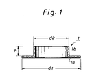
- Fig. 1 is a cross-sectional view illustrating a cutting protection member 1 for use in a pipe lining method according to an embodiment of the present invention.
- the cutting protection member 1 is made of a metal such as stainless steel (SUS) or the like, and is composed of a flange portion 1a and a cylindrical protector portion 1b integrally formed with the inner periphery of the flange portion 1a.
- SUS stainless steel
- the flange portion 1a of the cutting protection member 1 has an outer diameter dl larger than an inner diameter d of a branch pipe 11 (see Fig. 2), later described (d1>d), and is molded into an arcuate shape conformal to the inner wall of a main pipe 10 (see Fig. 2), later described.
- the protector portion 1b formed integrally with the inner periphery of the flange 1a has an outer diameter d2 set slightly smaller than the inner diameter d of the branch pipe 11, and a height set in a range of 10m/m to 50 m/m.
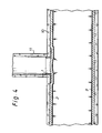
- FIGS. 2 - 6 are cross-sectional views illustrating in order various steps of the pipe lining method according to an embodiment of the present invention.
- the cutting protection member 1 previously illustrated in Fig. 1 is first fitted into a branch pipe opening (a portion of a branch pipe open to a main pipe) from a main pipe 10 and fixed with an arbitrary means (for example, an appropriate adhesive). Specifically, the cutting protection member 1 is attached along the periphery of the branch pipe opening of the main pipe 10 such that the flange portion la is closely contacted to the inner wall of the main pipe 10, and the protector portion 1b is fitted into the branch pipe 11.
- an arbitrary means for example, an appropriate adhesive
- the main pipe is lined using a main pipe liner bag 2, as illustrated in Fig. 3.
- the main pipe liner bag 2 is everted and inserted into the main pipe 10 with a fluid pressure such as an air pressure or the like.
- the main pipe liner bag 2 comprises a tubular resin-absorbent material having its outer peripheral surface covered with a highly air-tight plastic film 3, and an unhardened liquid thermosetting resin impregnated in the tubular resin-absorbent material.
- the tubular resin-absorbent material is made of unwoven fabric such as polyester, polypropylene, acrylic fabric, or the like, and the unhardened liquid hardenable resin impregnated in the tubular resin-absorbent material may be a thermosetting resin such as unsaturated polyester resin, epoxy resin, vinyl ester resin, or the like.
- the plastic film 3 may be molded into a seamless tubular shape by an inflation method, and a material suitable for the plastic film 3 may be selected from polyurethane, polyethylene, nylon, ethylene vinyl alcohol, admer, ionomer, vinyl chloride, and so on.
- the plastic film 3 is applied over the entire outer surface of the tubular resin-absorbent material by thermal welding, bonding or coating.
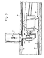
- a cutting robot 12 is introduced into the main pipe 10 for a cutting operation for cutting away the covering portion of the main pipe liner bag 2.
- the cutting robot 12 is hydraulically driven to advance and retract its head 12a in the directions indicated by arrows a, and to rotate the head 12a in the directions indicated by arrows b.
- Pull ropes 13, 14 are connected to the robot 12, and a TV camera 15 is installed on the top of the robot 12.
- the head 12a of the cutting robot 12 is provided with a hydraulic cylinder 16, and a hydraulic motor 17 is supported by a rod 16a of the hydraulic cylinder 16 vertically movable in the directions indicated by arrows c in Fig. 5.
- a cutter 18 having an outer diameter smaller than the inner diameter of the cutting protection member 1 is attached to an output shaft 17a of the hydraulic motor 17.
- the cutter 18 includes a wire brush 18a sandwiched between upper and lower discoidal sanding disks 18b, and a rimer 18c on the top.
- the pull rope 13 or 14 is pulled to move the cutting robot along the main pipe 10 in an appropriate direction in order to place the cutter 18 at a predetermined position. Subsequently, as the hydraulic motor 17 and the cutter 18 are moved upward while the hydraulic motor 17 is being driven to rotate the cutter 18, a portion of the main pipe liner bag 2 covering the branch pipe opening (a portion surrounded by the cutting protection member 1) is cut by the cutter 18.
- the cutting protection member 1 functions as a guide for the cutter 18 as well as functions as a protection member for protecting the inner wall of the branch pipe 11, the main pipe liner bag 2 can be precisely cut away along the branch pipe opening using the cutter 18, thereby making it possible to prevent damages to the inner wall of the branch pipe 11 and the cutter 18 itself.
- the wire brush 18a of the cutter 18 can cut the main pipe liner bag 2 made of a hardened resin but cannot cut the cutting protection member 1 made of a metal, the cutting protection member 1 will never be cut by the cutter 18, whereby the inner wall of the branch pipe 11 and the cutter are more reliably protected by the cutting protection member 1 from damages.
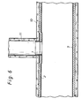
- the branch pipe 11 is open to the main pipe 10 so that they are in communication with each other, as illustrated in Fig. 6.
- the cutting protection member is attached along the periphery of a branch pipe opening of a main pipe before the main pipe is lined using a main pipe liner bag, and subsequently the main pipe is lined using the main pipe liner bag, so that the cutting protection member functions as a guide for the cutter when cutting a portion of the main pipe liner bag covering the branch pipe opening as well as functions as a protection member for protecting the inner wall of the branch pipe, thereby making it possible to precisely cut the main pipe liner bag along the branch pipe opening using the cutter and to prevent the inner wall of the branch pipe and the cutter from damages.
- the wire brush of the cutter can cut the main pipe liner bag made of a hardened resin but cannot cut the cutting protection member made of a metal, the cutting protection member will never be cut by the cutter, whereby the inner wall of the branch pipe and the cutter are more reliably protected by the cutting protection member from damages.
Landscapes
- Engineering & Computer Science (AREA)
- Manufacturing & Machinery (AREA)
- General Engineering & Computer Science (AREA)
- Mechanical Engineering (AREA)
- Lining Or Joining Of Plastics Or The Like (AREA)
- Pipe Accessories (AREA)
- Protection Of Pipes Against Damage, Friction, And Corrosion (AREA)
Applications Claiming Priority (2)
| Application Number | Priority Date | Filing Date | Title |
|---|---|---|---|
| JP10014038A JPH11207821A (ja) | 1998-01-27 | 1998-01-27 | 管ライニング工法 |
| JP1403898 | 1998-01-27 |
Publications (2)
| Publication Number | Publication Date |
|---|---|
| EP0931639A2 true EP0931639A2 (de) | 1999-07-28 |
| EP0931639A3 EP0931639A3 (de) | 2000-01-26 |
Family
ID=11849969
Family Applications (1)
| Application Number | Title | Priority Date | Filing Date |
|---|---|---|---|
| EP99300608A Withdrawn EP0931639A3 (de) | 1998-01-27 | 1999-01-27 | Rohrauskleidungsverfahren |
Country Status (7)
| Country | Link |
|---|---|
| US (1) | US6056017A (de) |
| EP (1) | EP0931639A3 (de) |
| JP (1) | JPH11207821A (de) |
| KR (1) | KR19990068142A (de) |
| AU (1) | AU1427799A (de) |
| CA (1) | CA2260464A1 (de) |
| TW (1) | TW434137B (de) |
Cited By (4)
| Publication number | Priority date | Publication date | Assignee | Title |
|---|---|---|---|---|
| WO2000055539A1 (en) * | 1999-03-18 | 2000-09-21 | Thames Water Utilities Limited | Mains |
| GB2475482B (en) * | 2009-11-18 | 2014-09-10 | Waterflow Group Plc | Method and apparatus for creating apertures in a pipeline |
| CN104608162A (zh) * | 2014-12-30 | 2015-05-13 | 东莞理工学院 | 一种数控卷料振动刀切割设备 |
| EP4119831A1 (de) * | 2021-07-14 | 2023-01-18 | Amex Sanivar AG | Rohrleitungssanierungssystem und verfahren zur sanierung einer rohrleitung |
Families Citing this family (34)
| Publication number | Priority date | Publication date | Assignee | Title |
|---|---|---|---|---|
| FR2767179B1 (fr) * | 1997-08-08 | 1999-09-10 | Coflexip | Systeme multi-outils utilisable pour le raccordement de conduites |
| US6540439B2 (en) | 2000-06-27 | 2003-04-01 | Terre Hill Silo Company | Junction seal between a liner of an underground structure and a penetrating pipe |
| CA2325891A1 (fr) * | 2000-11-14 | 2002-05-14 | Mario Mercier | Rehabilitation par chemisage de conduites d'aqueduc |
| CA2354226A1 (en) | 2001-01-31 | 2002-07-31 | Cal Holland | Robotic apparatus and method for non-destructive maintenance of intersecting conduits |
| JP4615756B2 (ja) * | 2001-04-05 | 2011-01-19 | 積水化学工業株式会社 | 更生管の点検口更生方法 |
| US20040020544A1 (en) * | 2002-04-05 | 2004-02-05 | Takao Kamiyama | Pressure bag and method of lining branch pipe |
| JP4452558B2 (ja) * | 2004-05-28 | 2010-04-21 | 株式会社湘南合成樹脂製作所 | 既設管の更生工法 |
| US7720570B2 (en) * | 2004-10-01 | 2010-05-18 | Redzone Robotics, Inc. | Network architecture for remote robot with interchangeable tools |
| WO2006078873A2 (en) * | 2005-01-18 | 2006-07-27 | Redzone Robotics, Inc. | Autonomous inspector mobile platform |
| US8170715B1 (en) * | 2005-01-25 | 2012-05-01 | Redzone Robotics, Inc. | Methods and devices for automated work in pipes based on impedance control |
| US7270150B2 (en) * | 2005-06-14 | 2007-09-18 | Warren Environmental, Inc. | Method of lining a pipeline |
| US7670086B2 (en) * | 2005-11-23 | 2010-03-02 | Lmk Enterprises, Inc. | Method of repairing a manhole chimney using a stretchable sleeve |
| WO2007127447A2 (en) * | 2006-04-27 | 2007-11-08 | Ina Acquisition Corp. | Reinstatement of an existing connection in a lined conduit |
| WO2008034144A2 (en) * | 2006-09-15 | 2008-03-20 | Redzone Robotics, Inc. | Manhole modeler |
| JP5134400B2 (ja) * | 2008-03-07 | 2013-01-30 | 株式会社湘南合成樹脂製作所 | 管側壁切削装置 |
| US20090289451A1 (en) * | 2008-05-21 | 2009-11-26 | Ina Acquisition Corp. | T-Nut Assembly For Sealing An Existing Connection In A Lined Conduit |
| US8525124B2 (en) * | 2008-11-03 | 2013-09-03 | Redzone Robotics, Inc. | Device for pipe inspection and method of using same |
| US8272406B2 (en) * | 2009-08-07 | 2012-09-25 | Fer-Pal Construction Ltd. | Methods for rehabilitating conduits using structural liners |
| US8820363B2 (en) * | 2010-03-24 | 2014-09-02 | Ina Acquisition Corp. | Wedge type plug and method of plugging a lateral line |
| WO2015161212A1 (en) | 2014-04-17 | 2015-10-22 | Daniel Warren | Large diameter pipe lining and repair |
| WO2016163191A1 (ja) * | 2015-04-07 | 2016-10-13 | 株式会社湘南合成樹脂製作所 | 穿孔装置及び穿孔方法 |
| CN106931274B (zh) * | 2017-04-23 | 2018-08-21 | 诸暨市合纵科技有限公司 | 一种便于安装摄像头的管道机器人 |
| US10386006B2 (en) * | 2017-08-18 | 2019-08-20 | Sanexen Environmental Services Inc. | Method and apparatus for rehabilitation of water conduit with lateral openings |
| JP7240750B2 (ja) * | 2018-05-07 | 2023-03-16 | 株式会社湘南合成樹脂製作所 | 管内ロボット |
| US11079055B2 (en) | 2018-10-30 | 2021-08-03 | Ina Acquisition Corp. | Fitting for connecting a main pipe liner to a branch conduit |
| CA3118286A1 (en) | 2018-10-30 | 2020-05-07 | Ina Acquisition Corp. | Fitting for connecting a main pipe liner to a branch conduit |
| US11391407B2 (en) | 2018-11-30 | 2022-07-19 | Ina Acquisition Corp. | Methods, systems, and apparatus for use in main pipes connected to branch conduit |
| CN112077928B (zh) * | 2020-08-19 | 2022-12-16 | 建湖双湖机械有限公司 | 一种pe波纹管打孔装置及其工作方法 |
| US12123537B2 (en) * | 2021-02-11 | 2024-10-22 | Ina Acquisition Corp. | Mobile system for pipe rehabilitation |
| CN114046394B (zh) * | 2021-11-19 | 2023-06-13 | 长春工业大学 | 一种用于非开挖地下旧注水管道的修复方法 |
| CN114709747B (zh) * | 2022-04-13 | 2023-05-12 | 华北电力大学(保定) | 自适应异形空间电缆管道巡检机器人 |
| CA3199226A1 (en) * | 2022-05-06 | 2023-11-06 | Fer-Pal Construction Ltd. | Apparatus and method for tapping a valve of a host pipe lined with a liner |
| CN115875533B (zh) * | 2023-03-03 | 2023-05-09 | 济南和立新材料有限公司 | 一种内衬管及其修复方法 |
| US20250129876A1 (en) * | 2023-10-23 | 2025-04-24 | BrightAI Corporation | Systems and associated methods for real-time feature detection of an environment |
Family Cites Families (15)
| Publication number | Priority date | Publication date | Assignee | Title |
|---|---|---|---|---|
| US3762028A (en) * | 1972-02-25 | 1973-10-02 | Dow Chemical Co | Joining of plastic/metal foil laminates |
| FR2456280A1 (fr) * | 1979-05-11 | 1980-12-05 | Syndicat Nal Prof Entre Trav D | Raccord de branchement d'un drain sur un collecteur |
| US4893841A (en) * | 1989-04-20 | 1990-01-16 | Bowen William D | Reamer guide for primary sewer line taps |
| JP2554411B2 (ja) * | 1991-05-31 | 1996-11-13 | 株式会社ゲット | 枝管ライニング材及びその製造方法 |
| JP2530553B2 (ja) * | 1993-03-23 | 1996-09-04 | 株式会社湘南合成樹脂製作所 | 枝管ライニング工法 |
| GB9225528D0 (en) * | 1992-12-07 | 1993-01-27 | Insituform Group Ltd | Improvements relating to the lining of pipelines and passageways |
| JPH08426B2 (ja) * | 1993-04-13 | 1996-01-10 | 株式会社湘南合成樹脂製作所 | 管ライニング材とその製造方法及び管路補修工法 |
| JP2528429B2 (ja) * | 1993-08-31 | 1996-08-28 | 株式会社湘南合成樹脂製作所 | 枝管ライニング工法 |
| JP2528430B2 (ja) * | 1993-08-31 | 1996-08-28 | 株式会社湘南合成樹脂製作所 | 枝管ライニング材の製造方法 |
| JP2564092B2 (ja) * | 1993-09-28 | 1996-12-18 | 株式会社湘南合成樹脂製作所 | 枝管ライニング工法 |
| AT403391B (de) * | 1994-03-01 | 1998-01-26 | Klug Kanal Leitungs Und Umwelt | Verfahren zur herstellung dichter einmündungen von hausanschlussrohren und ähnlichen zuflussrohren in abwasserkanäle |
| JP2605220B2 (ja) * | 1994-07-05 | 1997-04-30 | 株式会社湘南合成樹脂製作所 | 枝管ライニング工法 |
| JPH0834055A (ja) * | 1994-07-25 | 1996-02-06 | Shonan Gosei Jushi Seisakusho:Kk | 切削穿孔装置 |
| JP2974132B2 (ja) * | 1997-02-04 | 1999-11-08 | 株式会社湘南合成樹脂製作所 | 管ライニング工法 |
| TW386936B (en) * | 1997-07-18 | 2000-04-11 | Get Inc | Making jig for a branch opening and pipe lining working method for a branch opening |
-
1998
- 1998-01-27 JP JP10014038A patent/JPH11207821A/ja active Pending
-
1999
- 1999-01-26 CA CA002260464A patent/CA2260464A1/en not_active Abandoned
- 1999-01-26 TW TW088101123A patent/TW434137B/zh not_active IP Right Cessation
- 1999-01-26 KR KR1019990002415A patent/KR19990068142A/ko not_active Ceased
- 1999-01-27 EP EP99300608A patent/EP0931639A3/de not_active Withdrawn
- 1999-01-27 US US09/238,275 patent/US6056017A/en not_active Expired - Lifetime
- 1999-01-29 AU AU14277/99A patent/AU1427799A/en not_active Abandoned
Non-Patent Citations (1)
| Title |
|---|
| None |
Cited By (4)
| Publication number | Priority date | Publication date | Assignee | Title |
|---|---|---|---|---|
| WO2000055539A1 (en) * | 1999-03-18 | 2000-09-21 | Thames Water Utilities Limited | Mains |
| GB2475482B (en) * | 2009-11-18 | 2014-09-10 | Waterflow Group Plc | Method and apparatus for creating apertures in a pipeline |
| CN104608162A (zh) * | 2014-12-30 | 2015-05-13 | 东莞理工学院 | 一种数控卷料振动刀切割设备 |
| EP4119831A1 (de) * | 2021-07-14 | 2023-01-18 | Amex Sanivar AG | Rohrleitungssanierungssystem und verfahren zur sanierung einer rohrleitung |
Also Published As
| Publication number | Publication date |
|---|---|
| TW434137B (en) | 2001-05-16 |
| CA2260464A1 (en) | 1999-07-27 |
| EP0931639A3 (de) | 2000-01-26 |
| KR19990068142A (ko) | 1999-08-25 |
| US6056017A (en) | 2000-05-02 |
| JPH11207821A (ja) | 1999-08-03 |
| AU1427799A (en) | 1999-08-19 |
Similar Documents
| Publication | Publication Date | Title |
|---|---|---|
| US6056017A (en) | Pipe lining method | |
| EP0978681B1 (de) | Auskleidung eines Abzweigrohres und Auskleidungsverfahren | |
| EP0620102B1 (de) | Auskleidungsverfahren und Auskleidung eines Abzweigrohres | |
| US5944058A (en) | Branch pipe liner assembly and a pipe lining method | |
| US6085794A (en) | Pipe lining method | |
| US6206993B1 (en) | Method and apparatus for providing a tubular material within a pipeline | |
| EP0938964B1 (de) | Auskleidung eines Abzweigrohres und Auskleidungsverfahren | |
| EP0691507B1 (de) | Verfahren zur Beschichtung einer Abzweigleitung eines unterirdischen Rohres | |
| US6123109A (en) | Branch pipe lining bag and pipe lining method | |
| US6006787A (en) | Branch pipe liner bag and branch pipe lining method | |
| EP0856697B1 (de) | Rohrauskleidungsverfahren | |
| EP0620101B1 (de) | Verfahren und Vorrichtung zur Auskleidung eines Abzweigrohres | |
| EP0620100A2 (de) | Umstülpverfahren für einen Auskleidungsschlauch | |
| EP0891857B1 (de) | Vorrichtung zum Orten des Eintritts einer Abzweigrohrleitung und Rohrauskleidungsverfahren unter Verwendung dieser Vorrichtung | |
| EP0911568B1 (de) | Vorrichtung zur Auskleidung eines Abzweigrohres und Verfahren zur Auskleidung eines Rohres | |
| JP2702099B2 (ja) | 枝管用鍔付スタートライナー及び管ライニング工法 | |
| JP2678148B2 (ja) | 枝管ライニング材及び枝管ライニング工法 | |
| AU7841098A (en) | Device for confirming the position of branch pipe opening and pipe lining method using the device |
Legal Events
| Date | Code | Title | Description |
|---|---|---|---|
| PUAI | Public reference made under article 153(3) epc to a published international application that has entered the european phase |
Free format text: ORIGINAL CODE: 0009012 |
|
| AK | Designated contracting states |
Kind code of ref document: A2 Designated state(s): DE DK FR GB |
|
| AX | Request for extension of the european patent |
Free format text: AL;LT;LV;MK;RO;SI |
|
| PUAL | Search report despatched |
Free format text: ORIGINAL CODE: 0009013 |
|
| AK | Designated contracting states |
Kind code of ref document: A3 Designated state(s): AT BE CH CY DE DK ES FI FR GB GR IE IT LI LU MC NL PT SE |
|
| AX | Request for extension of the european patent |
Free format text: AL;LT;LV;MK;RO;SI |
|
| 17P | Request for examination filed |
Effective date: 20000721 |
|
| AKX | Designation fees paid |
Free format text: DE DK FR GB |
|
| 17Q | First examination report despatched |
Effective date: 20010807 |
|
| STAA | Information on the status of an ep patent application or granted ep patent |
Free format text: STATUS: THE APPLICATION IS DEEMED TO BE WITHDRAWN |
|
| 18D | Application deemed to be withdrawn |
Effective date: 20050628 |