EP4119831A1 - Rohrleitungssanierungssystem und verfahren zur sanierung einer rohrleitung - Google Patents
Rohrleitungssanierungssystem und verfahren zur sanierung einer rohrleitung Download PDFInfo
- Publication number
- EP4119831A1 EP4119831A1 EP22177854.1A EP22177854A EP4119831A1 EP 4119831 A1 EP4119831 A1 EP 4119831A1 EP 22177854 A EP22177854 A EP 22177854A EP 4119831 A1 EP4119831 A1 EP 4119831A1
- Authority
- EP
- European Patent Office
- Prior art keywords
- pipeline
- sleeve
- section
- rehabilitation system
- base plate
- Prior art date
- Legal status (The legal status is an assumption and is not a legal conclusion. Google has not performed a legal analysis and makes no representation as to the accuracy of the status listed.)
- Granted
Links
Images

Classifications
-
- F—MECHANICAL ENGINEERING; LIGHTING; HEATING; WEAPONS; BLASTING
- F16—ENGINEERING ELEMENTS AND UNITS; GENERAL MEASURES FOR PRODUCING AND MAINTAINING EFFECTIVE FUNCTIONING OF MACHINES OR INSTALLATIONS; THERMAL INSULATION IN GENERAL
- F16L—PIPES; JOINTS OR FITTINGS FOR PIPES; SUPPORTS FOR PIPES, CABLES OR PROTECTIVE TUBING; MEANS FOR THERMAL INSULATION IN GENERAL
- F16L55/00—Devices or appurtenances for use in, or in connection with, pipes or pipe systems
- F16L55/16—Devices for covering leaks in pipes or hoses, e.g. hose-menders
- F16L55/162—Devices for covering leaks in pipes or hoses, e.g. hose-menders from inside the pipe
- F16L55/165—Devices for covering leaks in pipes or hoses, e.g. hose-menders from inside the pipe a pipe or flexible liner being inserted in the damaged section
- F16L55/1657—Devices for covering leaks in pipes or hoses, e.g. hose-menders from inside the pipe a pipe or flexible liner being inserted in the damaged section lengths of rigid pipe being inserted
-
- F—MECHANICAL ENGINEERING; LIGHTING; HEATING; WEAPONS; BLASTING
- F16—ENGINEERING ELEMENTS AND UNITS; GENERAL MEASURES FOR PRODUCING AND MAINTAINING EFFECTIVE FUNCTIONING OF MACHINES OR INSTALLATIONS; THERMAL INSULATION IN GENERAL
- F16L—PIPES; JOINTS OR FITTINGS FOR PIPES; SUPPORTS FOR PIPES, CABLES OR PROTECTIVE TUBING; MEANS FOR THERMAL INSULATION IN GENERAL
- F16L41/00—Branching pipes; Joining pipes to walls
- F16L41/08—Joining pipes to walls or pipes, the joined pipe axis being perpendicular to the plane of a wall or to the axis of another pipe
- F16L41/14—Joining pipes to walls or pipes, the joined pipe axis being perpendicular to the plane of a wall or to the axis of another pipe by screwing an intermediate part against the inside or outside of the wall
-
- F—MECHANICAL ENGINEERING; LIGHTING; HEATING; WEAPONS; BLASTING
- F16—ENGINEERING ELEMENTS AND UNITS; GENERAL MEASURES FOR PRODUCING AND MAINTAINING EFFECTIVE FUNCTIONING OF MACHINES OR INSTALLATIONS; THERMAL INSULATION IN GENERAL
- F16L—PIPES; JOINTS OR FITTINGS FOR PIPES; SUPPORTS FOR PIPES, CABLES OR PROTECTIVE TUBING; MEANS FOR THERMAL INSULATION IN GENERAL
- F16L55/00—Devices or appurtenances for use in, or in connection with, pipes or pipe systems
- F16L55/16—Devices for covering leaks in pipes or hoses, e.g. hose-menders
- F16L55/179—Devices for covering leaks in pipes or hoses, e.g. hose-menders specially adapted for bends, branch units, branching pipes or the like
Definitions
- the invention relates to a pipeline rehabilitation system for a pipeline and a method for rehabilitation of a pipeline.
- Digging pipe rehabilitation includes various methods of repairing damaged pipes.
- the insertion of partial liners, also called short liners, pipe lining or pipe line lining is common.
- the pipelines are provided with a renovation lining. This consists of a glass fiber or felt hose impregnated with reaction resin or a plastic hose impregnated with synthetic resin. What the methods have in common is that existing inlets or outlets in the pipelines, such as house connections, are closed off by the rehabilitation lining.
- the US 2020/0132234 A1 discloses a fitting for connecting a branch pipe to a liner installed in a main pipe.
- the fitting has a sleeve portion for receipt within the branch conduit, and is secured by fasteners in the form of teeth extending radially from the outside of the sleeve portion.
- the US 2009/0289451 A1 covers a T-nut assembly for restoring a sealed connection in a lined pipeline.
- the technological background includes one in the US 1,887,423A disclosed flange coupling for a tank.
- the invention is based on the object of creating a functionally and structurally advantageous pipeline rehabilitation system for a pipeline provided with a rehabilitation lining and of demonstrating an improved method for the rehabilitation of a pipeline.
- the solution of the subject part consists in a pipeline rehabilitation system according to claim 1.
- the pipeline rehabilitation system is intended for the rehabilitation of pipelines lined with a hose liner.
- a pipeline has a connection opening in which a house connection arrangement can be fixed.
- the house connection arrangement has an upper part and a lower part.
- the upper part has a base plate and a sleeve section.
- a passageway extends centrally through the sleeve section along its length.
- An internal thread and a chamber with a sealing ring are provided on the inner circumference of the sleeve section.
- the upper part can be plugged through the connection opening with the sleeve section.
- the base plate is designed to rest against an inner wall area of the pipeline.
- the lower part has a sleeve body with an external thread and a radial collar, a seat with a seal being provided between the external thread and the radial collar.
- the pipeline rehabilitation system has been improved in terms of application, function and, in particular, structural components.
- the house connection arrangement of the pipeline rehabilitation system comprises two components with integrated seals.
- the upper part is glued into the old pipe before the renovation liner is pulled through.
- the upper part with the sleeve section is inserted through an existing connection opening or one that is to be produced and glued to the inner wall of the pipeline to be renovated. Effective and durable adhesives are available for bonding.
- the liner After gluing the upper part, the liner is pulled through and installed.
- the liner fully covers the top of the service fitting assembly on the in-pipe side and adheres to the underside of the top. This measure supports the tightness between the tube wall and the sleeve section of the upper part.
- the liner is drilled through and the passage in the upper part is opened.
- the upper part glued into the connection opening and covered by the liner is located.
- Access to the passageway in the sleeve portion of the top is then machined, particularly using a robot.
- the liner is drilled through in the area of the passage.
- the lower part is screwed into the upper part.
- the inside seal is intended to seal the gap between the liner and the screwed-in lower part.
- the seal is arranged between the external thread and the radial collar on or in a seat.
- An advantageous embodiment of the upper part provides that the chamber is arranged in a section between the internal thread and an end of the sleeve body pointing away from the base plate.
- the chamber with the sealing ring is consequently provided on or in the end section of the sleeve body directed away from the interior of the pipeline.
- the seat is advantageously formed circumferentially on the radial collar of the upper part.
- the seat is formed in particular in an annular groove in the annular collar. This configuration ensures an advantageous fit of the sealing ring on the lower part between the external thread and the radial collar.
- the sealing ring is chambered in the seat or the annular groove.
- the surrounding free end of the radial collar is advantageously switched in the direction of the sleeve body. In the installation position of the house connection fitting or the lower part, the circumferential end points in the direction of the hose liner installed in a pipeline.
- the sleeve body has a longitudinal section adjoining the external thread with a sealing surface on the outer periphery intended to cooperate with the seal on the upper part.
- the lower part has at least one tool attachment surface.
- the lower part can be gripped via the tool attachment surfaces with a screwing tool, in particular a robotically guided manipulator, and screwed into the sleeve section for the intended purpose. This is done in a metered manner, with the sleeve body of the lower part being inserted into the sleeve section of the upper part and the external thread of the sleeve body being screwed into the internal thread of the sleeve section.
- the sealing surface of the sleeve body is brought into sealing contact with the sealing ring of the upper part and a wall section of the hose liner is clamped between the upper part and the lower part, with the seal of the lower part being pressed against the hose liner.
- the tool attachment surface is particularly advantageously provided on the inner circumference of the sleeve body.
- a practical embodiment provides that the tool attachment surface is designed by a recess, for example a bore or a groove, on the inner circumference of the sleeve body.
- the base plate has a curved contact surface with which the base plate rests on the inside on the inner circumference of the pipeline to be rehabilitated.
- the base plate is glued to the pipeline to be renovated. This takes place over the entire surface, in particular via the contact surface that is configured to match the inner circumference of the pipeline. Furthermore, bonding takes place in the connection opening in the annular gap between the connection opening and the sleeve section protruding through the connection opening.
- the contact surface of the base plate can have a surface profile that improves the material connection.
- the upper part is first glued into the connection opening and the pipeline.
- the pipe liner is then pulled in.
- the side or surface of the upper part lying in the pipeline is completely covered by the hose liner.
- the lower part is in the upper part screwed in.
- the upper part and the lower part are designed to clamp a wall section of the hose liner between them.
- a system-advantageous configuration provides that the upper part has a locating element.
- the upper part glued in the connection opening can be localized by the locating element.
- Terms such as top and bottom, horizontal and vertical or inside and outside, inside or outside refer to the pipeline 2 and the installation position of the house connection fitting 1 in the pipeline 2.
- Directional information relates to a three-dimensional Cartesian coordinate system around the axes within a pipeline 2 to mark. The origin of the coordinate system is in the center of the pipe.
- the x-axis corresponds to the longitudinal axis of the pipeline 2, the y-axis to the transverse axis of the pipeline and the z-axis to the vertical axis of the pipeline.
- the pipeline rehabilitation system is intended for a pipeline 2 lined with a hose liner 3 .
- the pipeline 2 has a connection opening 4 in which a house connection arrangement 1 can be fixed.
- the house connection arrangement 1 has an upper part 5 and a lower part 6 .
- the upper part 5 has a base plate 7 and a sleeve section 8 with a passage 9.
- a sleeve section 8 In the sleeve section 8 there is an internal thread 10 and a chamber 11 is provided.
- a sealing ring 12 is incorporated in the chamber 11 .
- the chamber 11 is arranged in a section 13 between the internal thread 10 and an end 14 of the sleeve section 8 pointing away from the base plate 7 .
- the upper part 5 can be inserted with the sleeve section 8 through the connection opening 4 in the pipeline 2 , the base plate 7 being designed to rest against an inner wall area 15 of the pipeline 2 .
- the lower part 6 has a sleeve body 16 with an external thread 17 and a radial collar 18 .
- a seat 19 for a seal 20 is arranged in the radial collar 18 below the external thread 17 .
- the seat 19 is formed in an annular groove 21 in the radial collar 18 of the lower part 6 .
- the annular groove 21 runs all the way around the sleeve body 16 on the side of the radial collar 18 facing the sleeve body 16.
- the peripheral free end 22 of the radial collar 18 is switched upwards from its underside 23 in the direction of the sleeve body 16.
- the sleeve body 16 has a longitudinal section 24 adjoining the external thread 17 with a smooth sealing surface 25 on the outer circumference, which is intended to interact with the sealing ring 12 in the upper part 5 .
- the lower part 6 has a tool attachment surface 26 .
- the tool attachment surface 26 is designed and intended to interact with a screwing tool, via which the lower part 6 can be gripped and screwed into the upper part 5 .
- the tool attachment surface 26 is provided on the inner circumference of the sleeve body 16 .
- the base plate 7 has a curved contact surface 27 .
- the contours of the contact surface 27 are matched to the radius of a pipeline 2 or the inner wall region 15 of the pipeline 2 .
- the upper part 5 and the lower part 6 are designed to clamp a wall section 28 of the hose liner 3 between them.
- the pipeline 2 has an existing connection opening 4 or one that is to be produced.
- the upper part 5 is inserted with the sleeve section 8 into the connection opening 4 of the pipeline 2 and glued to the pipeline 2 .
- the base plate 7 comes to rest with the contact surface 27 on an inner wall area 15 of the pipeline 2 surrounding the connection opening 4 .
- the hose liner 3 is pulled into the pipeline 2 and installed.
- the pipeline 2 is completely lined on the inside with the hose liner 3 .
- the underside 29 of the upper part 5 lying in the pipeline 2 is covered by the hose liner 3 .
- an opening 30 is made in the hose liner 3 to the passage 9 in the sleeve section 8 of the upper part 5 . This is done by milling, in particular by machine using a robot. To locate the upper part 5, it can be equipped with a locating element.
- the lower part 6 of the house connection arrangement 1 is screwed into the upper part 5 .
- the sleeve body 16 is guided with the external thread 17 into the sleeve section 8 of the upper part 5 and the external thread 17 of the sleeve body 16 and the internal thread 9 of the sleeve section 8 are screwed into engagement.
- the sealing surface 25 of the sleeve body 16 comes into contact with the sealing ring 12 of the upper part 5 . In this way, a sealing seat is produced in the upper area of the house connection arrangement 1 between the sealing surface 25 of the sleeve body 16 and the sealing ring 12 .
- the pipeline renovation system is installed and the pipeline 2 lined with the hose liner 3 is equipped with a house connection arrangement 1 and prepared for further house connections.
Landscapes
- Engineering & Computer Science (AREA)
- General Engineering & Computer Science (AREA)
- Mechanical Engineering (AREA)
- Pipe Accessories (AREA)
Abstract
Description
- Die Erfindung betrifft ein Rohrleitungssanierungssystem für eine Rohrleitung sowie ein Verfahren zur Sanierung einer Rohrleitung.
- Die grabelose Rohrsanierung umfasst verschiedene Verfahren zur Reparatur beschädigter Rohrleitungen. Gängig ist das Einbringen von partiellen Linern, auch Kurzliner genannt, das Schlauchlining oder auch das Rohrstranglining. Hierbei werden die Rohrleitungen mit einer Sanierungsauskleidung versehen. Diese besteht aus einem mit Reaktionsharz getränkten Glasfaser- oder Filzschlauch oder einem mit Kunstharz getränkten Kunststoffschlauch. Den Verfahren ist gemein, dass in den Rohrleitungen bestehende Zuläufe oder Abgänge, beispielsweise Hausanschlüsse, durch die Sanierungsauskleidung verschlossen werden.
- Sowohl bei der Kurzlinertechnik als auch bei der Inlinertechnik, ebenso wie beim Rohrstranglining müssen die Öffnungen in den Rohrleitungen zu Hausanschlüssen ausgefräst werden. Dies erfolgt üblicherweise ferngesteuert und robotergestützt. Nachdem die Öffnung in die Sanierungsauskleidung hergestellt ist, muss eine zuverlässige und dichte Verbindung der Rohrleitung zu einer Hausanschlussleitung hergestellt werden.
- Die Sanierung von insbesondere Wasser-Hausanschlüssen per Liningverfahren gestaltet sich als problematisch, da die Anbindung der Abgänge durch eine Öffnung im Liner erfolgen muss. Dies erfordert meist die externe Anbringung von Hausanschlusshülsen.
- Durch die
DE 20 2016 106 327 U1 zählt eine Bohrloch-Dichthülse einer Rohrleitungs-Anbohrarmatur und ein entsprechendes System aus einer Rohrleitungs-Anbohrarmatur mit einer solchen Bohrloch-Dichthülse zum Stand der Technik. Solche Anbohrarmaturen werden auf Rohrleitungen von außen aufgesetzt, um eine nachträgliche Anbohrung vornehmen zu können. - Die
US 2020/0132234 A1 offenbart ein Anschlussstück zum Verbinden einer Abzweigleitung mit einer in einem Hauptrohr installierten Auskleidung. Das Anschlussstück weist einen Hülsenabschnitt auf zur Aufnahme in der Abzweigleitung, wobei die Befestigung über Befestigungselemente in Form von Zähnen erfolgt, die sich radial von der Außenseite des Hülsenabschnitts erstrecken. - Die
US 2009/0289451 A1 behandelt eine T-Muttern-Baugruppe zum Wiederherstellen einer abgedichteten Verbindung in einer ausgekleideten Rohrleitung. - Zum technologischen Hintergrund zählt eine in der
US 1,887,423 A offenbarte Flanschkupplung für einen Tank. - Der Erfindung liegt ausgehend vom Stand der Technik die Aufgabe zugrunde, ein funktional und bauteiltechnisch vorteilhaftes Rohrleitungssanierungssystem für eine mit einer Sanierungsauskleidung versehene Rohrleitung zu schaffen sowie ein verbessertes Verfahren zur Sanierung einer Rohrleitung aufzuzeigen.
- Die Lösung des gegenständlichen Teils besteht in einem Rohrleitungssanierungssystem gemäß Anspruch 1.
- Der verfahrensmäßige Teil der Aufgabe wird durch ein Verfahren nach Anspruch 10 gelöst.
- Vorteilhafte Ausgestaltungen und Weiterbildungen der Erfindung sind Gegenstand der abhängigen Ansprüche.
- Ausgestaltungen und Modifikationen von Merkmalen des Rohrleitungssanierungssystems, der Bauteile und der Bauteilanordnungen, ebenso wie der Hausanschlussanordnung des Rohrleitungssanierungssystems, welche einzeln oder in Kombination die Erfindung technisch vorteilhaft ausgestalten, ergeben sich aus der Beschreibung und den beigefügten Zeichnungen.
- Das Rohrleitungssanierungssystem ist für die Sanierung von Rohrleitungen bestimmt, die mit einem Schlauchliner ausgekleidet sind. Eine solche Rohrleitung weist eine Anschlussöffnung auf, in welche eine Hausanschlussanordnung festlegbar ist. Die Hausanschlussanordnung weist ein Oberteil und ein Unterteil auf.
- Erfindungsgemäß weist das Oberteil eine Grundplatte und einen Hülsenabschnitt auf. Zentrisch durch den Hülsenabschnitt erstreckt sich über dessen Länge ein Durchgang. Am Innenumfang des Hülsenabschnitts ist ein Innengewinde sowie eine Kammer mit einem Dichtring vorgesehen. Das Oberteil ist mit dem Hülsenabschnitt durch die Anschlussöffnung steckbar. Die Grundplatte ist zur Anlage an einen Innenwandbereich der Rohrleitung ausgebildet. Das Unterteil weist einen Hülsenkörper mit einem Außengewinde sowie einem Radialkragen auf, wobei zwischen dem Außengewinde und dem Radialkragen ein Sitz mit einer Dichtung vorgesehen ist.
- Das Rohrleitungssanierungssystem ist anwendungstechnisch, funktional und insbesondere bauteiltechnisch verbessert. Die Hausanschlussanordnung des Rohrleitungssanierungssystems umfasst zwei Bauteile mit integrierten Dichtungen. Das Oberteil wird vor dem Durchzug des Sanierungsliners in das Altrohr eingeklebt. Hierzu wird das Oberteil mit dem Hülsenabschnitt durch eine vorhandene oder eine herzustellende Anschlussöffnung gesteckt und mit der Innenwand der zu sanierenden Rohrleitung verklebt. Für die Verklebung stehen wirksame und langlebige Klebstoffe zur Verfügung.
- Nach dem Verkleben des Oberteils wird der Liner durchgezogen und installiert. Der Liner deckt das Oberteil der Hausanschlussanordnung auf der innerhalb der Rohrleitung liegenden Seite vollständig ab und haftet an der Unterseite des Oberteils. Diese Maßnahme unterstützt die Dichtheit zwischen der Rohrwand und dem Hülsenabschnitt des Oberteils.
- Im nächsten Schritt wird der Liner durchbohrt und der Durchgang im Oberteil geöffnet. Hierzu wird das in der Anschlussöffnung eingeklebte und vom Liner abgedeckte Oberteil lokalisiert. Der Zugang zum Durchgang im Hülsenabschnitt des Oberteils wird dann maschinell, insbesondere unter Verwendung eines Roboters, hergestellt. Hierzu wird der Liner im Bereich des Durchgangs durchbohrt. Danach wird das Unterteil in das Oberteil geschraubt. Um den Spalt zwischen Liner und dem eingeschraubten Unterteil abzudichten, ist die innenseitige Dichtung vorgesehen. Die Dichtung ist zwischen dem Außengewinde und dem Radialkragen an bzw. in einem Sitz angeordnet.
- Eine vorteilhafte Ausgestaltung des Oberteils sieht vor, dass die Kammer in einem Abschnitt zwischen dem Innengewinde und einem von der Grundplatte weg gerichteten Ende des Hülsenkörpers angeordnet ist. Die Kammer mit dem Dichtring ist folglich am bzw. im vom Inneren der Rohrleitung weg gerichteten Endabschnitt des Hülsenkörpers vorgesehen.
- Weiterhin vorteilhaft ist der Sitz umlaufend am Radialkragen des Oberteils ausgebildet. Der Sitz ist insbesondere in einer Ringnut im Ringkragen ausgebildet. Diese Ausgestaltung gewährleistet einen vorteilhaften Sitz des Dichtrings am Unterteil zwischen dem Außengewinde und dem Radialkragen. Der Dichtring ist in dem Sitz bzw. der Ringnut gekammert. Vorteilhaft ist das umlaufende freie Ende des Radialkragens in Richtung zum Hülsenkörper umgestellt. In der Einbaulage der Hausanschlussarmatur bzw. des Unterteils weist das umlaufende Ende in Richtung zum in einer Rohrleitung installierten Schlauchliner.
- Eine für die Praxis besonders vorteilhafte Ausgestaltung sieht vor, dass der Hülsenkörper einen sich an das Außengewinde anschließenden Längenabschnitt aufweist mit einer Dichtfläche am Außenumfang, die dazu bestimmt ist, mit der Dichtung am Oberteil zusammenzuwirken.
- Eine weiterhin vorteilhafte Ausgestaltung sieht vor, dass das Unterteil zumindest eine Werkzeugansatzfläche aufweist. Das Unterteil kann über die Werkzeugansatzflächen mit einem Schraubwerkzeug, insbesondere einem robotisch geführten Manipulator, ergriffen und zweckgerichtet in den Hülsenabschnitt eingeschraubt werden. Dies erfolgt dosiert, wobei der Hülsenkörper des Unterteils in den Hülsenabschnitt des Oberteils eingeführt und das Außengewinde des Hülsenkörpers in das Innengewinde des Hülsenabschnitts eingeschraubt wird. Hierbei wird die Dichtfläche des Hülsenkörpers mit dem Dichtring des Oberteils in dichtende Anlage gebracht sowie ein Wandabschnitt des Schlauchliners zwischen dem Oberteil und dem Unterteil eingespannt, wobei die Dichtung des Unterteils gegen den Schlauchliner gepresst wird.
- Besonders vorteilhaft ist die Werkzeugansatzfläche am Innenumfang des Hülsenkörpers vorgesehen. Eine praktische Ausgestaltung sieht vor, dass die Werkzeugansatzfläche durch eine Ausnehmung, beispielsweise eine Bohrung oder eine Nut, am Innenumfang des Hülsenkörpers ausgestaltet ist.
- Die Grundplatte weist eine gekrümmt ausgebildete Anlagefläche auf, mit welcher die Grundplatte innenseitig am Innenumfang der zu sanierenden Rohrleitung anliegt. Die Grundplatte wird mit der zu sanierenden Rohrleitung verklebt. Dies erfolgt vollflächig, insbesondere über die konfigurativ auf den Innenumfang der Rohrleitung abgestimmte Anlagefläche. Weiterhin erfolgt eine Verklebung in der Anschlussöffnung in dem Ringspalt zwischen der Anschlussöffnung und dem durch die Anschlussöffnung ragenden Hülsenabschnitt.
- Die Anlagefläche der Grundplatte kann eine die stoffschlüssige Fügung verbessernde Oberflächenprofilierung aufweisen.
- Das Oberteil wird zunächst in die Anschlussöffnung und die Rohrleitung eingeklebt. Anschließend wird der Schlauchliner eingezogen. Hierbei wird die in der Rohrleitung liegende Seite bzw. Fläche des Oberteils vom Schlauchliner vollständig abgedeckt. Nach dem Öffnen der Durchgangsöffnung wird das Unterteil in das Oberteil eingeschraubt. Das Oberteil und das Unterteil sind dazu ausgebildet, zwischen sich einen Wandabschnitt des Schlauchliners einzuspannen.
- Eine systemvorteilhafte Ausgestaltung sieht vor, dass das Oberteil ein Ortungselement aufweist. Durch das Ortungselement kann das in der Anschlussöffnung verklebte Oberteil lokalisiert werden. Es erfolgt eine Positionierung für das Ansetzen des Fräswerkzeugs zum Herstellen der Öffnung im Schlauchliner und dem Anschluss an die Anschlussöffnung.
- Das Verfahren zur Sanierung einer Rohrleitung charakterisiert sich durch folgende Schritte:
- Lokalisieren einer vorhandenen Anschlussöffnung oder Herstellen einer Anschlussöffnung in der Rohrleitung;
- Bereitstellen eines Oberteils einer Hausanschlussanordnung, welches eine Grundplatte und einen Hülsenabschnitt aufweist und im Hülsenabschnitt eine Innengewinde sowie eine Kammer mit einem Dichtring vorgesehen ist;
- Einbringen des Oberteils unter Applikation eines Klebstoffs, wobei das Oberteil mit dem Hülsenabschnitt durch die Anschlussöffnung gesteckt und die Grundplatte mit einer Anlagefläche an einem die Anschlussöffnung umgebenden Innenwandbereich zur Anlage gebracht und das Oberteil mit der Rohrleitung verklebt wird;
- Einbringen eines Schlauchliners in die Rohrleitung und Auskleiden der Rohrleitung mit dem Schlauchliner, wobei eine in der Rohrleitung liegende Seite des Oberteils vom Schlauchliner abgedeckt wird;
- Herstellen einer Öffnung zum Durchgang im Hülsenabschnitt des Oberteils;
- Bereitstellen eines Unterteils der Hausanschlussanordnung, welches einen Hülsenkörper mit einem Außengewinde sowie einem Radialkragen aufweist und zwischen dem Außengewinde und dem Radialkragen ein Sitz mit einer Dichtung vorgesehen ist;
- Einschrauben des Unterteils in das Oberteil, wobei
- der Hülsenkörper des Unterteils in den Hülsenabschnitt des Oberteils geführt und das Außengewinde des Hülsenkörpers und das Innengewinde des Hülsenabschnitts in Eingriff gebracht werden sowie
- eine Dichtfläche des Hülsenkörpers mit dem Dichtring des Oberteils zur Anlage gelangt,
- ein Wandabschnitt des Schlauchliners zwischen dem Oberteil und dem Unterteil eingespannt wird und
- die Dichtung des Unterteils gegen den Schlauchliner gepresst wird.
- Die Erfindung ist nachfolgend anhand von in den Zeichnungen dargestellten Ausführungsbeispielen ergänzend beschrieben. Es zeigen:
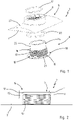
- Figur 1
- eine Hausanschlussanordnung eines erfindungsgemäßen Rohrleitungssanierungssystems in einer perspektivischen Explosionsdarstellung;
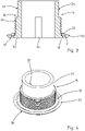
- Figur 2
- einen Schnitt durch das Oberteil der Hausanschlussanordnung;
- Figur 3
- einen Schnitt durch das Unterteil der Hausanschlussanordnung;
- Figur 4
- das Unterteil in einer perspektivischen Ansicht;
- Figur 5
- das Oberteil und das Unterteil der Hausanschlussanordnung in einer schematisierten Schnittdarstellung;
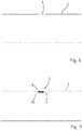
- Figur 6
- einen Ausschnitt einer zu sanierenden Rohrleitung;
- Figur 7
- die Rohrleitung mit einem in einer Anschlussöffnung eingeklebten Oberteil der Hausanschlussanordnung;
- Figur 8
- die Darstellung entsprechend der
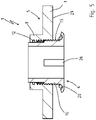
Figur 7 mit eingezogenem Schlauchliner und - Figur 9
- die Darstellung der Rohrleitung mit montierter Hausanschlussanordnung in einer Schnittdarstellung.
- Anhand der
Figuren 1 bis 9 ist ein erfindungsgemäßes Rohrleitungssanierungssystem und die dazugehörige Hausanschlussanordnung 1 sowie ein Verfahren zur Sanierung einer Rohrleitung 2 beschrieben. - In den Figuren werden für gleiche oder funktional einander entsprechende Bauteile bzw. Bauteilkomponenten die gleich Bezugszeichen verwendet.
- Begriff wie oben und unten, horizontal und vertikal oder Innenseite und Außenseite, innenseitig oder außenseitig beziehen sich auf die Rohrleitung 2 und die Einbaulage der Hausanschlussarmatur 1 in der Rohrleitung 2. Richtungsangaben beziehen sich auf ein dreidimensionales kartesisches Koordinatensystem, um die Achsen innerhalb einer Rohrleitung 2 zu kennzeichnen. Der Ursprung des Koordinatensystems liegt im Rohrleitungsmittelpunkt. Die x-Achse entspricht der Längsachse der Rohrleitung 2, die y-Achse der Rohrleitungsquerachse und die z-Achse der Rohrleitungshochachse.
- Das Rohrleitungssanierungssystem ist bestimmt für eine Rohrleitung 2, die mit einem Schlauchliner 3 ausgekleidet ist. Die Rohrleitung 2 weist eine Anschlussöffnung 4 auf, in welcher eine Hausanschlussanordnung 1 festlegbar ist.
- Die Hausanschlussanordnung 1 weist ein Oberteil 5 und ein Unterteil 6 auf.
- Das Oberteil 5 besitzt eine Grundplatte 7 und einen Hülsenabschnitt 8 mit einem Durchgang 9. Im Hülsenabschnitt 8 ist ein Innengewinde 10 sowie eine Kammer 11 vorgesehen. In der Kammer 11 ist ein Dichtring 12 eingegliedert. Die Kammer 11 ist in einem Abschnitt 13 zwischen dem Innengewinde 10 und einem von der Grundplatte 7 weg gerichteten Ende 14 des Hülsenabschnitts 8 angeordnet.
- Das Oberteil 5 ist mit dem Hülsenabschnitt 8 durch die Anschlussöffnung 4 in der Rohrleitung 2 steckbar, wobei die Grundplatte 7 zur Anlage an einen Innenwandbereich 15 der Rohrleitung 2 ausgebildet ist.
- Das Unterteil 6 weist einen Hülsenkörper 16 mit einem Außengewinde 17 sowie einen Radialkragen 18 auf. Unterhalb des Außengewindes 17 ist im Radialkragen 18 ein Sitz 19 für eine Dichtung 20 angeordnet. Der Sitz 19 ist in einer Ringnut 21 im Radialkragen 18 des Unterteils 6 ausgebildet. Die Ringnut 21 ist umlaufend um den Hülsenkörper 16 geführt auf der zum Hülsenkörper 16 gerichteten Seite des Radialkragens 18. Das umlaufende freie Ende 22 des Radialkragens 18 ist von dessen Unterseite 23 nach oben umgestellt in Richtung zum Hülsenkörper 16.
- Der Hülsenkörper 16 weist einen sich an das Außengewinde 17 anschließenden Längenabschnitt 24 auf mit einer glatten Dichtfläche 25 am Außenumfang, die dazu bestimmt ist, mit dem Dichtring 12 im Oberteil 5 zusammenzuwirken.
- Insbesondere in der
Figur 3 erkennt man, dass das Unterteil 6 eine Werkzeugansatzfläche 26 aufweist. Die Werkzeugansatzfläche 26 ist dazu ausgebildet und bestimmt, mit einem Schraubwerkzeug zusammenzuwirken, über welches das Unterteil 6 ergriffen und in das Oberteil 5 eingeschraubt werden kann. Die Werkzeugansatzfläche 26 ist am Innenumfang des Hülsenkörpers 16 vorgesehen. - Die Grundplatte 7 weist eine gekrümmt ausgebildete Anlagefläche 27 auf. Die Anlagefläche 27 ist auf den Radius einer Rohrleitung 2 bzw. den Innenwandbereich 15 der Rohrleitung 2 konturenmäßig abgestimmt.
- Das Oberteil 5 und das Unterteil 6 sind dazu ausgebildet, zwischen sich einen Wandabschnitt 28 des Schlauchliners 3 einzuspannen.
- Anhand der
Figuren 6 bis 9 ist der Ablauf der Sanierung einer Rohrleitung 2 nochmals erläutert. Die Rohrleitung 2 weist eine vorhandene oder eine herzustellende Anschlussöffnung 4 auf. Das Oberteil 5 wird mit dem Hülsenabschnitt 8 in die Anschlussöffnung 4 der Rohrleitung 2 gesteckt und mit der Rohrleitung 2 verklebt. Hierbei gelangt die Grundplatte 7 mit der Anlagefläche 27 an einem die Anschlussöffnung 4 umgebenden Innenwandbereich 15 der Rohrleitung 2 zur Anlage. - Danach wird der Schlauchliner 3 in die Rohrleitung 2 eingezogen und installiert. Hierbei wird die Rohrleitung 2 innenseitig vollständig mit dem Schlauchliner 3 ausgekleidet. Die in der Rohrleitung 2 liegende Unterseite 29 des Oberteils 5 wird vom Schlauchliner 3 abgedeckt.
- Nach Installation des Schlauchliners 3 wird eine Öffnung 30 im Schlauchliner 3 zum Durchgang 9 im Hülsenabschnitt 8 des Oberteils 5 hergestellt. Dies erfolgt frästechnisch, insbesondere maschinell unter Nutzung eines Roboters. Zur Ortung des Oberteils 5 kann dieses mit einem Ortungselement ausgerüstet sein.
- Als nächstes wird das Unterteil 6 der Hausanschlussanordnung 1 in das Oberteil 5 eingeschraubt. Hierzu wird der Hülsenkörper 16 mit dem Außengewinde 17 in den Hülsenabschnitt 8 des Oberteils 5 geführt und das Außengewinde 17 des Hülsenkörpers 16 und das Innengewinde 9 des Hülsenabschnitts 8 schraubtechnisch in Eingriff gebracht. Beim Einschrauben gelangt die Dichtfläche 25 des Hülsenkörpers 16 mit dem Dichtring 12 des Oberteils 5 in Anlage. Auf diese Weise wird ein Dichtsitz im oberen Bereich der Hausanschlussanordnung 1 zwischen der Dichtfläche 25 des Hülsenkörpers 16 und dem Dichtring 12 hergestellt. Bei der Schraubbewegung wird ein Wandabschnitt 28 des Schlauchliners 3 zwischen dem Oberteil 5 und dem Unterteil 6 eingespannt und die Dichtung 20 im Unterteil 6 gegen den Schlauchliner 3 gepresst. Auf diese Weise wird der Spalt zwischen dem Schlauchliner 3 und dem Unterteil 6 abgedichtet.
- Das Rohrleitungssanierungssystem ist installiert und die mit dem Schlauchliner 3 ausgekleidete Rohrleitung 2 mit einer Hausanschlussanordnung 1 ausgerüstet und für den weiteren Hausanschluss vorbereitet.
-
- 1 -
- Hausanschlussanordnung
- 2 -
- Rohrleitung
- 3 -
- Schlauchliner
- 4 -
- Anschlussöffnung
- 5 -
- Oberteil
- 6 -
- Unterteil
- 7 -
- Grundplatte
- 8 -
- Hülsenabschnitt
- 9 -
- Durchgang
- 10 -
- Innengewinde
- 11 -
- Kammer
- 12 -
- Dichtring
- 13 -
- Abschnitt
- 14 -
- Ende v. 8
- 15 -
- Innenwandbereich
- 16 -
- Hülsenkörper
- 17 -
- Außengewinde
- 18 -
- Radialkragen
- 19 -
- Sitz
- 20 -
- Dichtung
- 21 -
- Ringnut
- 22 -
- Ende v. 18
- 23 -
- Unterseite
- 24 -
- Längenabschnitt
- 25 -
- Dichtfläche
- 26 -
- Werkzeugansatzfläche
- 27 -
- Anlagefläche
- 28 -
- Wandabschnitt
- 29 -
- Unterseite v. 5
- 30 -
- Öffnung
Claims (10)
- Rohrleitungssanierungssystem für eine Rohrleitung (2), die mit einem Schlauchliner (3) ausgekleidet ist und die Rohrleitung (2) eine Anschlussöffnung (4) aufweist, in welcher eine Hausanschlussanordnung (1) festlegbar ist, wobei die Hausanschlussanordnung (1) ein Oberteil (5) und ein Unterteil (6) aufweist, dadurch gekennzeichnet, dass das Oberteil (5) eine Grundplatte (7) und einen Hülsenabschnitt (8) aufweist, wobei im Hülsenabschnitt (8) ein Innengewinde (10) sowie eine Kammer (11) mit einem Dichtring (12) vorgesehen ist, wobei das Oberteil (5) mit dem Hülsenabschnitt (8) durch die Anschlussöffnung (4) steckbar und die Grundplatte (7) zur Anlage an einen Innenwandbereich (15) der Rohrleitung (2) ausgebildet ist und das Unterteil (6) einen Hülsenkörper (16) mit einem Außengewinde (17) sowie einen Radialkragen (18) aufweist, wobei zwischen dem Außengewinde (17) und dem Radialkragen (18) ein Sitz (19) mit einer Dichtung (20) vorgesehen ist.
- Rohrleitungssanierungssystem nach Anspruch 1, dadurch gekennzeichnet, dass die Kammer (11) in einem Abschnitt (13) zwischen dem Innengewinde (10) und einem von der Grundplatte (7) weg gerichteten Ende (14) des Hülsenabschnitts (8) angeordnet ist.
- Rohrleitungssanierungssystem nach Anspruch 1 oder 2, dadurch gekennzeichnet, dass der Sitz (19) durch eine umlaufende Ringnut (21) im Radialkragen (18) ausgebildet ist.
- Rohrleitungssanierungssystem nach einem der Ansprüche 1 bis 3, dadurch gekennzeichnet, dass der Hülsenkörper (16) einen sich an das Außengewinde (17) anschließenden Längenabschnitt (24) aufweist mit einer Dichtfläche (25) am Außenumfang, die dazu bestimmt ist, mit dem Dichtring (12) im Oberteil (5) zusammenzuwirken.
- Rohrleitungssanierungssystem nach einem der Ansprüche 1 bis 4, dadurch gekennzeichnet, dass das Unterteil (6) zumindest eine Werkzeugansatzfläche (26) aufweist.
- Rohrleitungssanierungssystem nach Anspruch 5, dadurch gekennzeichnet, dass die Werkzeugansatzfläche (26) am Innenumfang des Hülsenkörpers (16) vorgesehen ist.
- Rohrleitungssanierungssystem nach einem der Ansprüche 1 bis 6, dadurch gekennzeichnet, dass die Grundplatte (7) eine gekrümmt ausgebildete Anlagefläche (27) aufweist.
- Rohrleitungssanierungssystem nach einem der Ansprüche 1 bis 7, dadurch gekennzeichnet, dass das Oberteil (5) und das Unterteil (6) dazu ausgebildet sind, zwischen sich einen Wandabschnitt (28) des Schlauchliners (3) einzuspannen.
- Rohrleitungssanierungssystem nach einem der Ansprüche 1 bis 8, dadurch gekennzeichnet, dass das Oberteil (5) ein Ortungselement aufweist.
- Verfahren zur Sanierung einer Rohrleitung (2) mit folgenden Schritten:- Lokalisieren einer vorhandenen Anschlussöffnung (4) oder Herstellen einer Anschlussöffnung (4) in der Rohrleitung (2);- Bereitstellen eines Oberteils (5) einer Hausanschlussanordnung (1), welches eine Grundplatte (7) und einen Hülsenabschnitt (8) aufweist und im Hülsenabschnitt (8) ein Innengewinde (10) sowie eine Kammer (11) mit einem Dichtring (12) vorgesehen ist;- Einbringen des Oberteils (5) unter Applikation eines Klebstoffs, wobei das Oberteil (5) mit dem Hülsenabschnitt (8) durch die Anschlussöffnung (4) gesteckt und die Grundplatte (7) mit einer Anlagefläche (27) an einem die Anschlussöffnung (4) umgebenden Innenwandbereich (15) zur Anlage gebracht und das Oberteil (5) mit der Rohrleitung (2) verklebt wird;- Einbringen eines Schlauchliners (3) in die Rohrleitung (2) und Auskleiden der Rohrleitung (2) mit dem Schlauchliner (3), wobei eine in der Rohrleitung (2) liegende Unterseite (29) des Oberteils (5) vom Schlauchliner (3) abgedeckt wird;- Herstellen einer Öffnung (30) zum Durchgang (9) im Hülsenabschnitt (8) des Oberteils (5);- Bereitstellen eines Unterteils (6) der Hausanschlussanordnung (1), welches einen Hülsenkörper (16) mit einem Außengewinde (17) sowie einem Radialkragen (18) aufweist und zwischen dem Außengewinde (17) und dem Radialkragen (18) ein Sitz (19) mit einer Dichtung (20) vorgesehen ist;- Einschrauben des Unterteils (6) in das Oberteil (5), wobei- der Hülsenkörper (16) des Unterteils (6) in den Hülsenabschnitt (8) des Oberteils (5) geführt und das Außengewinde (17) des Hülsenkörpers (16) und das Innengewinde (10) des Hülsenabschnitts (8) in Eingriff gebracht werden sowie- eine Dichtfläche (25) des Hülsenkörpers (16) mit einem Dichtring (12) des Oberteils (5) zur Anlage gelangt,- ein Wandabschnitt (28) des Schlauchliners (3) zwischen dem Oberteil (5) und dem Unterteil (6) eingespannt wird und- die Dichtung (20) des Unterteils (6) gegen den Schlauchliner (3) gepresst wird.
Applications Claiming Priority (1)
| Application Number | Priority Date | Filing Date | Title |
|---|---|---|---|
| DE102021118206.9A DE102021118206B3 (de) | 2021-07-14 | 2021-07-14 | Rohrleitungssanierungssystem und Verfahren zur Sanierung einer Rohrleitung |
Publications (3)
| Publication Number | Publication Date |
|---|---|
| EP4119831A1 true EP4119831A1 (de) | 2023-01-18 |
| EP4119831C0 EP4119831C0 (de) | 2024-03-20 |
| EP4119831B1 EP4119831B1 (de) | 2024-03-20 |
Family
ID=81256439
Family Applications (1)
| Application Number | Title | Priority Date | Filing Date |
|---|---|---|---|
| EP22177854.1A Active EP4119831B1 (de) | 2021-07-14 | 2022-06-08 | Rohrleitungssanierungssystem und verfahren zur sanierung einer rohrleitung |
Country Status (4)
| Country | Link |
|---|---|
| EP (1) | EP4119831B1 (de) |
| DE (1) | DE102021118206B3 (de) |
| ES (1) | ES2981918T3 (de) |
| PL (1) | PL4119831T3 (de) |
Citations (7)
| Publication number | Priority date | Publication date | Assignee | Title |
|---|---|---|---|---|
| US1887423A (en) | 1929-01-02 | 1932-11-08 | Arthur L Parker | Tank flange coupling |
| EP0795712A1 (de) * | 1996-03-13 | 1997-09-17 | PT-Poly-Tec GmbH Vertrieb und Herstellung von Dichtungssystemen | Anschlussvorrichtung |
| EP0931639A2 (de) * | 1998-01-27 | 1999-07-28 | Shonan Gosei - Jushi Seisakusho K.K. | Rohrauskleidungsverfahren |
| US20090289451A1 (en) | 2008-05-21 | 2009-11-26 | Ina Acquisition Corp. | T-Nut Assembly For Sealing An Existing Connection In A Lined Conduit |
| DE202016106327U1 (de) | 2016-11-11 | 2016-11-29 | Hawle Armaturen Gmbh | Bohrloch-Dichthülse einer Rohrleitungs-Anbohrarmatur |
| US20200132234A1 (en) | 2018-10-30 | 2020-04-30 | Ina Acquistion Corp. | Fitting for connecting a main pipe liner to a branch conduit |
| DE102019110315A1 (de) * | 2019-04-18 | 2020-10-22 | Amex Sanivar Ag | Hausanschlussanordnung |
-
2021
- 2021-07-14 DE DE102021118206.9A patent/DE102021118206B3/de not_active Expired - Fee Related
-
2022
- 2022-06-08 EP EP22177854.1A patent/EP4119831B1/de active Active
- 2022-06-08 ES ES22177854T patent/ES2981918T3/es active Active
- 2022-06-08 PL PL22177854.1T patent/PL4119831T3/pl unknown
Patent Citations (7)
| Publication number | Priority date | Publication date | Assignee | Title |
|---|---|---|---|---|
| US1887423A (en) | 1929-01-02 | 1932-11-08 | Arthur L Parker | Tank flange coupling |
| EP0795712A1 (de) * | 1996-03-13 | 1997-09-17 | PT-Poly-Tec GmbH Vertrieb und Herstellung von Dichtungssystemen | Anschlussvorrichtung |
| EP0931639A2 (de) * | 1998-01-27 | 1999-07-28 | Shonan Gosei - Jushi Seisakusho K.K. | Rohrauskleidungsverfahren |
| US20090289451A1 (en) | 2008-05-21 | 2009-11-26 | Ina Acquisition Corp. | T-Nut Assembly For Sealing An Existing Connection In A Lined Conduit |
| DE202016106327U1 (de) | 2016-11-11 | 2016-11-29 | Hawle Armaturen Gmbh | Bohrloch-Dichthülse einer Rohrleitungs-Anbohrarmatur |
| US20200132234A1 (en) | 2018-10-30 | 2020-04-30 | Ina Acquistion Corp. | Fitting for connecting a main pipe liner to a branch conduit |
| DE102019110315A1 (de) * | 2019-04-18 | 2020-10-22 | Amex Sanivar Ag | Hausanschlussanordnung |
Also Published As
| Publication number | Publication date |
|---|---|
| EP4119831C0 (de) | 2024-03-20 |
| PL4119831T3 (pl) | 2024-08-19 |
| ES2981918T3 (es) | 2024-10-11 |
| EP4119831B1 (de) | 2024-03-20 |
| DE102021118206B3 (de) | 2022-05-12 |
Similar Documents
| Publication | Publication Date | Title |
|---|---|---|
| DE19609257C2 (de) | Rohrverbindung | |
| DE69911464T2 (de) | Rohrverbindung | |
| DE69102246T2 (de) | Kupplung. | |
| DE102021118206B3 (de) | Rohrleitungssanierungssystem und Verfahren zur Sanierung einer Rohrleitung | |
| DE69422416T2 (de) | Verfahren zur wiederbeschichtung einer abzweigeleitung | |
| EP3376087B1 (de) | Verschraubbarer abzweig für ein unebenheiten aufweisendes kanalrohr | |
| EP3784947B1 (de) | Rohranschlusssystem und verfahren zur herstellung eines rohranschlusses | |
| DE202021103778U1 (de) | Rohrleitungssanierungssystem | |
| DE19504139C2 (de) | Verfahren zur Abdichtung des Überganges zwischen einer Anschlußleitung und PE-Rohren und Anschlußdichtung | |
| EP1334344B1 (de) | Einrichtung zum prüfen auf dichtigkeit einer dichtanordnung von rohren oder schachtbauwerken | |
| DE102019110305B4 (de) | Hausanschlussbuchse und Hausanschlussanordnung | |
| DE7425585U (de) | Rohr mit flanschverbindungsvorrichtung | |
| AT525110A2 (de) | Bohrlochdichthülse für eine Anbohrarmatur und Verfahren zum Abdichten eines Rohres | |
| DE102019110315B4 (de) | Hausanschlussanordnung | |
| DE19633015A1 (de) | Vorrichtung und Verfahren zum Erstellen von Rohrleitungsabzweigen | |
| AT508734B1 (de) | Vorrichtung zur sanierung einer hausanschlussleitung | |
| DE102020134023B4 (de) | Manschettenanschlussvorrichtung, Herstellungsverfahren und Verfahren zur Einbindung oder Sanierung von Anschlüssen | |
| EP3382253B1 (de) | Gasdichte kunststoff-rohrabzweigung | |
| DE202006001226U1 (de) | Anschlussstutzen für einen Abwasser-Hauptkanal | |
| DE4039353C1 (en) | Closing of damaged plastics pipe - involves plug screwed into side of pipe from housing fitted on outside | |
| EP0677690A1 (de) | Muffenspiegeldichtung | |
| DE4243460C1 (de) | Gasrohrsanierungsanordnung | |
| DE10231034B4 (de) | Rohrverbindungselement | |
| EP0550860A1 (de) | Dichtungsanordnung | |
| DE3804896A1 (de) | Vorrichtung und verfahren zum befestigen eines schlauches aus elastischem material im anschlussloch einer versorgungsleitung |
Legal Events
| Date | Code | Title | Description |
|---|---|---|---|
| PUAI | Public reference made under article 153(3) epc to a published international application that has entered the european phase |
Free format text: ORIGINAL CODE: 0009012 |
|
| STAA | Information on the status of an ep patent application or granted ep patent |
Free format text: STATUS: THE APPLICATION HAS BEEN PUBLISHED |
|
| AK | Designated contracting states |
Kind code of ref document: A1 Designated state(s): AL AT BE BG CH CY CZ DE DK EE ES FI FR GB GR HR HU IE IS IT LI LT LU LV MC MK MT NL NO PL PT RO RS SE SI SK SM TR |
|
| STAA | Information on the status of an ep patent application or granted ep patent |
Free format text: STATUS: REQUEST FOR EXAMINATION WAS MADE |
|
| 17P | Request for examination filed |
Effective date: 20230627 |
|
| GRAP | Despatch of communication of intention to grant a patent |
Free format text: ORIGINAL CODE: EPIDOSNIGR1 |
|
| STAA | Information on the status of an ep patent application or granted ep patent |
Free format text: STATUS: GRANT OF PATENT IS INTENDED |
|
| RIC1 | Information provided on ipc code assigned before grant |
Ipc: F16L 55/165 20060101ALI20230914BHEP Ipc: F16L 41/14 20060101ALI20230914BHEP Ipc: F16L 55/179 20060101AFI20230914BHEP |
|
| INTG | Intention to grant announced |
Effective date: 20231012 |
|
| GRAS | Grant fee paid |
Free format text: ORIGINAL CODE: EPIDOSNIGR3 |
|
| GRAA | (expected) grant |
Free format text: ORIGINAL CODE: 0009210 |
|
| STAA | Information on the status of an ep patent application or granted ep patent |
Free format text: STATUS: THE PATENT HAS BEEN GRANTED |
|
| AK | Designated contracting states |
Kind code of ref document: B1 Designated state(s): AL AT BE BG CH CY CZ DE DK EE ES FI FR GB GR HR HU IE IS IT LI LT LU LV MC MK MT NL NO PL PT RO RS SE SI SK SM TR |
|
| REG | Reference to a national code |
Ref country code: GB Ref legal event code: FG4D Free format text: NOT ENGLISH |
|
| REG | Reference to a national code |
Ref country code: CH Ref legal event code: EP |
|
| REG | Reference to a national code |
Ref country code: DE Ref legal event code: R096 Ref document number: 502022000632 Country of ref document: DE |
|
| REG | Reference to a national code |
Ref country code: IE Ref legal event code: FG4D Free format text: LANGUAGE OF EP DOCUMENT: GERMAN |
|
| U01 | Request for unitary effect filed |
Effective date: 20240417 |
|
| U07 | Unitary effect registered |
Designated state(s): AT BE BG DE DK EE FI FR IT LT LU LV MT NL PT SE SI Effective date: 20240423 |
|
| PG25 | Lapsed in a contracting state [announced via postgrant information from national office to epo] |
Ref country code: GR Free format text: LAPSE BECAUSE OF FAILURE TO SUBMIT A TRANSLATION OF THE DESCRIPTION OR TO PAY THE FEE WITHIN THE PRESCRIBED TIME-LIMIT Effective date: 20240621 |
|
| PG25 | Lapsed in a contracting state [announced via postgrant information from national office to epo] |
Ref country code: HR Free format text: LAPSE BECAUSE OF FAILURE TO SUBMIT A TRANSLATION OF THE DESCRIPTION OR TO PAY THE FEE WITHIN THE PRESCRIBED TIME-LIMIT Effective date: 20240320 Ref country code: RS Free format text: LAPSE BECAUSE OF FAILURE TO SUBMIT A TRANSLATION OF THE DESCRIPTION OR TO PAY THE FEE WITHIN THE PRESCRIBED TIME-LIMIT Effective date: 20240620 |
|
| U20 | Renewal fee for the european patent with unitary effect paid |
Year of fee payment: 3 Effective date: 20240614 |
|
| PG25 | Lapsed in a contracting state [announced via postgrant information from national office to epo] |
Ref country code: RS Free format text: LAPSE BECAUSE OF FAILURE TO SUBMIT A TRANSLATION OF THE DESCRIPTION OR TO PAY THE FEE WITHIN THE PRESCRIBED TIME-LIMIT Effective date: 20240620 Ref country code: HR Free format text: LAPSE BECAUSE OF FAILURE TO SUBMIT A TRANSLATION OF THE DESCRIPTION OR TO PAY THE FEE WITHIN THE PRESCRIBED TIME-LIMIT Effective date: 20240320 Ref country code: GR Free format text: LAPSE BECAUSE OF FAILURE TO SUBMIT A TRANSLATION OF THE DESCRIPTION OR TO PAY THE FEE WITHIN THE PRESCRIBED TIME-LIMIT Effective date: 20240621 |
|
| PG25 | Lapsed in a contracting state [announced via postgrant information from national office to epo] |
Ref country code: IS Free format text: LAPSE BECAUSE OF FAILURE TO SUBMIT A TRANSLATION OF THE DESCRIPTION OR TO PAY THE FEE WITHIN THE PRESCRIBED TIME-LIMIT Effective date: 20240720 |
|
| REG | Reference to a national code |
Ref country code: ES Ref legal event code: FG2A Ref document number: 2981918 Country of ref document: ES Kind code of ref document: T3 Effective date: 20241011 |
|
| PG25 | Lapsed in a contracting state [announced via postgrant information from national office to epo] |
Ref country code: SM Free format text: LAPSE BECAUSE OF FAILURE TO SUBMIT A TRANSLATION OF THE DESCRIPTION OR TO PAY THE FEE WITHIN THE PRESCRIBED TIME-LIMIT Effective date: 20240320 |
|
| PG25 | Lapsed in a contracting state [announced via postgrant information from national office to epo] |
Ref country code: CZ Free format text: LAPSE BECAUSE OF FAILURE TO SUBMIT A TRANSLATION OF THE DESCRIPTION OR TO PAY THE FEE WITHIN THE PRESCRIBED TIME-LIMIT Effective date: 20240320 |
|
| PG25 | Lapsed in a contracting state [announced via postgrant information from national office to epo] |
Ref country code: SK Free format text: LAPSE BECAUSE OF FAILURE TO SUBMIT A TRANSLATION OF THE DESCRIPTION OR TO PAY THE FEE WITHIN THE PRESCRIBED TIME-LIMIT Effective date: 20240320 |
|
| PG25 | Lapsed in a contracting state [announced via postgrant information from national office to epo] |
Ref country code: SM Free format text: LAPSE BECAUSE OF FAILURE TO SUBMIT A TRANSLATION OF THE DESCRIPTION OR TO PAY THE FEE WITHIN THE PRESCRIBED TIME-LIMIT Effective date: 20240320 Ref country code: SK Free format text: LAPSE BECAUSE OF FAILURE TO SUBMIT A TRANSLATION OF THE DESCRIPTION OR TO PAY THE FEE WITHIN THE PRESCRIBED TIME-LIMIT Effective date: 20240320 Ref country code: IS Free format text: LAPSE BECAUSE OF FAILURE TO SUBMIT A TRANSLATION OF THE DESCRIPTION OR TO PAY THE FEE WITHIN THE PRESCRIBED TIME-LIMIT Effective date: 20240720 Ref country code: CZ Free format text: LAPSE BECAUSE OF FAILURE TO SUBMIT A TRANSLATION OF THE DESCRIPTION OR TO PAY THE FEE WITHIN THE PRESCRIBED TIME-LIMIT Effective date: 20240320 |
|
| REG | Reference to a national code |
Ref country code: DE Ref legal event code: R097 Ref document number: 502022000632 Country of ref document: DE |
|
| PLBE | No opposition filed within time limit |
Free format text: ORIGINAL CODE: 0009261 |
|
| STAA | Information on the status of an ep patent application or granted ep patent |
Free format text: STATUS: NO OPPOSITION FILED WITHIN TIME LIMIT |
|
| PG25 | Lapsed in a contracting state [announced via postgrant information from national office to epo] |
Ref country code: MC Free format text: LAPSE BECAUSE OF FAILURE TO SUBMIT A TRANSLATION OF THE DESCRIPTION OR TO PAY THE FEE WITHIN THE PRESCRIBED TIME-LIMIT Effective date: 20240320 |
|
| 26N | No opposition filed |
Effective date: 20241223 |
|
| PG25 | Lapsed in a contracting state [announced via postgrant information from national office to epo] |
Ref country code: IE Free format text: LAPSE BECAUSE OF NON-PAYMENT OF DUE FEES Effective date: 20240608 |
|
| PGFP | Annual fee paid to national office [announced via postgrant information from national office to epo] |
Ref country code: PL Payment date: 20250602 Year of fee payment: 4 |
|
| PGFP | Annual fee paid to national office [announced via postgrant information from national office to epo] |
Ref country code: NO Payment date: 20250624 Year of fee payment: 4 |
|
| PGFP | Annual fee paid to national office [announced via postgrant information from national office to epo] |
Ref country code: RO Payment date: 20250602 Year of fee payment: 4 |
|
| PGFP | Annual fee paid to national office [announced via postgrant information from national office to epo] |
Ref country code: TR Payment date: 20250602 Year of fee payment: 4 |
|
| U20 | Renewal fee for the european patent with unitary effect paid |
Year of fee payment: 4 Effective date: 20250627 |
|
| PGFP | Annual fee paid to national office [announced via postgrant information from national office to epo] |
Ref country code: ES Payment date: 20250731 Year of fee payment: 4 |
|
| PGFP | Annual fee paid to national office [announced via postgrant information from national office to epo] |
Ref country code: CH Payment date: 20250701 Year of fee payment: 4 |
|
| PG25 | Lapsed in a contracting state [announced via postgrant information from national office to epo] |
Ref country code: CY Free format text: LAPSE BECAUSE OF FAILURE TO SUBMIT A TRANSLATION OF THE DESCRIPTION OR TO PAY THE FEE WITHIN THE PRESCRIBED TIME-LIMIT; INVALID AB INITIO Effective date: 20220608 |
|
| PG25 | Lapsed in a contracting state [announced via postgrant information from national office to epo] |
Ref country code: HU Free format text: LAPSE BECAUSE OF FAILURE TO SUBMIT A TRANSLATION OF THE DESCRIPTION OR TO PAY THE FEE WITHIN THE PRESCRIBED TIME-LIMIT; INVALID AB INITIO Effective date: 20220608 |