EP2312236A2 - Dispositif de liaison pour une construction de support - Google Patents
Dispositif de liaison pour une construction de support Download PDFInfo
- Publication number
- EP2312236A2 EP2312236A2 EP10174669A EP10174669A EP2312236A2 EP 2312236 A2 EP2312236 A2 EP 2312236A2 EP 10174669 A EP10174669 A EP 10174669A EP 10174669 A EP10174669 A EP 10174669A EP 2312236 A2 EP2312236 A2 EP 2312236A2
- Authority
- EP
- European Patent Office
- Prior art keywords
- support
- connecting device
- receiving element
- passage opening
- base element
- Prior art date
- Legal status (The legal status is an assumption and is not a legal conclusion. Google has not performed a legal analysis and makes no representation as to the accuracy of the status listed.)
- Withdrawn
Links
- 238000010276 construction Methods 0.000 claims description 16
- 230000003014 reinforcing effect Effects 0.000 description 2
- 230000007704 transition Effects 0.000 description 2
- 238000004873 anchoring Methods 0.000 description 1
- 238000011161 development Methods 0.000 description 1
- 230000018109 developmental process Effects 0.000 description 1
- 238000009434 installation Methods 0.000 description 1
- 238000004519 manufacturing process Methods 0.000 description 1
Images


Classifications
-
- F—MECHANICAL ENGINEERING; LIGHTING; HEATING; WEAPONS; BLASTING
- F24—HEATING; RANGES; VENTILATING
- F24S—SOLAR HEAT COLLECTORS; SOLAR HEAT SYSTEMS
- F24S25/00—Arrangement of stationary mountings or supports for solar heat collector modules
- F24S25/70—Arrangement of stationary mountings or supports for solar heat collector modules with means for adjusting the final position or orientation of supporting elements in relation to each other or to a mounting surface; with means for compensating mounting tolerances
-
- F—MECHANICAL ENGINEERING; LIGHTING; HEATING; WEAPONS; BLASTING
- F24—HEATING; RANGES; VENTILATING
- F24S—SOLAR HEAT COLLECTORS; SOLAR HEAT SYSTEMS
- F24S25/00—Arrangement of stationary mountings or supports for solar heat collector modules
- F24S25/10—Arrangement of stationary mountings or supports for solar heat collector modules extending in directions away from a supporting surface
- F24S25/12—Arrangement of stationary mountings or supports for solar heat collector modules extending in directions away from a supporting surface using posts in combination with upper profiles
-
- F—MECHANICAL ENGINEERING; LIGHTING; HEATING; WEAPONS; BLASTING
- F24—HEATING; RANGES; VENTILATING
- F24S—SOLAR HEAT COLLECTORS; SOLAR HEAT SYSTEMS
- F24S25/00—Arrangement of stationary mountings or supports for solar heat collector modules
- F24S25/60—Fixation means, e.g. fasteners, specially adapted for supporting solar heat collector modules
- F24S25/65—Fixation means, e.g. fasteners, specially adapted for supporting solar heat collector modules for coupling adjacent supporting elements, e.g. for connecting profiles together
-
- E—FIXED CONSTRUCTIONS
- E04—BUILDING
- E04B—GENERAL BUILDING CONSTRUCTIONS; WALLS, e.g. PARTITIONS; ROOFS; FLOORS; CEILINGS; INSULATION OR OTHER PROTECTION OF BUILDINGS
- E04B1/00—Constructions in general; Structures which are not restricted either to walls, e.g. partitions, or floors or ceilings or roofs
- E04B1/18—Structures comprising elongated load-supporting parts, e.g. columns, girders, skeletons
- E04B1/24—Structures comprising elongated load-supporting parts, e.g. columns, girders, skeletons the supporting parts consisting of metal
- E04B1/2403—Connection details of the elongated load-supporting parts
- E04B2001/2415—Brackets, gussets, joining plates
-
- E—FIXED CONSTRUCTIONS
- E04—BUILDING
- E04B—GENERAL BUILDING CONSTRUCTIONS; WALLS, e.g. PARTITIONS; ROOFS; FLOORS; CEILINGS; INSULATION OR OTHER PROTECTION OF BUILDINGS
- E04B1/00—Constructions in general; Structures which are not restricted either to walls, e.g. partitions, or floors or ceilings or roofs
- E04B1/18—Structures comprising elongated load-supporting parts, e.g. columns, girders, skeletons
- E04B1/24—Structures comprising elongated load-supporting parts, e.g. columns, girders, skeletons the supporting parts consisting of metal
- E04B1/2403—Connection details of the elongated load-supporting parts
- E04B2001/2439—Adjustable connections, e.g. using elongated slots or threaded adjustment elements
-
- Y—GENERAL TAGGING OF NEW TECHNOLOGICAL DEVELOPMENTS; GENERAL TAGGING OF CROSS-SECTIONAL TECHNOLOGIES SPANNING OVER SEVERAL SECTIONS OF THE IPC; TECHNICAL SUBJECTS COVERED BY FORMER USPC CROSS-REFERENCE ART COLLECTIONS [XRACs] AND DIGESTS
- Y02—TECHNOLOGIES OR APPLICATIONS FOR MITIGATION OR ADAPTATION AGAINST CLIMATE CHANGE
- Y02E—REDUCTION OF GREENHOUSE GAS [GHG] EMISSIONS, RELATED TO ENERGY GENERATION, TRANSMISSION OR DISTRIBUTION
- Y02E10/00—Energy generation through renewable energy sources
- Y02E10/40—Solar thermal energy, e.g. solar towers
- Y02E10/47—Mountings or tracking
Definitions
- the invention relates to a connecting device for a stator construction of support profiles and of support profiles, in particular for the arrangement of solar panels, referred to in the preamble of claim 1.
- Art further relates to a stator construction, in particular for the arrangement of solar panels, with such a connection device.
- a stand construction has in or on the ground, z. B. in the ground, anchored support profiles on which a grid of transversely and longitudinally arranged support profiles is provided as a support frame.
- anchored support profiles on which a grid of transversely and longitudinally arranged support profiles is provided as a support frame.
- plate-shaped elements such as solar panels are defined in the desired orientation.
- the support profiles are, for example, mounting rails which can be connected to one another simply by means of correspondingly formed fastening devices and on which the plate-shaped elements can be easily fixed by means of appropriately designed fastening devices. Between the support profiles and individual support profiles connecting devices are provided.
- the support profiles are often rammed into the ground or anchored in the ground for anchoring, so that a vertical alignment after setting the same is not always guaranteed.
- This known connection device has a base element, a receiving element and a locking device, by means of which the receiving element relative to the base element can be fixed thereto.
- the U-shaped base member has two legs as a mounting portion of the base member for placement on a support profile of the stator construction and a support portion connecting the two legs with a receiving member facing the support side.
- the legs of the U-shaped Base element are provided with through openings for screws and nuts having clamping means, which are passed through openings at the end of the corresponding support profile and clamped to fix the base member.
- the receiving element is formed by two L-shaped parts, between which a receptacle for a support profile of the stator construction is formed.
- the flanges of the L-shaped parts each form an abutment section with an attachment side facing the base element.
- the locking device of this connecting device comprises elongated holes, which are arranged in the mounting flanges and extend transversely to the longitudinal extent of the recorded in the recording support profile. Further, in the support portion of the base member with the slots of the mounting flanges can be brought into overlap, transverse to this, d. H. provided in the direction of the longitudinal extension of the recorded in the receiving support profile extending slots. In the intersecting slots each screw with nuts are provided as a clamping means for fixing the receiving element to the base member. After releasing the four clamping means, the receiving element is displaceable relative to the base element.
- a disadvantage of the known solution is that the locking device has a plurality of clamping means, which must be arranged for fixing the receiving element to the base member and each separately braced. Especially in solar parks with a variety of support profiles, this connection device requires a high assembly cost.
- the object of the invention is to provide a connecting device for a stator construction, which does not have the aforementioned disadvantages and in particular allows a simple and flexible mounting of a stator construction.
- the locking device comprises at least one clamping means and at least one bearing means and between the clamping means and the bearing means are provided a contact area and at least one recess area.
- the receiving element In the clamped state of the locking device, the receiving element is flat in the area of the contact area on the base element. In the region of the recess region, the receiving element and the base element are spaced apart from one another by a gap or by an undercut, which results from the at least one depression region. If the at least one clamping device is released, this will tip over Receiving element about the tilting axis, which is formed by the transition portion between the contact area and the recess area. In this state of the connecting device, the receiving element for adjustment relative to the base member is displaceable. If, subsequently, the at least one tensioning means is tensioned again, the receiving element tilts back, so that the receiving element and the base element are again in contact with one another in the area of the contact area. In this state of the connecting device, the receiving element is fixed in the desired orientation relative to the base element.
- a clamping means which is advantageously designed as a clamping screw, and a bearing means, for example, as a clamping screw or as Gariet z. B. is formed with two rivet heads.
- the inventive connecting device has a small number of parts and is therefore particularly economical to produce.
- the at least one clamping means and the at least one bearing means are advantageously provided on the contact section within the receptacle of the receiving element.
- the connecting device is advantageously pre-assembled at the factory and made available to the user in the assembled state.
- no other parts of the connecting device must be carried separately.
- all the bracing means of the connecting device each have the same rotary control means, so that only one type of tool is needed for the assembly and adjustment of the connecting device.
- this is at least one clamping means in the contact area and the at least one bearing means is provided in at least one recess area, whereby a simple adjustment of the receiving element is ensured relative to the base member in the released state of the clamping means.
- a shoulder is provided between the abutment region and the at least one recessed region, which permits a simple design of the tilting axis or of the recessed region on the corresponding element of the connecting device.
- the heel is advantageously in an inclination, which with the plane spanned by the contact area an angle of less than 90 ° and particularly advantageously encloses an angle in the range of 40 ° to 50 °, whereby extreme stress peaks in the material of the corresponding element in the transition region between the recessed area and the contact area are avoided.
- the shoulder is provided on the support side of the support portion of the base member, whereby in the dissolved state of the fixing device, the receiving element is simply displaceable relative to the base member.
- the paragraph is provided on the contact side of the contact portion of the receiving element.
- a shoulder is provided both on the support side of the support section of the base element and on the contact side of the contact section of the receiving element, whereby a particularly large gap between the base member and the receiving element is provided without the material thickness of one of the elements of the connecting device significantly weaknesses.
- the support section of the base element preferably has a fixing section projecting beyond the fastening section on at least one side of the fastening section, and at least part of the locking device is provided in the region of this fixing section.
- the arranged on the at least one side superior fixing portion of the locking device is further accessible from the outside for fixing the receiving element relative to the base member, even if the connecting device is arranged on the support profile.
- the at least one clamping device is provided as part of the locking device in the region of the fixing section.
- the base element has a first passage opening for the at least one tensioning means and a second passage opening for the at least one bearing means in the support section and the receiving element has a first passage opening for the at least one tensioning means and a second passage opening for the at least one bearing means in the contact section at least one of these passage openings is formed as a slot.
- the at least one elongated hole allows easy displaceability in a predefined by the dimensions of the slot predefined area.
- one of the passage openings of an element is formed as a curved extending slot, wherein the radius of the slot corresponds to the distance of the slot to the adjacent passage opening in the corresponding element and wherein the concave longitudinal side of the slot facing this passage opening.
- at least the two through-openings of the receiving element and of the base element, which in the assembled state of the connecting device opposite each other as elongated holes are formed, which overlap crossing each other.
- the first passage opening for the at least one clamping means in the support portion of the base member is formed as a slot, whereby a simple adjustability of the connecting device and the support profile received therein is ensured.
- the first passage opening is designed as a curved elongated hole, wherein the radius of the slot corresponds to the distance of the slot to the second passage opening in the base member and the concave longitudinal side of the slot facing this passage opening.
- the receiving element is pivotable relative to the base element in the released state of the connecting device about a pivot axis formed by the at least one bearing means.
- one of the lead-through openings has a threaded portion for at least one clamping means and / or arranged on at least one bearing means thread, which additionally arranged on Verspannetti, such as.
- Verspanne As nuts, for bracing the at least one clamping means and / or the at least one bearing means can be dispensed with.
- the connecting device has significantly fewer individual parts, making it even easier to handle and economical to manufacture.
- the first passage opening for the at least one threaded clamping means in the contact portion of the receiving element has a threaded portion and the second passage opening for the at least one threaded bearing means in the support portion of the base member has a threaded portion, whereby the connecting device is easy to clamp and detach.
- the receiving element has a fixing device for fixing the support profile accommodated in the receptacle, which comprises a bore and a curved slot extending therefrom.
- the radius of the curved elongated hole advantageously corresponds to the distance of the oblong hole to the bore and the concave longitudinal side of the oblong hole faces this bore.
- the fixing device comprises at least one rear engagement element, which engages in a correspondingly formed on the support profile Schugreifnut and which is pivotable about a guided through the bore clamping means. This allows a simple adjustment of the inclination of the support profile according to the provided pivoting range.
- An inventive stand construction in particular for the arrangement of solar panels, has a plurality of support profiles and a plurality of support profiles, wherein between at least one of the support profiles and at least one of the support profiles, a connection device is provided, which has the aforementioned features.
- the stator construction can be built with a low installation effort.
- the in the FIG. 1 illustrated stand construction 11 for solar panels 7 has a plurality of rammed into the ground support profiles 12 and a grid 13 of a plurality of Quertragprofilen 14, which extend from support section 12 to support section 12, and of a plurality of longitudinal support profiles 15 which are arranged transversely to the Quertragprofilen 14. Between the support profiles 12 and the Quertragprofilen 14, a connecting device 21 is provided in each case.
- Connection device 21 shown in detail has a base element 22 and a receiving element 41, which can be secured to it by means of a fixing device 61 relative to the base element 22.
- the base member 22 has a mounting portion 23 for placement on a support profile 12 of the stator structure 11, which is formed by two, mutually parallel side walls 24 and 25 and a connecting portion 26 connecting them.
- a passage opening 27 is provided for a trained as a clamping screw with nut Verspannstoff 17.
- the passage openings 27 are located on a common axis 28.
- the base member 22 is inserted with the attachment portion 23 ahead in a provided on the support section 12 receiving space 16 and set at the desired height relative to the support section 12 by means of the Verspannstoffs 17 at this.
- For an adjustment of the position of the connecting device 21 in the direction of the longitudinal extension of the support profile 12 are two opposing slots 18 in the opposite Walls of the support profile 12 along the longitudinal extension of the support profile 12 is provided.
- the base element 22 has a support section 29 with a support side 30 facing the receiving element 41.
- the plane spanned by the support section 29 encloses an angle A in the range of 90 ° to 140 ° with the plane defined by the side wall 24.
- This angle A is advantageously selected according to the inclination, which should have the recorded in the receiving element 41 Quertragprofil 14 and which almost corresponds to the desired inclination of the solar panels 7.
- the support section 29 of the base element 22 has a fixing section 31 projecting beyond the attachment section 23 or its side wall 25.
- a first passage opening 32 and between the side walls 24 and 25 of the mounting portion 23, a second passage opening 34 in the support portion 29 is provided in the fixing section 31 .
- the first passage opening 32 is formed as a curved slot whose radius corresponds to the distance to the second passage opening 34 and the concave side 33 of the second passage opening 34 faces.
- the second passage opening 34 has an internal thread.
- a shoulder 35 is provided on the support side 30 of the support section 29, thus creating a contact region 36 and a depression region 37, which is set back from a plane spanned by the contact region 36.
- the shoulder 35 is inclined at an angle of about 45 ° with respect to a plane spanned by the abutment portion 36 of the support side 30 level.
- the U-shaped receiving element 41 has a receptacle 42 for the Quertragprofil 14 of the stator construction 11, which is bounded on three sides.
- the receptacle 42 is delimited on the one hand by two opposite side walls 43 and by an abutment section 44 connecting the side walls 43.
- the contact section 44 has an attachment side 45 facing the base element 22 and a reinforcing web 46 running parallel to the side walls 43 on its opposite side.
- a first through-opening 47 which has an internal thread
- a second through-opening 48 which is at a distance from the first through-opening 47, are provided.
- a fixing device 51 for fixing the recorded in the receptacle 42 Quertragprofils 14 is provided on each side wall 43 of the receiving element 41.
- the fixing device 51 comprises in each side wall 43 has a bore 52 and a thereto spaced, curved extending slot 53.
- the radius of the slot 53 corresponds to the distance of the bore 52 to the slot 53 and the concave side of the slot 53 is facing the bore 52 respectively.
- the fixing device 51 comprises a rear engagement part 54 which can engage in a Häifnut 19 of the Quertragprofils 14 and which has two holes 55 and 56 each provided with an internal thread.
- a clamping screw 57 and 58 In each of the bores 55 and 56 engages a clamping screw 57 and 58, which are passed through the bore 52 and through the slot 53 in the side walls 43.
- the rear engagement part 54 can be pivoted about a pivot axis 59 formed by the clamping screw 58 for adapting the inclination of the transverse support profile 14 received in the recept
- the locking device 61 for fixing the receiving element 41 on the base member 22 has, in addition to the through-openings 32 and 34 in the base member 22 and adjacent to the passage openings 47 and 48 in the receiving element 41, a first clamping screw as a clamping means 62, which passed through the first passage opening 32 in the base member 22 is and engages in the internal thread of the first passage opening 47 in the receiving element 41.
- the tensioning means 62 is provided in the contact region 36 of the support section 29 of the base element 22 or as part of the locking device 61 in the region of the fixing section 31 of the support section 29 of the base element 22.
- the locking device 61 comprises a second clamping screw as a bearing means 63, which is passed through the second passage opening 48 in the receiving element 41 and engages in the internal thread of the second passage opening 34 in the base member 22.
- the bearing means 62 is provided in the recessed area 37 of the support portion 31 of the base member 22.
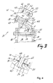
- the receiving element 41 is flat in the support area 36 of the support portion 31. Due to the recessed recess region of the support section 31, a gap S is created (see Fig. 4 ).
- the bearing means 63 is tightened with a lower torque than the clamping means 62, so that in the clamped state of the connecting device 21, a tensile force is exerted on the bearing means 63.
- the user is advantageously provided with the connection device 21 in this state.
- the clamping means 62 is released, wherein the receiving element 41 tilts over the tilting edge formed by the shoulder 35 in the direction of the side wall 24 of the mounting portion 23.
- the receiving element 41 is pivotable about a pivot axis 64 formed by the bearing means 63, without the bearing means 63 has to be solved.
- the tensioning means 62 again tense, the receiving element 41 tilts back again until it rests again flat on the support portion 36 of the support portion 31 of the base member 22.
- the bearing means 63 is subjected to train, whereby the receiving element 41 is fixed in the desired orientation relative to the base member 22.
- the connecting device 71 shown differs from the connecting device 21 set out above by the arrangement of the contact area and the recess area on the contact side of the receiving element and by the other configuration of the fixing device 51 for fixing the transverse support profile 14 received in the receptacle 42. Otherwise, the elements of the connecting device 71 correspond with regard to the further features essentially the connection device 21.
- the support side 80 of the support portion 79 of the base member 72 is flat, along a plane without a provided in this paragraph.
- the receiving element 91 with the receptacle 92 for the transverse support profile 14 has on the contact side 95 of the abutment portion 94 a shoulder 98 which forms between the clamping means 112 and the bearing means 113 of the locking device 111 a support area 96 and a recessed area 97 of the plant side 95.
- the receiving element 91 tilts towards the base member 72 and is pivotable relative to this about the pivot axis 114 formed by the bearing means 113.
- the arranged on the side wall 93 of the receiving element 91 fixing device 101 has a rear engagement part 104 which engages in the Schugreifnut 19 of the Quertragprofils 14 and via the clamping screws 107 and 108 for fixing the Quertragprofils 14 in the receptacle 92 is braced.
- curved extending slot 103 above the clamping means 112 and provided in the side wall 93 bore 102 above the bearing means 113 is provided in the connecting device 71, provided in the side wall 93.
- the rear grip part 104 is pivotable about the pivot axis 109 formed by the clamping screw 107 for adjusting the inclination of the transverse support profile 14 received in the receptacle 92.
Landscapes
- Engineering & Computer Science (AREA)
- Chemical & Material Sciences (AREA)
- Life Sciences & Earth Sciences (AREA)
- Sustainable Development (AREA)
- Sustainable Energy (AREA)
- Thermal Sciences (AREA)
- Physics & Mathematics (AREA)
- Combustion & Propulsion (AREA)
- Mechanical Engineering (AREA)
- General Engineering & Computer Science (AREA)
- Clamps And Clips (AREA)
- Photovoltaic Devices (AREA)
- Connection Of Plates (AREA)
Applications Claiming Priority (1)
| Application Number | Priority Date | Filing Date | Title |
|---|---|---|---|
| DE102009045209A DE102009045209A1 (de) | 2009-09-30 | 2009-09-30 | Verbindungsvorrichtung für eine Ständerkonstruktion |
Publications (2)
| Publication Number | Publication Date |
|---|---|
| EP2312236A2 true EP2312236A2 (fr) | 2011-04-20 |
| EP2312236A3 EP2312236A3 (fr) | 2014-03-12 |
Family
ID=43339819
Family Applications (1)
| Application Number | Title | Priority Date | Filing Date |
|---|---|---|---|
| EP10174669.1A Withdrawn EP2312236A3 (fr) | 2009-09-30 | 2010-08-31 | Dispositif de liaison pour une construction de support |
Country Status (4)
| Country | Link |
|---|---|
| US (1) | US8407961B2 (fr) |
| EP (1) | EP2312236A3 (fr) |
| CA (1) | CA2716241A1 (fr) |
| DE (1) | DE102009045209A1 (fr) |
Cited By (2)
| Publication number | Priority date | Publication date | Assignee | Title |
|---|---|---|---|---|
| WO2013143517A3 (fr) * | 2012-03-30 | 2013-12-19 | Haticon Gmbh | Système de bâti pour plein air |
| WO2020049374A1 (fr) * | 2018-09-03 | 2020-03-12 | S-Rack K.K. | Ferrure d'ajustage et système de support pour modules solaires |
Families Citing this family (10)
| Publication number | Priority date | Publication date | Assignee | Title |
|---|---|---|---|---|
| US8661747B2 (en) * | 2010-07-23 | 2014-03-04 | Kristian Eide | Solar panel racking system |
| DE102011104452A1 (de) | 2011-06-08 | 2012-12-13 | Schletter Gmbh | Ständer für PV-Module |
| WO2012167774A2 (fr) | 2011-06-08 | 2012-12-13 | Schletter Gmbh | Support pour modules pv |
| DE102011104455B4 (de) | 2011-06-08 | 2013-01-03 | Schletter Gmbh | Baugruppe eines Ständers für PV-Module, Halteaufsatz und Verfahren zum Montieren der Baugruppe |
| US20130098858A1 (en) * | 2011-09-27 | 2013-04-25 | Northern States Metals Company | Support system for solar panels with modified joists |
| CA2860607A1 (fr) * | 2012-03-15 | 2013-09-19 | Magna International Inc. | Structure de montage de panneau solaire |
| DE102012011969B4 (de) * | 2012-03-19 | 2016-11-03 | K2 Systems Gmbh | Solarmodulhalter |
| US9316417B2 (en) * | 2012-06-29 | 2016-04-19 | Sunpower Corporation | Framing system for mounting solar collecting devices |
| DE202012104634U1 (de) * | 2012-11-29 | 2014-03-03 | Habdank Pv-Montagesysteme Gmbh & Co. Kg | Montagesystem für Solarmodule |
| DE102017102827B3 (de) * | 2017-02-13 | 2018-06-21 | Mounting Systems Gmbh | Trägervorrichtung mit C-Profil-Modulträger für Solarmodule |
Citations (1)
| Publication number | Priority date | Publication date | Assignee | Title |
|---|---|---|---|---|
| DE202006014047U1 (de) | 2006-09-13 | 2006-12-07 | Leichtmetallbau Schletter Gmbh | Stellsystem für aufgeständerte Solaranlagen |
Family Cites Families (8)
| Publication number | Priority date | Publication date | Assignee | Title |
|---|---|---|---|---|
| US4966631A (en) * | 1989-03-13 | 1990-10-30 | Chronar Corp. | Support for photovoltaic arrays |
| DE19934073B4 (de) * | 1999-07-19 | 2005-08-25 | Regen Energiesysteme Gmbh | Vorrichtung zur Befestigung von Solarmodulen |
| US6414237B1 (en) * | 2000-07-14 | 2002-07-02 | Astropower, Inc. | Solar collectors, articles for mounting solar modules, and methods of mounting solar modules |
| US7017317B2 (en) * | 2002-10-04 | 2006-03-28 | Leonard Thomas Capozzo | Decorative ceiling panel and fastening system |
| US7531741B1 (en) * | 2003-03-07 | 2009-05-12 | Sacred Power Corporation | Tracking solar shelter |
| DE202008001010U1 (de) * | 2008-01-23 | 2008-05-08 | SGGT Straßenausstattungen GmbH | Tragkonstruktion für Solarmodule |
| US8046961B1 (en) * | 2008-05-27 | 2011-11-01 | Solarcraft, Inc. | Tactical solar power system |
| DE202010000293U1 (de) * | 2009-10-09 | 2010-05-20 | Galaxy-Energy Gmbh | Solardachanordnung |
-
2009
- 2009-09-30 DE DE102009045209A patent/DE102009045209A1/de not_active Withdrawn
-
2010
- 2010-08-31 EP EP10174669.1A patent/EP2312236A3/fr not_active Withdrawn
- 2010-09-29 US US12/893,488 patent/US8407961B2/en not_active Expired - Fee Related
- 2010-09-30 CA CA2716241A patent/CA2716241A1/fr not_active Abandoned
Patent Citations (1)
| Publication number | Priority date | Publication date | Assignee | Title |
|---|---|---|---|---|
| DE202006014047U1 (de) | 2006-09-13 | 2006-12-07 | Leichtmetallbau Schletter Gmbh | Stellsystem für aufgeständerte Solaranlagen |
Cited By (4)
| Publication number | Priority date | Publication date | Assignee | Title |
|---|---|---|---|---|
| WO2013143517A3 (fr) * | 2012-03-30 | 2013-12-19 | Haticon Gmbh | Système de bâti pour plein air |
| WO2020049374A1 (fr) * | 2018-09-03 | 2020-03-12 | S-Rack K.K. | Ferrure d'ajustage et système de support pour modules solaires |
| TWI707104B (zh) * | 2018-09-03 | 2020-10-11 | 日商思銳可股份有限公司 | 太陽能板之調整配件及攜載系統 |
| JP2021536208A (ja) * | 2018-09-03 | 2021-12-23 | S−Rack株式会社 | ソーラーパネル用の調節金具および支持システム |
Also Published As
| Publication number | Publication date |
|---|---|
| EP2312236A3 (fr) | 2014-03-12 |
| US20110072741A1 (en) | 2011-03-31 |
| DE102009045209A1 (de) | 2011-03-31 |
| CA2716241A1 (fr) | 2011-03-30 |
| US8407961B2 (en) | 2013-04-02 |
Similar Documents
| Publication | Publication Date | Title |
|---|---|---|
| EP2312236A2 (fr) | Dispositif de liaison pour une construction de support | |
| DE102013112645B3 (de) | Türband | |
| EP2604867B1 (fr) | Pince | |
| EP2495507A1 (fr) | Elément de fixation pour cadres de module solaire | |
| EP2527762A1 (fr) | Dispositif de fixation | |
| EP1561956A1 (fr) | Dispositif de raccordement | |
| DE102005018687B3 (de) | An einem Dacheindeckungselement angebrachte Halterung zur lösbaren Befestigung eines Gegenstandes, insbesondere eines Solarmoduls | |
| EP2256432A2 (fr) | Support pour modules solaires carrés | |
| EP2372269A2 (fr) | Dispositif de liaison et agencement de profilé | |
| EP1960603A1 (fr) | Dispositif de fixation d'un support pour détecteurs, moyens de commutation et similaires sur des rails | |
| EP0064290A1 (fr) | Dispositif de fixation de panneaux de revêtement aux éléments de construction | |
| DE4002420A1 (de) | Anker fuer die befestigung von fassadenplatten an einer wand | |
| DE102018127282A1 (de) | Baugruppe eines Bandes zur um eine Scharnierachse scharniergelenkigen Verbindung eines Flügels mit einem Rahmen sowie Band mit dieser Baugruppe | |
| WO2010000403A2 (fr) | Stabilisateur à dispositif d'ajustage pour des ancrages au sol | |
| DE102009022780A1 (de) | Ständer für rechteckige Solarmodule | |
| EP4411275B1 (fr) | Crochet de toit | |
| CH700182B1 (de) | Rohrhalterung. | |
| EP0931885A2 (fr) | Caniveau d'écoulement | |
| DE202005002790U1 (de) | Bausatz zur Verbindung von Trägerelementen | |
| DE102015118360A1 (de) | Halterung für plattenelemente von brüstungen, geländern und dergleichen | |
| EP2669959A2 (fr) | Structure porteuse pour panneaux solaires | |
| DE19860743C1 (de) | Wandhalter für Verkleidungstafeln, insbesondere Fassadenelemente | |
| EP2298992A2 (fr) | Agencement d'absorbeur d'oscillations | |
| EP0731235A1 (fr) | Dispositif de montage pour protection solaire | |
| AT408682B (de) | Maueranker |
Legal Events
| Date | Code | Title | Description |
|---|---|---|---|
| PUAI | Public reference made under article 153(3) epc to a published international application that has entered the european phase |
Free format text: ORIGINAL CODE: 0009012 |
|
| AK | Designated contracting states |
Kind code of ref document: A2 Designated state(s): AL AT BE BG CH CY CZ DE DK EE ES FI FR GB GR HR HU IE IS IT LI LT LU LV MC MK MT NL NO PL PT RO SE SI SK SM TR |
|
| AX | Request for extension of the european patent |
Extension state: BA ME RS |
|
| PUAL | Search report despatched |
Free format text: ORIGINAL CODE: 0009013 |
|
| AK | Designated contracting states |
Kind code of ref document: A3 Designated state(s): AL AT BE BG CH CY CZ DE DK EE ES FI FR GB GR HR HU IE IS IT LI LT LU LV MC MK MT NL NO PL PT RO SE SI SK SM TR |
|
| AX | Request for extension of the european patent |
Extension state: BA ME RS |
|
| RIC1 | Information provided on ipc code assigned before grant |
Ipc: E04B 1/26 20060101ALI20140205BHEP Ipc: E04B 1/19 20060101ALI20140205BHEP Ipc: F24J 2/52 20060101AFI20140205BHEP Ipc: E04B 1/24 20060101ALI20140205BHEP |
|
| 17P | Request for examination filed |
Effective date: 20140912 |
|
| RBV | Designated contracting states (corrected) |
Designated state(s): AL AT BE BG CH CY CZ DE DK EE ES FI FR GB GR HR HU IE IS IT LI LT LU LV MC MK MT NL NO PL PT RO SE SI SK SM TR |
|
| GRAP | Despatch of communication of intention to grant a patent |
Free format text: ORIGINAL CODE: EPIDOSNIGR1 |
|
| INTG | Intention to grant announced |
Effective date: 20141209 |
|
| GRAS | Grant fee paid |
Free format text: ORIGINAL CODE: EPIDOSNIGR3 |
|
| STAA | Information on the status of an ep patent application or granted ep patent |
Free format text: STATUS: THE APPLICATION IS DEEMED TO BE WITHDRAWN |
|
| 18D | Application deemed to be withdrawn |
Effective date: 20150421 |