EP0931892A2 - Elément de fixation et son utilisation - Google Patents
Elément de fixation et son utilisation Download PDFInfo
- Publication number
- EP0931892A2 EP0931892A2 EP99100925A EP99100925A EP0931892A2 EP 0931892 A2 EP0931892 A2 EP 0931892A2 EP 99100925 A EP99100925 A EP 99100925A EP 99100925 A EP99100925 A EP 99100925A EP 0931892 A2 EP0931892 A2 EP 0931892A2
- Authority
- EP
- European Patent Office
- Prior art keywords
- head
- web
- fastening element
- element according
- opening
- Prior art date
- Legal status (The legal status is an assumption and is not a legal conclusion. Google has not performed a legal analysis and makes no representation as to the accuracy of the status listed.)
- Granted
Links
- 239000012774 insulation material Substances 0.000 claims abstract description 4
- 238000009413 insulation Methods 0.000 claims description 21
- 239000000463 material Substances 0.000 claims description 8
- 239000011810 insulating material Substances 0.000 claims description 2
- 239000002184 metal Substances 0.000 claims description 2
- 238000011161 development Methods 0.000 description 5
- 230000018109 developmental process Effects 0.000 description 5
- 239000006260 foam Substances 0.000 description 4
- 238000004026 adhesive bonding Methods 0.000 description 2
- 239000002657 fibrous material Substances 0.000 description 2
- 238000010276 construction Methods 0.000 description 1
- 230000001419 dependent effect Effects 0.000 description 1
- 238000005553 drilling Methods 0.000 description 1
- 239000000835 fiber Substances 0.000 description 1
- 238000003780 insertion Methods 0.000 description 1
- 230000037431 insertion Effects 0.000 description 1
- 238000004519 manufacturing process Methods 0.000 description 1
- 230000035515 penetration Effects 0.000 description 1
- 239000003380 propellant Substances 0.000 description 1
Images

Classifications
-
- E—FIXED CONSTRUCTIONS
- E04—BUILDING
- E04B—GENERAL BUILDING CONSTRUCTIONS; WALLS, e.g. PARTITIONS; ROOFS; FLOORS; CEILINGS; INSULATION OR OTHER PROTECTION OF BUILDINGS
- E04B1/00—Constructions in general; Structures which are not restricted either to walls, e.g. partitions, or floors or ceilings or roofs
- E04B1/62—Insulation or other protection; Elements or use of specified material therefor
- E04B1/74—Heat, sound or noise insulation, absorption, or reflection; Other building methods affording favourable thermal or acoustical conditions, e.g. accumulating of heat within walls
- E04B1/76—Heat, sound or noise insulation, absorption, or reflection; Other building methods affording favourable thermal or acoustical conditions, e.g. accumulating of heat within walls specifically with respect to heat only
- E04B1/762—Exterior insulation of exterior walls
- E04B1/7629—Details of the mechanical connection of the insulation to the wall
- E04B1/7633—Dowels with enlarged insulation retaining head
-
- E—FIXED CONSTRUCTIONS
- E04—BUILDING
- E04F—FINISHING WORK ON BUILDINGS, e.g. STAIRS, FLOORS
- E04F13/00—Coverings or linings, e.g. for walls or ceilings
- E04F13/07—Coverings or linings, e.g. for walls or ceilings composed of covering or lining elements; Sub-structures therefor; Fastening means therefor
- E04F13/08—Coverings or linings, e.g. for walls or ceilings composed of covering or lining elements; Sub-structures therefor; Fastening means therefor composed of a plurality of similar covering or lining elements
- E04F13/0801—Separate fastening elements
- E04F13/0832—Separate fastening elements without load-supporting elongated furring elements between wall and covering elements
- E04F13/0833—Separate fastening elements without load-supporting elongated furring elements between wall and covering elements not adjustable
- E04F13/0835—Separate fastening elements without load-supporting elongated furring elements between wall and covering elements not adjustable the fastening elements extending into the back side of the covering elements
Definitions
- the invention has for its object a mounting option to create an improved hold of Insulation boards or mats on facades.
- the invention proposes a fastener with the features of claim 1 and its Use with the features mentioned in claim 23 above.
- Developments of the invention are the subject of the dependent Claims, the wording of which is the same as the wording of the summary by reference to the content of the description is made.
- the fastener makes it possible to use the insulation materials only by dowels or screws on the facade fasten without the need for gluing.
- the at least one web serve the fastening bolt on the surface of the Support the wall so that it can also shear and bend can be stressed by the weight of the panels.
- the area increases, on which the weight of the insulation board rests, so that this is kept better.
- the area on which the insulation element rests is so small that it is deformed and can slide down.
- the edge of the web facing away from the head of the fastening element at least partially in a plane parallel to the plane of the Head runs.
- insulation boards for example If there is hard foam, the web can penetrate the material and separate this.
- the at least one web on the Fit the surface of the facade so that the web not only support or support over its entire surface, but also can serve as a stop. But it is not necessary that the web extends to the facade surface during assembly.
- At least one web is flat.
- At least one web is formed curved.
- the invention proposes that in the presence of several Two webs, for example, lie in one plane.
- At least one web preferably all webs, approximately radially run. Under radial is the direction starting from the To understand the axis of the fastening bolt.
- the opening is central is arranged in the head element.
- the webs can be further developed at the back of the head be attached. This leads to a great stability of the Fastening element and the further advantage that the webs can affect the entire thickness of the insulation material.
- At least one radially extending web extends approximately to the edge of the head.
- the edge of the web facing away from the head is thinner be as the footbridge in its other area. It is also possible to form this edge with sharp edges.
- the fasteners are also used with insulation boards can and should be made of fibrous material, can be provided according to the invention that the head opposite edge of at least one web has a recess having. If the fibers do not cut or let it split up, just squeeze it together, this recess facilitates the insertion of the fastener.
- the invention can be provided so that it extends from the edge of the opening of the head proceeding outwards.
- a sleeve element is arranged by the mounting bolt in the assembled state reaches through.
- This sleeve element can also serve to stiffen the fastener. It can be provided that it is at least up to the level of free edges of the web is sufficient.
- At least one Web is attached to the sleeve member.
- the dimensions of the Opening the head of the fastener and / or the sleeve are designed such that they are the dimensions of a dowel correspond.
- Another way proposed by the invention is, is the fastener as part of a Form dowels, especially as a one-piece part.
- the invention proposes that the opening in the Fastener is formed such that a bolt can be set in it with a bolt gun can be driven.
- a bolt gun can be driven.
- Such bolt guns that with a propellant charge are known for this purpose.
- the fastener according to the invention can in particular be produced as a one-piece plastic part.
- the invention proposes in training, on the A mark on the front of the head element facing away from the webs attach, for example a diametrical line, the when mounting the fastener horizontally or also to be aligned vertically.
- This marking is so matched to the bridges that the fitter with the instruction align the line horizontally, the correct one you want Alignment of the webs on the back, which he then does not sees, manufactures.
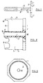
- Fig. 1 shows a view of a fastener after the invention.
- the fastener includes a head member 1 in the form of, for example, an octagonal level Plate.
- the head element could also be a slightly curved one Front 2 have.
- On the flat back 3 of the Head element 1 is centrally a sleeve element 4 in the form of a cylindrical sleeve molded in one piece. From the scope of the Sleeve elements 4 extend radially from two webs 5 outside, the outer edges 6 of both webs 5 parallel to each other and to the longitudinal axis of the sleeve element 4 and slightly in relation to the outer edges 7 of the head element 1 are reset.
- Edges 8 of the webs 5 both lie in a common plane, which are parallel to the plane of the rear side 3 of the head element 1 runs.
- the webs are along their entire length on the Fixed sleeve element 4, in particular in one piece with this.
- FIG. 2 shows a view of the fastening element of FIG. 1 from above.
- the two webs 5 run in the longitudinal direction of the Sleeve element 4 over almost the entire length of the sleeve element, but do not quite reach the free end 9 of the Sleeve element 4.
- the rear edge 8 of the web 5 is narrow, while the thickness of the web 5 towards the head element 1 increases.
- FIG. 3 now shows the rear view of the fastener.
- An extension of the sleeve element 4 is in the head element 1 an opening 10 is arranged so that through the sleeve element 4th a fastening bolt can reach through.
- the fastener of Figures 1 to 3 is as follows used.
- a layer of plate material is first a Dowel hole drilled and a conventional dowel in this hole inserted flush with the top of the facade. Then it will be the insulation board is applied to the facade without gluing it.
- a fastener is in alignment with the dowel pressed into the front of the insulation board, the two webs 5 can be arranged horizontally. This can for example by one on the front 2 of the head element 1 attached marking can be checked.
- When pushing in the webs 5 penetrate into the material of the insulation board on. If it is a rigid foam, it will cut through the two webs, for example. At fibrous material is pressed in.
- the insulation board rests then on a significantly enlarged area, not only on the sleeve 4. As a result, the material can not push through and the insulation board is held securely.
- the embodiment according to FIG. 4 now uses three Crosspieces 5 that are even around the axis of the hole 10 are arranged radially. In this case enlarged both the surface on which the weight of the insulation board rests, as well as the resistance to shear stress, since the respective lower web 5 supports the Fastener on the facade surface takes over.
- FIG. 5 Embodiment A further improvement is shown in FIG. 5 Embodiment in which at the rear 3 of the Head element 1 arranged four evenly spaced webs 5 are.
- a sleeve element 4 is present is, on which the webs 5 are integrally formed and thus fastened 6, the embodiment according to FIG Possibility of getting by without a sleeve element 4.
- the webs 5 are attached to the rear 13 of the head element 1, molded in one piece, for example.
- This fastener can be used in the same way as the previous one dealt with embodiments. At most the threading of the Fastening bolt can be a little more difficult.
- FIG. 7 shows the use of dowels a dowel 11, in which the fastener with the Head plate 1 and the webs 5 an integral part of the Dowels 11 forms.
- the front part of the anchor can be in the be formed in the same or a similar manner as that Fasteners according to Figures 1 to 6, during the remaining part of the dowel 11 in the same or a similar It is constructed in the same way as the well-known dowels of the most varied Species.
- Fig. 8 now shows on an enlarged scale the partially sectional side view of a fastener, the contains various options for further training that not necessarily all realized with one fastener have to be.
- the sleeve element 4 has a smooth Inner opening 12 in the hole 10 of the head element transforms.
- the inner diameter of the smooth inner opening 12 For example, the inside diameter of the front section correspond to a dowel, so that for the dowel used fastening bolts in an extended form Attachment of the fastener on the dowel can serve.
- the opening 10 and the sleeve member 4 dimensioned so that an entire dowel can be inserted through the sleeve element 4, the then in its front area in the sleeve element 4 remains arranged.
- the rear edge 8 of the web 5 at the top in FIG. 8 contains one Recess 13 into which the material of the insulation board is pressed in case it is not from the rear Cut or split edge 8 of the web.
- the lower web 5 then contains two in its rear edge 8 Recesses 13.
- FIG. 9 shows a rear view of a further fastening element, in this there is a single web 5, the is designed as an annular cylindrical apron and with runs a small distance from the edge 7 of the head element 1.
- the apron is concentric with the opening 10 in the head element 1 arranged.
- the web 5 fully penetrate the rigid foam and also both the strength of the attachment against shear off as well increase the contact area of the insulation board.
Landscapes
- Engineering & Computer Science (AREA)
- Architecture (AREA)
- Structural Engineering (AREA)
- Civil Engineering (AREA)
- Physics & Mathematics (AREA)
- Acoustics & Sound (AREA)
- Electromagnetism (AREA)
- Finishing Walls (AREA)
- Slide Fasteners, Snap Fasteners, And Hook Fasteners (AREA)
- Thermotherapy And Cooling Therapy Devices (AREA)
- Saccharide Compounds (AREA)
- Joining Of Building Structures In Genera (AREA)
- Load-Bearing And Curtain Walls (AREA)
- Connection Of Plates (AREA)
Priority Applications (1)
| Application Number | Priority Date | Filing Date | Title |
|---|---|---|---|
| DK99100925T DK0931892T3 (da) | 1998-01-21 | 1999-01-20 | Fastgörelseselement og dettes anvendelse |
Applications Claiming Priority (2)
| Application Number | Priority Date | Filing Date | Title |
|---|---|---|---|
| DE19802063 | 1998-01-21 | ||
| DE19802063A DE19802063A1 (de) | 1998-01-21 | 1998-01-21 | Befestigungselement und seine Verwendung |
Publications (3)
| Publication Number | Publication Date |
|---|---|
| EP0931892A2 true EP0931892A2 (fr) | 1999-07-28 |
| EP0931892A3 EP0931892A3 (fr) | 1999-10-20 |
| EP0931892B1 EP0931892B1 (fr) | 2004-11-03 |
Family
ID=7855191
Family Applications (1)
| Application Number | Title | Priority Date | Filing Date |
|---|---|---|---|
| EP99100925A Expired - Lifetime EP0931892B1 (fr) | 1998-01-21 | 1999-01-20 | Elément de fixation et son utilisation |
Country Status (6)
| Country | Link |
|---|---|
| EP (1) | EP0931892B1 (fr) |
| AT (1) | ATE281575T1 (fr) |
| DE (2) | DE19802063A1 (fr) |
| DK (1) | DK0931892T3 (fr) |
| ES (1) | ES2232036T3 (fr) |
| PT (1) | PT931892E (fr) |
Cited By (1)
| Publication number | Priority date | Publication date | Assignee | Title |
|---|---|---|---|---|
| EP2840201A1 (fr) * | 2001-12-05 | 2015-02-25 | EJOT GmbH & Co. KG | Dispositif d'enfoncement d'un élément expansible dans une cheville. |
Families Citing this family (3)
| Publication number | Priority date | Publication date | Assignee | Title |
|---|---|---|---|---|
| DE10214229C5 (de) * | 2002-03-25 | 2013-04-18 | Böger Systemklinker Produktions GmbH | Schraubbuchse und Verfahren zur Herstellung eines Verkleidungselements und mit Schraubbuchsen versehenes Verkleidungselement |
| DE102007060954A1 (de) * | 2007-12-18 | 2009-06-25 | Fischerwerke Gmbh & Co. Kg | Setzeinheit und Setzverfahren |
| DE102011056105B4 (de) * | 2010-12-17 | 2013-12-24 | Georg Lantenhammer | Montagezusatzelement für die Befestigung von Bauelementen, z.B. Kellerlichtschächten an Gebäudewänden |
Family Cites Families (9)
| Publication number | Priority date | Publication date | Assignee | Title |
|---|---|---|---|---|
| US2201129A (en) * | 1938-08-26 | 1940-05-14 | Butler Weiland Corp | Tiling |
| DE1955200A1 (de) * | 1969-11-03 | 1971-05-13 | Hansjuergen Doss | Vorrichtung fuer das Einbauen und Ausrichten von Mauerverkleidungsplatten aller Art |
| DE7932608U1 (de) * | 1979-11-17 | 1980-06-12 | Faester Gmbh Und Co Kg Befestigungstechnik, 7800 Freiburg | Mehrteiliger Dübel aus Kunststoff für die Befestigung und Verbindung von plattenförmigen Bauteilen an einem Bauwerk |
| DE8225725U1 (de) * | 1982-09-13 | 1982-12-09 | Upat Gmbh & Co, 7830 Emmendingen | Isolierplatten-duebel |
| DE3321623C2 (de) * | 1983-02-10 | 1987-01-29 | Raimund 7730 Villingen-Schwenningen Andris | Isolierplattendübel aus Kunststoff |
| US4803823A (en) * | 1987-04-28 | 1989-02-14 | Stenson John F | Rigid insulation corner fastener |
| DE8714335U1 (de) * | 1987-10-28 | 1988-01-07 | Ejot Adolf Böhl GmbH & Co KG, 5920 Bad Berleburg | Abstandshalter für die Befestigung von Armierungsgittern |
| DE3907034A1 (de) * | 1989-03-04 | 1990-09-06 | Upat Max Langensiepen Kg | Spreizduebel |
| US5217339A (en) * | 1992-06-30 | 1993-06-08 | Performance Building Products, Inc. | Non-seating plate/fastener assembly |
-
1998
- 1998-01-21 DE DE19802063A patent/DE19802063A1/de not_active Withdrawn
-
1999
- 1999-01-20 DK DK99100925T patent/DK0931892T3/da active
- 1999-01-20 ES ES99100925T patent/ES2232036T3/es not_active Expired - Lifetime
- 1999-01-20 EP EP99100925A patent/EP0931892B1/fr not_active Expired - Lifetime
- 1999-01-20 DE DE59910958T patent/DE59910958D1/de not_active Expired - Fee Related
- 1999-01-20 AT AT99100925T patent/ATE281575T1/de not_active IP Right Cessation
- 1999-01-20 PT PT99100925T patent/PT931892E/pt unknown
Non-Patent Citations (1)
| Title |
|---|
| None |
Cited By (1)
| Publication number | Priority date | Publication date | Assignee | Title |
|---|---|---|---|---|
| EP2840201A1 (fr) * | 2001-12-05 | 2015-02-25 | EJOT GmbH & Co. KG | Dispositif d'enfoncement d'un élément expansible dans une cheville. |
Also Published As
| Publication number | Publication date |
|---|---|
| DK0931892T3 (da) | 2005-02-14 |
| DE59910958D1 (de) | 2004-12-09 |
| ATE281575T1 (de) | 2004-11-15 |
| EP0931892B1 (fr) | 2004-11-03 |
| DE19802063A1 (de) | 1999-07-22 |
| ES2232036T3 (es) | 2005-05-16 |
| EP0931892A3 (fr) | 1999-10-20 |
| PT931892E (pt) | 2005-03-31 |
Similar Documents
| Publication | Publication Date | Title |
|---|---|---|
| EP3433440B1 (fr) | Procédé d'assemblage de poutres en bois | |
| EP0292742B1 (fr) | Vis d'écartement | |
| EP0336183B1 (fr) | Dispositif de fixation d'une partie filetée dans un trou à chambrage | |
| DE102006049954A1 (de) | Dübel für Deckplattenhinter- und eingriff | |
| EP0918164A1 (fr) | Vis de réglage | |
| DE102012103591A1 (de) | Verbindungsmittel zur Kopplung von zwei Bauelementen | |
| EP2184421B1 (fr) | Elément de fixation pour un système de mise en place d'un revêtement de mur, de sol ou de plafond ainsi qu'un tel système de mise en place | |
| DE2243102A1 (de) | Tragstuetze fuer aufgestaenderte fussboeden | |
| DE102004064114B4 (de) | Befestigungselement für Dämmstoffplatten | |
| DE102006049953A1 (de) | Dübel für Deckplattenhintergriff | |
| EP2971400B1 (fr) | Douille et élément de fixation pour fixer une couche de matériau | |
| EP0931892B1 (fr) | Elément de fixation et son utilisation | |
| EP2117383A2 (fr) | Douille à blocage de plaque de recouvrement et expansion d'alésage | |
| DE3333055C2 (de) | Vorrichtung zum Befestigen von Latten | |
| EP0935075B1 (fr) | Dispositif de fixation d'un élément de liaison à une distance sur une structure porteuse | |
| DE3427608C2 (fr) | ||
| EP0872619A2 (fr) | Elément d'ajustement | |
| DE202008013611U1 (de) | Spreizdübel und Anordnung eines Spreizdübels in einer Leichtbauplatte | |
| DE60023115T2 (de) | Verbindungssystem mit einer hülse zum beabstandeten halten von objekten | |
| DE19843293C2 (de) | An einer Stirnseite eines Holzständers befestigter Stützfuß | |
| WO2005061811A1 (fr) | Construction de parois en bois, du type a madriers en blocs | |
| DE3611873A1 (de) | Befestigungselement zum verstellbaren befestigen von bauelementen an bauwerken | |
| EP0034346A1 (fr) | Dispositif de fixation pour fixer des revêtements, listeaux ou analogues sur un mur au moyen d'une cheville à tête de serrage en matière plastique | |
| EP0617760B1 (fr) | Cheville de fixation de rail | |
| EP0380916A1 (fr) | Cheville pour plaque creuse |
Legal Events
| Date | Code | Title | Description |
|---|---|---|---|
| PUAI | Public reference made under article 153(3) epc to a published international application that has entered the european phase |
Free format text: ORIGINAL CODE: 0009012 |
|
| AK | Designated contracting states |
Kind code of ref document: A2 Designated state(s): AT BE CH DE DK ES FI FR GB GR IT LI NL PT SE |
|
| AX | Request for extension of the european patent |
Free format text: AL;LT;LV;MK;RO;SI |
|
| PUAL | Search report despatched |
Free format text: ORIGINAL CODE: 0009013 |
|
| AK | Designated contracting states |
Kind code of ref document: A3 Designated state(s): AT BE CH CY DE DK ES FI FR GB GR IE IT LI LU MC NL PT SE |
|
| AX | Request for extension of the european patent |
Free format text: AL;LT;LV;MK;RO;SI |
|
| 17P | Request for examination filed |
Effective date: 20000324 |
|
| AKX | Designation fees paid |
Free format text: AT BE CH DE DK ES FI FR GB GR IT LI NL PT SE |
|
| 17Q | First examination report despatched |
Effective date: 20030616 |
|
| GRAP | Despatch of communication of intention to grant a patent |
Free format text: ORIGINAL CODE: EPIDOSNIGR1 |
|
| GRAS | Grant fee paid |
Free format text: ORIGINAL CODE: EPIDOSNIGR3 |
|
| GRAA | (expected) grant |
Free format text: ORIGINAL CODE: 0009210 |
|
| AK | Designated contracting states |
Kind code of ref document: B1 Designated state(s): AT BE CH DE DK ES FI FR GB GR IT LI NL PT SE |
|
| REG | Reference to a national code |
Ref country code: GB Ref legal event code: FG4D Free format text: NOT ENGLISH |
|
| REG | Reference to a national code |
Ref country code: CH Ref legal event code: EP |
|
| REF | Corresponds to: |
Ref document number: 59910958 Country of ref document: DE Date of ref document: 20041209 Kind code of ref document: P |
|
| PGFP | Annual fee paid to national office [announced via postgrant information from national office to epo] |
Ref country code: GB Payment date: 20050112 Year of fee payment: 7 |
|
| PGFP | Annual fee paid to national office [announced via postgrant information from national office to epo] |
Ref country code: NL Payment date: 20050118 Year of fee payment: 7 |
|
| PGFP | Annual fee paid to national office [announced via postgrant information from national office to epo] |
Ref country code: FR Payment date: 20050119 Year of fee payment: 7 |
|
| PGFP | Annual fee paid to national office [announced via postgrant information from national office to epo] |
Ref country code: DK Payment date: 20050121 Year of fee payment: 7 |
|
| PGFP | Annual fee paid to national office [announced via postgrant information from national office to epo] |
Ref country code: FI Payment date: 20050124 Year of fee payment: 7 Ref country code: ES Payment date: 20050124 Year of fee payment: 7 |
|
| PGFP | Annual fee paid to national office [announced via postgrant information from national office to epo] |
Ref country code: SE Payment date: 20050125 Year of fee payment: 7 Ref country code: CH Payment date: 20050125 Year of fee payment: 7 Ref country code: BE Payment date: 20050125 Year of fee payment: 7 Ref country code: AT Payment date: 20050125 Year of fee payment: 7 |
|
| PGFP | Annual fee paid to national office [announced via postgrant information from national office to epo] |
Ref country code: GR Payment date: 20050126 Year of fee payment: 7 |
|
| REG | Reference to a national code |
Ref country code: CH Ref legal event code: NV Representative=s name: TROESCH SCHEIDEGGER WERNER AG |
|
| REG | Reference to a national code |
Ref country code: DK Ref legal event code: T3 |
|
| REG | Reference to a national code |
Ref country code: SE Ref legal event code: TRGR |
|
| PGFP | Annual fee paid to national office [announced via postgrant information from national office to epo] |
Ref country code: DE Payment date: 20050304 Year of fee payment: 7 |
|
| GBT | Gb: translation of ep patent filed (gb section 77(6)(a)/1977) |
Effective date: 20050214 |
|
| REG | Reference to a national code |
Ref country code: GR Ref legal event code: EP Ref document number: 20050400279 Country of ref document: GR |
|
| REG | Reference to a national code |
Ref country code: PT Ref legal event code: SC4A Free format text: AVAILABILITY OF NATIONAL TRANSLATION Effective date: 20050114 |
|
| REG | Reference to a national code |
Ref country code: ES Ref legal event code: FG2A Ref document number: 2232036 Country of ref document: ES Kind code of ref document: T3 |
|
| PLBE | No opposition filed within time limit |
Free format text: ORIGINAL CODE: 0009261 |
|
| STAA | Information on the status of an ep patent application or granted ep patent |
Free format text: STATUS: NO OPPOSITION FILED WITHIN TIME LIMIT |
|
| ET | Fr: translation filed | ||
| 26N | No opposition filed |
Effective date: 20050804 |
|
| PGFP | Annual fee paid to national office [announced via postgrant information from national office to epo] |
Ref country code: PT Payment date: 20060119 Year of fee payment: 8 |
|
| PG25 | Lapsed in a contracting state [announced via postgrant information from national office to epo] |
Ref country code: GB Free format text: LAPSE BECAUSE OF NON-PAYMENT OF DUE FEES Effective date: 20060120 Ref country code: FI Free format text: LAPSE BECAUSE OF NON-PAYMENT OF DUE FEES Effective date: 20060120 Ref country code: AT Free format text: LAPSE BECAUSE OF NON-PAYMENT OF DUE FEES Effective date: 20060120 |
|
| PG25 | Lapsed in a contracting state [announced via postgrant information from national office to epo] |
Ref country code: SE Free format text: LAPSE BECAUSE OF NON-PAYMENT OF DUE FEES Effective date: 20060121 Ref country code: ES Free format text: LAPSE BECAUSE OF NON-PAYMENT OF DUE FEES Effective date: 20060121 |
|
| PG25 | Lapsed in a contracting state [announced via postgrant information from national office to epo] |
Ref country code: LI Free format text: LAPSE BECAUSE OF NON-PAYMENT OF DUE FEES Effective date: 20060131 Ref country code: FR Free format text: LAPSE BECAUSE OF NON-PAYMENT OF DUE FEES Effective date: 20060131 Ref country code: DK Free format text: LAPSE BECAUSE OF NON-PAYMENT OF DUE FEES Effective date: 20060131 Ref country code: CH Free format text: LAPSE BECAUSE OF NON-PAYMENT OF DUE FEES Effective date: 20060131 Ref country code: BE Free format text: LAPSE BECAUSE OF NON-PAYMENT OF DUE FEES Effective date: 20060131 |
|
| PGFP | Annual fee paid to national office [announced via postgrant information from national office to epo] |
Ref country code: IT Payment date: 20060131 Year of fee payment: 8 |
|
| PG25 | Lapsed in a contracting state [announced via postgrant information from national office to epo] |
Ref country code: NL Free format text: LAPSE BECAUSE OF NON-PAYMENT OF DUE FEES Effective date: 20060801 Ref country code: DE Free format text: LAPSE BECAUSE OF NON-PAYMENT OF DUE FEES Effective date: 20060801 |
|
| REG | Reference to a national code |
Ref country code: DK Ref legal event code: EBP |
|
| REG | Reference to a national code |
Ref country code: CH Ref legal event code: PL |
|
| EUG | Se: european patent has lapsed | ||
| GBPC | Gb: european patent ceased through non-payment of renewal fee |
Effective date: 20060120 |
|
| NLV4 | Nl: lapsed or anulled due to non-payment of the annual fee |
Effective date: 20060801 |
|
| REG | Reference to a national code |
Ref country code: FR Ref legal event code: ST Effective date: 20060929 |
|
| REG | Reference to a national code |
Ref country code: ES Ref legal event code: FD2A Effective date: 20060121 |
|
| PG25 | Lapsed in a contracting state [announced via postgrant information from national office to epo] |
Ref country code: PT Free format text: LAPSE BECAUSE OF NON-PAYMENT OF DUE FEES Effective date: 20070720 |
|
| REG | Reference to a national code |
Ref country code: PT Ref legal event code: MM4A Free format text: LAPSE DUE TO NON-PAYMENT OF FEES Effective date: 20070720 |
|
| BERE | Be: lapsed |
Owner name: ADOLF *WURTH G.M.B.H. & CO. K.G. Effective date: 20060131 |
|
| PG25 | Lapsed in a contracting state [announced via postgrant information from national office to epo] |
Ref country code: GR Free format text: LAPSE BECAUSE OF NON-PAYMENT OF DUE FEES Effective date: 20060802 |
|
| PG25 | Lapsed in a contracting state [announced via postgrant information from national office to epo] |
Ref country code: IT Free format text: LAPSE BECAUSE OF NON-PAYMENT OF DUE FEES Effective date: 20070120 |