EP0931949B1 - Gleitlager - Google Patents
Gleitlager Download PDFInfo
- Publication number
- EP0931949B1 EP0931949B1 EP99810006A EP99810006A EP0931949B1 EP 0931949 B1 EP0931949 B1 EP 0931949B1 EP 99810006 A EP99810006 A EP 99810006A EP 99810006 A EP99810006 A EP 99810006A EP 0931949 B1 EP0931949 B1 EP 0931949B1
- Authority
- EP
- European Patent Office
- Prior art keywords
- bearing
- bearing surfaces
- sliding
- nozzles
- moving body
- Prior art date
- Legal status (The legal status is an assumption and is not a legal conclusion. Google has not performed a legal analysis and makes no representation as to the accuracy of the status listed.)
- Expired - Lifetime
Links
Images



Classifications
-
- F—MECHANICAL ENGINEERING; LIGHTING; HEATING; WEAPONS; BLASTING
- F16—ENGINEERING ELEMENTS AND UNITS; GENERAL MEASURES FOR PRODUCING AND MAINTAINING EFFECTIVE FUNCTIONING OF MACHINES OR INSTALLATIONS; THERMAL INSULATION IN GENERAL
- F16C—SHAFTS; FLEXIBLE SHAFTS; ELEMENTS OR CRANKSHAFT MECHANISMS; ROTARY BODIES OTHER THAN GEARING ELEMENTS; BEARINGS
- F16C32/00—Bearings not otherwise provided for
- F16C32/06—Bearings not otherwise provided for with moving member supported by a fluid cushion formed, at least to a large extent, otherwise than by movement of the shaft, e.g. hydrostatic air-cushion bearings
- F16C32/0603—Bearings not otherwise provided for with moving member supported by a fluid cushion formed, at least to a large extent, otherwise than by movement of the shaft, e.g. hydrostatic air-cushion bearings supported by a gas cushion, e.g. an air cushion
- F16C32/0614—Bearings not otherwise provided for with moving member supported by a fluid cushion formed, at least to a large extent, otherwise than by movement of the shaft, e.g. hydrostatic air-cushion bearings supported by a gas cushion, e.g. an air cushion the gas being supplied under pressure, e.g. aerostatic bearings
- F16C32/0622—Bearings not otherwise provided for with moving member supported by a fluid cushion formed, at least to a large extent, otherwise than by movement of the shaft, e.g. hydrostatic air-cushion bearings supported by a gas cushion, e.g. an air cushion the gas being supplied under pressure, e.g. aerostatic bearings via nozzles, restrictors
-
- F—MECHANICAL ENGINEERING; LIGHTING; HEATING; WEAPONS; BLASTING
- F16—ENGINEERING ELEMENTS AND UNITS; GENERAL MEASURES FOR PRODUCING AND MAINTAINING EFFECTIVE FUNCTIONING OF MACHINES OR INSTALLATIONS; THERMAL INSULATION IN GENERAL
- F16C—SHAFTS; FLEXIBLE SHAFTS; ELEMENTS OR CRANKSHAFT MECHANISMS; ROTARY BODIES OTHER THAN GEARING ELEMENTS; BEARINGS
- F16C29/00—Bearings for parts moving only linearly
- F16C29/02—Sliding-contact bearings
- F16C29/025—Hydrostatic or aerostatic
-
- F—MECHANICAL ENGINEERING; LIGHTING; HEATING; WEAPONS; BLASTING
- F16—ENGINEERING ELEMENTS AND UNITS; GENERAL MEASURES FOR PRODUCING AND MAINTAINING EFFECTIVE FUNCTIONING OF MACHINES OR INSTALLATIONS; THERMAL INSULATION IN GENERAL
- F16C—SHAFTS; FLEXIBLE SHAFTS; ELEMENTS OR CRANKSHAFT MECHANISMS; ROTARY BODIES OTHER THAN GEARING ELEMENTS; BEARINGS
- F16C32/00—Bearings not otherwise provided for
- F16C32/06—Bearings not otherwise provided for with moving member supported by a fluid cushion formed, at least to a large extent, otherwise than by movement of the shaft, e.g. hydrostatic air-cushion bearings
- F16C32/0681—Construction or mounting aspects of hydrostatic bearings, for exclusively rotary movement, related to the direction of load
- F16C32/0696—Construction or mounting aspects of hydrostatic bearings, for exclusively rotary movement, related to the direction of load for both radial and axial load
Definitions
- the invention relates to a method for sliding bearing and a sliding bearing according to the preambles of the corresponding independent claims, see US-A-4 234 175.
- the sliding bearing according to the invention is applicable for the storage of rotating shafts or spindles or for the storage of translationally moving Bodies.
- Rotating or linearly moving machine parts become sliding (sliding bearing) stored or on freely rotating balls or rollers (rolling bearings).
- bearings are mechanically much easier compared to rolling bearings.
- plain bearings are limited mainly because of friction or Lubrication problems in the plain bearings due to the size of the adjacent and relative to each other moving storage areas (compared to the much smaller theoretically point or linear supports in rolling bearings) and because of the sliding friction (compared to the much smaller rolling friction in rolling bearings) are more difficult to solve. That's why it is an old concern of the mechanical engineering, be it for example by the development better lubricant or improved material pairings, the sliding bearing properties to improve such that plain bearings for applications become useful, in which according to the respective state of the art only proven rolling bearings.
- the object of the invention to provide a method for sliding storage and to provide a sliding bearing, such that the sliding bearing according to the invention compared with known plain bearings has improved properties especially with regard to friction or lubrication and with regard to wear.
- the sliding bearing according to the invention is intended, for example, in the application for mounting a tool or workpiece spindle in a machine tool can largely replace corresponding ball bearings.
- the invention is based on the application of fluid-dynamic laws on the technique of bearings.
- a fluid flow (Advantageously, an air flow) generated, such that through this air flow fluid dynamic, acting on the bearing surfaces forces generated become.
- the bearing surfaces of the movable and the stationary body are in this case designed such that the movable body and under the slide bearing External load to be absorbed by the fluid dynamic forces, the acting on its bearing surfaces, in a predetermined by the stationary body held in an equilibrium position, in which position it is non-contact and quasi-stable from the stationary body through a slit-shaped Cavity is spaced.
- the fluid flowing between the moving and stationary body fills up in addition to its function of generating the moving body positioning Forces also the function of a lubricant (in the case of air with extremely low friction) and at the same time the function of a coolant for Store cooling.
- Figure 1 shows a schematic representation of an axial section through a shaft 1 (rotor or moving body), which is supported by means of an exemplary embodiment of the inventive sliding bearing in a two, a receiving space forming parts 2 and 2 'existing stator.
- a bearing body 3 which is rigidly connected to the shaft (shrunk onto the shaft, for example) is provided, which is a body of revolution arranged coaxially with the shaft.
- the bearing body 3 is arranged in a corresponding receiving space in the stator 2.
- the overlapping on the fluid layer bearing surfaces L of the sliding bearing are arranged on the one hand on the surfaces of the bearing body 3 and the associated (inner) surfaces of the stator 2 in pairs opposite each other.
- the bearing surfaces L are shaped such that substantially each for a Considering any selected bearing surface area of both the rotor (Bearing body 3) and the stator 2 has a counter area, wherein a normal (perpendicular from the center of the range starting) of the considered Lager lake Kunststoffes and a normal of the corresponding counter area lying on the same straight line and facing each other are directed.
- this symmetry condition is connected to the bearing surfaces L of an inventive sliding bearing are provided, the example dess Area B on the bearing body 3 with a normal N and the opposite area B 'schematically indicated with a normal N'.
- this concerns Also, the arrangement of the holes through which bearing air is injected, as shown here by the example of the nozzles 4 and 4 '.
- the bearing body 3 shown in Figure 1 has for axial storage a radially, that is dish-shaped around the shaft extending part 3.1 and one for the radial bearing axially, that is, hollow cylindrical around the shaft 1 extending part 3.2.
- a radially that is dish-shaped around the shaft extending part 3.1
- one for the radial bearing axially that is, hollow cylindrical around the shaft 1 extending part 3.2.
- the stator 2 also has 4 holes acting as nozzles for pressing a fluid (eg air) between the bearing body 3 and the stator 2 and Exhaust ducts 5 for carrying away the between bearing body 3 and stator. 2 introduced air on.
- the nozzles could also be arranged in the bearing body be. It proves to be advantageous if the arrangement of the nozzles 4 and the Exhaust ducts 5 to each other also the above given symmetry conditions be assumed, that is, if for each in a storage area arranged nozzle and for each exhaust duct in the opposite area a corresponding nozzle and a corresponding exhaust duct is provided, such as this is shown in the embodiment according to FIG.
- the bearing surfaces L of the bearing body 3 and the bearing surfaces L of the stator 2 do not touch during operation.
- the slide bearing according to the invention is virtually frictionless and thereby not only essentially lossless operable but also essentially wear-free. This also means that the material pairing the successive sliding bearing surfaces is not relevant. Further are the properties of the inventive plain bearing substantially regardless of its location and independent of torque.
- FIGS. 2 to 4 serve to attempt to physically explain the phenomenon of the experimentally found function of the slide bearing according to the invention and its parameters and boundary conditions.
- Figures 2 and 3 show pressure and force relationships in a system in which the air of a pressure p 1 arranged through a arranged in a nozzle plate PD nozzle D, arranged substantially perpendicular to the nozzle plate PD, in a gap-shaped space between the nozzle plate PD and a counter plate PG is pressed against the pressure p 0 , which is less than p 1 (for example, against atmospheric pressure) is relaxed.
- the nozzle plate PD and the counter plate PG are close together, that is, the width of the gap between the two plates PD and PG is very small to zero. In such a case, in spite of pressure difference, substantially little to no air flows through the nozzle D.
- On the counter plate PG acts a pressure difference, which tries to push the counter plate away from the nozzle plate.
- the force K 1 acting on the counterplate PG is the pressure difference p 1 -p 0 multiplied by a surface F which is at least the cross-sectional area F D of the nozzle opening and at most the surface F P of the counterplate, depending on how the surfaces lie on one another.
- Figure 2 illustrates the static case.
- the nozzle plate PD and the counter plate PG are spaced from each other (distance d) such that air exits the nozzle D and relaxes in the space between the plates.
- the total pressure between the plates will be identical to the atmospheric pressure.
- the static pressure component P 2 is reduced by the dynamic pressure component p dyn , at atmospheric pressure, a force K 2 acting against the nozzle plate acts on the counterplate. This 'pulls' the back plate PG against the nozzle plate PD.
- the phenomenon described is known in physics as a hydrodynamic paradox. Since in operation, the nozzle opposite surface moves at great speed in one direction, other phenomena or effects that can not be explained here, have their effect.
- FIG. 4 shows, in a hypothetical transmission, the application to a bearing body 3 moved between two bearing surfaces of a stator 2, as shown in its entirety in FIG.
- a stator 2 two (on a common straight line) opposing bores or nozzles 4 are arranged, from which air is pressed into the gap-shaped cavities between the bearing body 3 and the stator 2.
- a diagram is recorded showing the presumable static pressure curve between bearing body and stator as a function of the distance between each two sliding bearing surfaces.
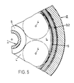
- Figure 5 shows a section of a section transverse to the axis through the sliding bearing according to Figure 1 (section line VV).
- the figure shows above all an axial plan view of the upper bearing surface L of the stator, on which the upper bearing surface of the plate-shaped bearing body part 3.1. slides.
- the fluid-dynamic effect of the air flowing out of the nozzles can be assumed to be substantially circularly symmetrical and decreases steadily with increasing distance from the nozzle due to the internal friction losses in the air, as provided.
- the effects of the individual nozzles are to be fully utilized, they are to be arranged such that their area of action (circular area on which the fluid-dynamic effect is not negligible, indicated in FIG. 5 with a dot-dash line around the nozzles 4) is not as far as possible, at least not overlap significantly.
- Experiments show that with a degree of freedom between bearing body and stator of 2 x 0.01 to 0.02 mm, at a working pressure between about 1.5 - 5 atü (1.5 to 5 ⁇ 10 5 Pa) and at an opening diameter
- This empirical value can be interpreted as the diameter of an area of activity in which the fluid-dynamic effect contributes to the function of the bearing in a manner which is not negligible. This also means that for the fullest possible utilization of the existing surfaces of a bearing body 3, the exhaust ducts 5 (here it grooves) should not be created further than about 40 mm away from the nozzles.
- the inventive Bear also external forces, such as the weight of the Rotor or load forces that act on the shaft, can absorb the fluid dynamic effective, that is overflowed with air storage areas the bearing body 3 and thus also the receiving space of the stator 2 such
- the disturbance forces only a small percentage of the fluid dynamic make out the forces generated.
- the inventive System is extremely robust against disturbing forces.
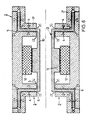
- Figure 6 shows schematically the essential parts of a spindle drive with two inventive sliding bearings, which correspond to the sliding bearing shown in the figure 1.
- At least parts of an electrically driven rotor 10 with a magnetic core 11 and bearing bodies 3 arranged at the ends are shown.
- the bearing body 3 receiving stator 2 is shown with a supplementing the driving electric motor coil 12 and a system for nozzles 4 and 5 discharges for the expanded air.
- Magnet core 11 and coil 12 together, as already said, an electric drive for driving the rotor 10.
- the degree of freedom between the rotor and stator is radially and axially 2 x 0.015 mm and the nozzles 4 have a ⁇ réellesd malmesser of about 0.5 mm.
- the air consumption of the sliding bearing according to the invention is relatively low.
- the air used should be free of solid particles, but must otherwise not specially prepared.
- FIGS. 7 and 8 also show a body 21 moved in a linear guide 20, the moving body being mounted in the linear guide according to the method according to the invention.
- Figure 7 shows a cross section through the system, in turn, bearing surfaces L, nozzles 4 and exhaust ducts 5 are shown, which meet the symmetry requirements mentioned above.
- Figure 8 is a three-dimensional representation of the system.
- the nozzles 4 are not arranged in the stationary but in the moving body, which is useful in view of the much larger extent of the bearing surfaces of the stator (linear guide) compared to the bearing surfaces of the moving body.
- FIG. 7 can also be regarded as a system of rotor 21 and stator 20.
- the bearing according to Figure 1 has the end of the rotating Shaft arranged bearing body only a radially extending, plate-shaped Part, while the function of the axially extending, hollow cylindrical Part of the wave itself is taken.
- the rotor according to FIG. 10 can be subjected to less radial load than the shaft of Figure 1, since the radially acting bearing surfaces are smaller.
Landscapes
- Engineering & Computer Science (AREA)
- General Engineering & Computer Science (AREA)
- Mechanical Engineering (AREA)
- Magnetic Bearings And Hydrostatic Bearings (AREA)
- Sliding-Contact Bearings (AREA)
Description
- Figur 1
- einen schematischen, axialen Schnitt durch eine beispielhafte Ausführungsform des erfindungsgemässen Gleitlagers für einen in einem Stator gelagerten Rotor;
- Figuren 2 bis 4
- schematische Darstellungen zur Erklärung des Funktionsprinzips des erfindungsgemässen Gleitlagers;
- Figur 5
- einen Schnitt quer zur Achse durch den Lagerkörper der Ausführungsform gemäss Figur 1 (Ausschnitt, Schnittlinie VI-VI in Figur 1);
- Figure 6
- eine Prinzip- und eine Detaildarstellung der Anwendung der Ausführungsform des erfindungsgemässen Gleitlagers gemäss Figur 1 für eine Spindel einer Werkzeugmaschine;
- Figuren 7 und 8
- in schematischer Darstellung eine beispielhafte Ausführungsform eines in einer Linearführung bewegten Körpers, wobei der Körper in der Linearführung nach dem erfindungsgemässen Verfahren gelagert ist (Figur 7: Querschnitt; Figur 8: räumliche Darstellung).
Claims (15)
- Verfahren zur Erwirkung einer gleitenden Lagerung eines rotierend oder linear bewegbaren Körpers (1/3, 21) in einem stationären Körper (2, 20), wobei einander entsprechende Lagerflächen (L) des bewegbaren Körpers und des stationären Körpers über ein Gleitmittel aufeinander gleiten, wobei zwischen aufeinander gleitenden Lagerflächen (L) Fluidströmungen erzeugt werden, durch die der statische Druck (p2) zwischen den aufeinander gleitenden Lagerflächen (L) reduziert wird und zwischen dem stationären Körper und dem bewegten Körper (1/3, 21) Druckkräfte entstehen, wobei die Fluidströmungen und die Lagerflächen derart aufeinander abgestimmt werden, dass alle auf den bewegten Körper wirkenden Druckkräfte sich im wesentlichen gegenseitig aufheben, sobald der bewegte Körper (1/3, 21) in einer den stationären Körper (2, 20) nicht berührenden Gleichgewichtslage positioniert ist, und bei Auslenkung aus dieser Lage Gegenkräfte entstehen, wobei die Lagerflächen (L) des bewegten Körpers (1/3, 21) derart geformt sind, dass im wesentlichen jeder Lagerflächenbereich (B) einen ihm entsprechenden Gegenbereich (B') hat und die Normalen (N und N') des Lagerflächenbereichs (B) und des Gegenbereiches (B') auf derselben Geraden liegen und einander entgegengesetzte Richtungen haben, und wobei durch Düsen (4) im wesentlichen senkrecht zu den Lagerflächen (L) Luft zwischen die Lagerflächen gepresst wird, dadurch gekennzeichnet, dass die Fluidströmungen über jedem Lagerfächenbereich (B) gleich gehalten werden wie die Fluidströmungen über dem entsprechenden Gegenbereich (B'), dadurch, dass die Düsen (4) auf Lagerflächenbereichen (B) und Gegenbereichen (B') gleich angeordnet sind und dass die Zwischenräume zwischen Lagerflächen durch Entlüftungskanäle (5) entlüftet werden, wobei für Lagerflächenbereiche und Gegenbereiche einander entsprechende Entlüftungskanäle (5) vorgesehen sind und wobei die Düsen (4) mittig zwischen Entlüftungskanälen (5) angeordnet sind.
- Verfahren nach Anspruch 1, dadurch gekennzeichnet, dass der Freiheitsgrad zwischen dem stationärem Körper (2, 20) und dem bewegten Körper (1/3, 21) derart gewählt wird, dass die Abstände zwischen Lagerflächen (L) des stationären Körpers und darauf gleitenden Lagerflächen des bewegten Körpers derart klein sind, dass jede Auslenkung des bewegten Körpers (1/3, 21) aus seiner Gleichgewichtslage die Druckverhältnisse zwischen den Lagerflächen verändert.
- Verfahren nach Anspruch 2, dadurch gekennzeichnet, dass die Fluidströmungen Luftströmungen sind und dass der Freiheitsgrad zwischen bewegtem Körper (1/3, 21) und stationärem Körper (2, 20) derart gewählt wird, dass der mittlere Abstand (d) zwischen aufeinander gleitenden Lagerflächen (L) 0,005 bis 0,05 mm vorzugsweise 0,01 bis 0,02 mm beträgt.
- Verfahren nach Anspruch 3, dadurch gekennzeichnet, dass zur Erzeugung der Fluidströmungen Luft durch die Düsen (4) von einem Druck von mindestens 1,5 atm (1,5·105 Pa) gegen Atmosphärendruck entspannt wird und dass die Düsen einen Öffnungsdurchmesser von ca. 0,5 mm haben.
- Verfahren nach einem der Ansprüche 1 bis 4, dadurch gekennzeichnet, dass bei vorgegebenem Betriebsdruck die Grösse der überströmten Lagerflächen derart auf externe Störkräfte abgestimmt wird, dass die Störkräfte einen kleinen Prozentsatz der Druckkräfte (K2) darstellen.
- Gleitlager zur Lagerung eines rotierend oder linear bewegbaren Körpers (1/3, 21) in einem stationären Körper (2, 20), wobei einander entsprechende Lagerflächen (L) des bewegbaren Körpers und des stationären Körpers aufeinander gleiten, wobei das Gleitlager Mittel aufweist zur Erzeugung von Fluidströmungen zwischen aufeinander gleitenden Lagerflächen (L) derart, dass der bewegbare Körper in einer Gleichgewichtslage verharren kann, wobei die Lagerflächen (L) des bewegten Körpers (1/3, 21) derart geformt sind, dass im wesentlichen jeder Lagerflächenbereich (B) einen ihm entsprechenden Gegenbereiche (B') hat und die Normalen (N und N') des Lageflächenbereichs (B) und des Gegenbereiche (B') auf derselben Geraden liegen und einander entgegengesetzte Richtungen haben, und wobei auf Lagerflächen Düsen (4) angeordnet sind, durch die im wesentlichen senkrecht zu den Lagerflächen (L) Luft zwischen die Lagerflächen pressbar ist, dadurch gekennzeichnet, dass die Düsen (4) auf Lagerflächenbereichen (B) und Gegenbereichen (B') gleich angeordnet sind und dass für die Entlüftung der Zwischenräume zwischen Lagerflächen für Lagerflächenbereiche (B) und Gegenbereiche (B') einander entsprechende Entlüftungskanäle (5) vorgesehen sind, wobei die Düsen (4) mittig zwischen den Entlüftungskanälen (5) angeordnet sind.
- Gleitlager nach Anspruch 6, dadurch gekennzeichnet, dass der Freiheitsgrad zwischen bewegbarem Körper (1/3, 21) und stationärem Körper (2, 20) derart ist, dass der mittlere Abstand (d) zwischen aufeinander gleitenden Lagerflächen (L) 0,005 bis 0,1 mm vorzugsweise 0,01 bis 0,02 mm beträgt.
- Gleitlager nach Anspruch 6 oder 7, dadurch gekennzeichnet, dass die Düsen (4) auf den Lagerflächen (L) mit Abständen von mindestens 80mm angeordnet sind.
- Gleitlager nach einem der Ansprüche 6 bis 8, dadurch gekennzeichnet, dass zur Vergrösserung der Lagerflächen (L) und dadurch der Druckkräfte (K2) am bewegbaren Körper (1/3, 21), Lagerkörper (3) befestigt sind, auf denen die Lagerflächen (L) angeordnet sind.
- Gleitlager nach Anspruch 9, dadurch gekennzeichnet, dass der bewegte Körper eine rotierende Welle (1) ist und dass an dieser als Lagerkörper (3) ein Rotationskörper koaxial angeordnet ist.
- Gleitlager nach Anspruch 10, dadurch gekennzeichnet, dass der mindestens eine Lagerkörper (3) für die axiale Lagerung der Welle einen sich radial von der Welle (1) erstreckenden, tellerförmigen Teil (3.1) und für die radiale Lagerung der Welle (1) einen sich axial erstreckenden, hohlzylindrischen Teil (3.2) aufweist.
- Gleitlager nach Anspruch 10 oder 11, dadurch gekennzeichnet, dass die Düsen (4) in den Lagerflächen (L) des stationären Körpers (2) angeordnet sind.
- Gleitlager nach einem der Ansprüche 6 bis 8, dadurch gekennzeichnet, dass der stationäre Körper (20) eine Linearführung ist und dass der bewegte Körper (21) in der Linearführung linear bewegbar ist.
- Gleitlager nach Anspruch 13, dadurch gekennzeichnet, dass die Düsen (4) in den Lagerflächen (L) des bewegbaren Lagerkörpers (21) angeordnet sind.
- Verwendung eines Lagers nach einem der Ansprüche 6 bis 14 zur Lagerung einer Werkzeugspindel in einer Werkzeugmaschine.
Applications Claiming Priority (2)
| Application Number | Priority Date | Filing Date | Title |
|---|---|---|---|
| CH16198 | 1998-01-23 | ||
| CH00161/98A CH693071A5 (de) | 1998-01-23 | 1998-01-23 | Gleitlager. |
Publications (2)
| Publication Number | Publication Date |
|---|---|
| EP0931949A1 EP0931949A1 (de) | 1999-07-28 |
| EP0931949B1 true EP0931949B1 (de) | 2005-06-22 |
Family
ID=4180651
Family Applications (1)
| Application Number | Title | Priority Date | Filing Date |
|---|---|---|---|
| EP99810006A Expired - Lifetime EP0931949B1 (de) | 1998-01-23 | 1999-01-06 | Gleitlager |
Country Status (6)
| Country | Link |
|---|---|
| US (1) | US6149306A (de) |
| EP (1) | EP0931949B1 (de) |
| JP (1) | JPH11257346A (de) |
| CH (1) | CH693071A5 (de) |
| DE (1) | DE59912192D1 (de) |
| ES (1) | ES2245080T3 (de) |
Families Citing this family (8)
| Publication number | Priority date | Publication date | Assignee | Title |
|---|---|---|---|---|
| ITPR20000040A1 (it) * | 2000-06-27 | 2001-12-27 | Sasib Labelling Machinery S P | Rullo di taglio in una macchina etichettatrice con introduzione in continuo di un film di etichette in bobina |
| US20040042689A1 (en) * | 2002-08-30 | 2004-03-04 | Hardinge Inc. | Hydrostatic bearing for linear motion guidance |
| DE102005023998A1 (de) | 2005-05-25 | 2006-12-14 | Schaeffler Kg | Hydrostatische Lagerung |
| AU2012384575A1 (en) * | 2012-07-05 | 2015-02-05 | Minesto Ab | Arrangement for a self-lubricating bearing |
| TW201504538A (zh) * | 2013-07-17 | 2015-02-01 | Metal Ind Res & Dev Ct | 流體靜壓軸承 |
| CN105387071B (zh) * | 2015-12-23 | 2018-12-04 | 无锡三虹重工机械设备有限公司 | 一种便于维护的导向装置 |
| US10704598B1 (en) * | 2019-03-05 | 2020-07-07 | Hiwin Technologies Corp. | Hydrostatic linear guideway |
| DE102023127135B3 (de) | 2023-10-05 | 2024-10-10 | Jenaer Antriebstechnik Gmbh | Lageranordnung, Linearachssystem mit dieser Lageranordnung sowie Anlage mit diesem Linearachssystem |
Family Cites Families (18)
| Publication number | Priority date | Publication date | Assignee | Title |
|---|---|---|---|---|
| DE2252495A1 (de) * | 1972-10-26 | 1974-05-02 | Skf Kugellagerfabriken Gmbh | Hydro- oder aerostatisches lager |
| US3998502A (en) * | 1972-10-26 | 1976-12-21 | Skf Industrial Trading And Development Company, B.V. | Fluid bearing system |
| JPS5485678A (en) * | 1977-12-20 | 1979-07-07 | Canon Inc | High accuracy alignment method for air bearing guide system xy stage |
| JPS566919A (en) * | 1979-06-26 | 1981-01-24 | Canon Inc | Fluid bearing |
| JPS59190512A (ja) * | 1983-04-08 | 1984-10-29 | Nippon Seiko Kk | 動圧形すべり軸受装置 |
| JPS6014614A (ja) * | 1983-07-04 | 1985-01-25 | Hitachi Ltd | 動圧気体軸受 |
| JPS6069557U (ja) * | 1983-10-14 | 1985-05-17 | マイクロ精機株式会社 | エアベアリング式フォノモータ |
| JPS60150950A (ja) * | 1984-01-20 | 1985-08-08 | Hitachi Ltd | 案内装置 |
| JPS61103011A (ja) * | 1984-10-24 | 1986-05-21 | Hitachi Ltd | 静圧気体軸受 |
| US4606587A (en) * | 1985-01-08 | 1986-08-19 | Automated Quality Technologies, Inc. | Precision air slide |
| JPS63203918A (ja) * | 1987-02-19 | 1988-08-23 | Ntn Toyo Bearing Co Ltd | オリフイス形静圧気体ジヤ−ナル軸受 |
| US4828403A (en) * | 1987-04-03 | 1989-05-09 | Schwartzman Everett H | Resiliently mounted fluid bearing assembly |
| JP2870749B2 (ja) * | 1987-10-31 | 1999-03-17 | 株式会社島津製作所 | 航空機の空気調和装置 |
| JPH0257723A (ja) * | 1988-08-19 | 1990-02-27 | Kuroda Precision Ind Ltd | 静圧気体軸受 |
| JP2724349B2 (ja) * | 1990-01-17 | 1998-03-09 | 黒田精工株式会社 | 静圧空気軸受 |
| US5104237A (en) * | 1990-11-08 | 1992-04-14 | Advanced Engineering Systems Operations & Products, Inc. (Aesop) | Self-compensating hydrostatic linear motion bearing |
| JP3609455B2 (ja) * | 1994-08-12 | 2005-01-12 | Ntn株式会社 | 静圧気体軸受 |
| JPH09257037A (ja) * | 1996-03-26 | 1997-09-30 | Toshiba Mach Co Ltd | 工作機械用スピンドルヘッド |
-
1998
- 1998-01-23 CH CH00161/98A patent/CH693071A5/de not_active IP Right Cessation
-
1999
- 1999-01-06 DE DE59912192T patent/DE59912192D1/de not_active Expired - Lifetime
- 1999-01-06 EP EP99810006A patent/EP0931949B1/de not_active Expired - Lifetime
- 1999-01-06 ES ES99810006T patent/ES2245080T3/es not_active Expired - Lifetime
- 1999-01-19 US US09/233,248 patent/US6149306A/en not_active Expired - Lifetime
- 1999-01-25 JP JP11016011A patent/JPH11257346A/ja active Pending
Also Published As
| Publication number | Publication date |
|---|---|
| US6149306A (en) | 2000-11-21 |
| EP0931949A1 (de) | 1999-07-28 |
| DE59912192D1 (de) | 2005-07-28 |
| CH693071A5 (de) | 2003-02-14 |
| JPH11257346A (ja) | 1999-09-21 |
| ES2245080T3 (es) | 2005-12-16 |
Similar Documents
| Publication | Publication Date | Title |
|---|---|---|
| EP3793630B1 (de) | Rotorlagerungssystem | |
| EP0158242B1 (de) | Radialgleitlager | |
| DE68908965T2 (de) | Lagervorrichtung. | |
| DE69516372T2 (de) | Verfahren zur Herstellung von hydrodynamischen Präzisionslagereinheiten | |
| DE10215738A1 (de) | Mehrscheibenkupplungsverbund mit rheologischer Dünnschicht | |
| DE4401262C2 (de) | Aerostatische und aerodynamische Lagerung eines Motors | |
| EP0931949B1 (de) | Gleitlager | |
| EP3697559A2 (de) | Verfahren zum herstellen von einer oder mehreren konkaven ausnehmungen auf einem insbesondere im wesentlichen zylindrischen grundkörper, magnetanker, rückschlussplatte und elektromagnetischer aktuator | |
| EP1402186A1 (de) | Abgasturbolader | |
| EP4062078B1 (de) | Lageranordnung und verfahren zum montieren einer solchen | |
| DE3914552A1 (de) | Waelzlagerung | |
| WO2008095460A1 (de) | Bremsbares wälzlager | |
| DE19920264B4 (de) | Werkzeugaufnahme für eine Schnellfrequenzspindel | |
| EP0971160B1 (de) | Aktiv gesteuertes Ventil für einen Kolbenkompressor | |
| DE102007054308A1 (de) | Antriebsvorrichtung für Erodierwerkzeuge | |
| EP1637771A2 (de) | Gewindetrieb | |
| DE3531720A1 (de) | Hydrodynamisches fluidfilmlager | |
| DE102023104623A1 (de) | Kompakte Rollenlagereinheit mit Direktantrieb für Rundtische mit hochgenauen Plan-/Rundlauf und Verfahren zur Regelung der Rundlaufgenauigkeit | |
| DE102013217396B4 (de) | Planetenträger | |
| EP0619862B1 (de) | Dämpfungsvorrichtung für linear-wälzlager-führungen | |
| DE112007001043T5 (de) | Mehrreihige Wälzlageranordnung | |
| DE102007014845B4 (de) | Fluiddynamisches Lager | |
| EP1495235A1 (de) | Magnetf hrungseinrichtung | |
| DE102021102012A1 (de) | Magnetisches Axiallager und Druckerbeschreibungsdatei | |
| WO1989010491A1 (fr) | Palier a glissement |
Legal Events
| Date | Code | Title | Description |
|---|---|---|---|
| PUAI | Public reference made under article 153(3) epc to a published international application that has entered the european phase |
Free format text: ORIGINAL CODE: 0009012 |
|
| AK | Designated contracting states |
Kind code of ref document: A1 Designated state(s): CH DE ES FR GB IT LI |
|
| AX | Request for extension of the european patent |
Free format text: AL;LT;LV;MK;RO;SI |
|
| 17P | Request for examination filed |
Effective date: 20000125 |
|
| AKX | Designation fees paid |
Free format text: CH DE ES FR GB IT LI |
|
| 17Q | First examination report despatched |
Effective date: 20031017 |
|
| GRAP | Despatch of communication of intention to grant a patent |
Free format text: ORIGINAL CODE: EPIDOSNIGR1 |
|
| GRAS | Grant fee paid |
Free format text: ORIGINAL CODE: EPIDOSNIGR3 |
|
| GRAA | (expected) grant |
Free format text: ORIGINAL CODE: 0009210 |
|
| AK | Designated contracting states |
Kind code of ref document: B1 Designated state(s): CH DE ES FR GB IT LI |
|
| RAP1 | Party data changed (applicant data changed or rights of an application transferred) |
Owner name: GROHE, BERND |
|
| REG | Reference to a national code |
Ref country code: GB Ref legal event code: FG4D Free format text: NOT ENGLISH |
|
| REG | Reference to a national code |
Ref country code: CH Ref legal event code: EP |
|
| REF | Corresponds to: |
Ref document number: 59912192 Country of ref document: DE Date of ref document: 20050728 Kind code of ref document: P |
|
| GBT | Gb: translation of ep patent filed (gb section 77(6)(a)/1977) |
Effective date: 20050922 |
|
| REG | Reference to a national code |
Ref country code: ES Ref legal event code: FG2A Ref document number: 2245080 Country of ref document: ES Kind code of ref document: T3 |
|
| ET | Fr: translation filed | ||
| PLBE | No opposition filed within time limit |
Free format text: ORIGINAL CODE: 0009261 |
|
| STAA | Information on the status of an ep patent application or granted ep patent |
Free format text: STATUS: NO OPPOSITION FILED WITHIN TIME LIMIT |
|
| 26N | No opposition filed |
Effective date: 20060323 |
|
| PGFP | Annual fee paid to national office [announced via postgrant information from national office to epo] |
Ref country code: CH Payment date: 20140130 Year of fee payment: 16 Ref country code: DE Payment date: 20140122 Year of fee payment: 16 |
|
| PGFP | Annual fee paid to national office [announced via postgrant information from national office to epo] |
Ref country code: ES Payment date: 20140129 Year of fee payment: 16 Ref country code: IT Payment date: 20140131 Year of fee payment: 16 Ref country code: FR Payment date: 20140123 Year of fee payment: 16 |
|
| PGFP | Annual fee paid to national office [announced via postgrant information from national office to epo] |
Ref country code: GB Payment date: 20140121 Year of fee payment: 16 |
|
| REG | Reference to a national code |
Ref country code: DE Ref legal event code: R119 Ref document number: 59912192 Country of ref document: DE |
|
| REG | Reference to a national code |
Ref country code: CH Ref legal event code: PL |
|
| GBPC | Gb: european patent ceased through non-payment of renewal fee |
Effective date: 20150106 |
|
| PG25 | Lapsed in a contracting state [announced via postgrant information from national office to epo] |
Ref country code: CH Free format text: LAPSE BECAUSE OF NON-PAYMENT OF DUE FEES Effective date: 20150131 Ref country code: GB Free format text: LAPSE BECAUSE OF NON-PAYMENT OF DUE FEES Effective date: 20150106 Ref country code: DE Free format text: LAPSE BECAUSE OF NON-PAYMENT OF DUE FEES Effective date: 20150801 Ref country code: LI Free format text: LAPSE BECAUSE OF NON-PAYMENT OF DUE FEES Effective date: 20150131 |
|
| REG | Reference to a national code |
Ref country code: FR Ref legal event code: ST Effective date: 20150930 |
|
| PG25 | Lapsed in a contracting state [announced via postgrant information from national office to epo] |
Ref country code: FR Free format text: LAPSE BECAUSE OF NON-PAYMENT OF DUE FEES Effective date: 20150202 |
|
| PG25 | Lapsed in a contracting state [announced via postgrant information from national office to epo] |
Ref country code: IT Free format text: LAPSE BECAUSE OF NON-PAYMENT OF DUE FEES Effective date: 20150106 |
|
| REG | Reference to a national code |
Ref country code: ES Ref legal event code: FD2A Effective date: 20160226 |
|
| PG25 | Lapsed in a contracting state [announced via postgrant information from national office to epo] |
Ref country code: ES Free format text: LAPSE BECAUSE OF NON-PAYMENT OF DUE FEES Effective date: 20150107 |