EP0932029B1 - Débitmètre acoustique - Google Patents
Débitmètre acoustique Download PDFInfo
- Publication number
- EP0932029B1 EP0932029B1 EP98121533A EP98121533A EP0932029B1 EP 0932029 B1 EP0932029 B1 EP 0932029B1 EP 98121533 A EP98121533 A EP 98121533A EP 98121533 A EP98121533 A EP 98121533A EP 0932029 B1 EP0932029 B1 EP 0932029B1
- Authority
- EP
- European Patent Office
- Prior art keywords
- fluid flow
- flow meter
- error signal
- transit time
- control value
- Prior art date
- Legal status (The legal status is an assumption and is not a legal conclusion. Google has not performed a legal analysis and makes no representation as to the accuracy of the status listed.)
- Expired - Lifetime
Links
- 239000012530 fluid Substances 0.000 claims description 33
- 238000011144 upstream manufacturing Methods 0.000 claims description 7
- 230000001419 dependent effect Effects 0.000 claims description 6
- 230000029058 respiratory gaseous exchange Effects 0.000 description 4
- 239000013078 crystal Substances 0.000 description 3
- 238000012544 monitoring process Methods 0.000 description 3
- 238000005259 measurement Methods 0.000 description 2
- 238000000034 method Methods 0.000 description 2
- 238000002604 ultrasonography Methods 0.000 description 2
- 238000010276 construction Methods 0.000 description 1
- 238000010586 diagram Methods 0.000 description 1
- 230000000694 effects Effects 0.000 description 1
- 230000000977 initiatory effect Effects 0.000 description 1
- 230000036962 time dependent Effects 0.000 description 1
Images


Classifications
-
- G—PHYSICS
- G01—MEASURING; TESTING
- G01F—MEASURING VOLUME, VOLUME FLOW, MASS FLOW OR LIQUID LEVEL; METERING BY VOLUME
- G01F1/00—Measuring the volume flow or mass flow of fluid or fluent solid material wherein the fluid passes through a meter in a continuous flow
- G01F1/66—Measuring the volume flow or mass flow of fluid or fluent solid material wherein the fluid passes through a meter in a continuous flow by measuring frequency, phase shift or propagation time of electromagnetic or other waves, e.g. using ultrasonic flowmeters
- G01F1/662—Constructional details
-
- G—PHYSICS
- G01—MEASURING; TESTING
- G01F—MEASURING VOLUME, VOLUME FLOW, MASS FLOW OR LIQUID LEVEL; METERING BY VOLUME
- G01F1/00—Measuring the volume flow or mass flow of fluid or fluent solid material wherein the fluid passes through a meter in a continuous flow
- G01F1/66—Measuring the volume flow or mass flow of fluid or fluent solid material wherein the fluid passes through a meter in a continuous flow by measuring frequency, phase shift or propagation time of electromagnetic or other waves, e.g. using ultrasonic flowmeters
- G01F1/667—Arrangements of transducers for ultrasonic flowmeters; Circuits for operating ultrasonic flowmeters
Definitions
- a pair of cells each having a piezoelectric transmitter and receiver, are placed so that an ultrasonic pulse can travel between the cells at an angle to the direction of fluid flow.
- each cell transmit an ultrasonic pulse for reception by the other both T u and T d can be measured.
- the device described in US 5,247,826 achieves the same result by arranging for a pair of ultrasonic transceivers, which are spaced apart in an elongate coiled tube through which gas can flow, to alternately operate as transmitters and receivers.
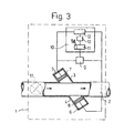
- the connections between the pulse generator 9, the timing means 10 and each of the transceivers 7,8 are switchable such that when the pulse generator 9 is switched to supply electrical pulses to the transceiver 7 the means 10 is switched to receive electrical signals only from the transceiver 8, and vice versa.
Landscapes
- Physics & Mathematics (AREA)
- Electromagnetism (AREA)
- Fluid Mechanics (AREA)
- General Physics & Mathematics (AREA)
- Measuring Volume Flow (AREA)
- Ultra Sonic Daignosis Equipment (AREA)
Claims (9)
- Débitmètre acoustique comprenant des moyens de chronométrage (10) pour déterminer des valeurs de temps de parcours en aval (Td) et en amont (Tu), d'impulsions acoustiques transmises entre des générateurs (7, 8) et des récepteurs (8, 7) de signaux acoustiques, dans le sens d'écoulement du fluide et dans le sens inverse, caractérisé en ce qu'il est, de plus, prévu un indicateur de signal d'erreur (16) conçu pour recevoir les valeurs de temps de parcours (Td, Tu) déterminées et pour émettre un signal d'erreur indicatif d'une fausse lecture de débit, si la somme (Tsomme) des valeurs de temps de parcours en aval et en amont, ou la différence (Tdiff) entre celles-ci, diffère d'une valeur de réglage correspondante (Tc) d'une quantité prédéterminée.
- Débitmètre selon la revendication 1, caractérisé en ce que l'indicateur de signal d'erreur (16) est conçu pour émettre le signal d'erreur en fonction du fait que la somme (Tsomme) des valeurs de temps de parcours en amont (Tu) et en aval (Td) diffère de la valeur de réglage correspondant (Tc).
- Débitmètre selon la revendication 2, caractérisé en ce que la valeur de réglage correspondante (Tc) est formée à partir de la somme des valeurs de temps de parcours déterminées pendant des conditions d'écoulement essentiellement laminaires.
- Débitmètre selon la revendication 3, caractérisé en ce que la valeur de réglage (Tc) est obtenue lorsque le débit est essentiellement nul.
- Débitmètre selon la revendication 1, caractérisé en ce que l'indicateur de signal d'erreur (16) est conçu pour fonctionner à un débit connu et pour émettre le signal d'erreur en fonction du fait que la différence (Tdiff) entre les valeurs de temps de parcours en aval (Td) et en amont (Tu) excède la valeur de réglage correspondante.
- Débitmètre selon la revendication 5, caractérisé en ce que l'indicateur de signal d'erreur est conçu pour fonctionner à un débit nul.
- Débitmètre selon l'une quelconque des revendications précédentes, caractérisé en ce qu'il est, en outre, prévu une vanne (17) conçue pour réguler le débit au-delà des générateurs (7, 8) et récepteurs (8, 7) de signaux acoustiques.
- Débitmètre selon l'une quelconque des revendications précédentes, caractérisé en ce que la valeur de réglage correspondante (Tc) est périodiquement mise à jour au moyen des valeurs de temps de parcours (Tu, Td) déterminées.
- Système d'écoulement de fluide comprenant une conduite dans laquelle un fluide peut s'écouler et un débitmètre disposé de manière à mesurer l'écoulement du fluide dans la conduite, caractérisé en ce que le débitmètre est un débitmètre (1) selon l'une quelconque des revendications précédentes.
Applications Claiming Priority (2)
| Application Number | Priority Date | Filing Date | Title |
|---|---|---|---|
| SE9800074A SE9800074D0 (sv) | 1998-01-15 | 1998-01-15 | Acoustic flow meter |
| SE9800074 | 1998-01-15 |
Publications (3)
| Publication Number | Publication Date |
|---|---|
| EP0932029A2 EP0932029A2 (fr) | 1999-07-28 |
| EP0932029A3 EP0932029A3 (fr) | 1999-09-15 |
| EP0932029B1 true EP0932029B1 (fr) | 2006-09-27 |
Family
ID=20409859
Family Applications (1)
| Application Number | Title | Priority Date | Filing Date |
|---|---|---|---|
| EP98121533A Expired - Lifetime EP0932029B1 (fr) | 1998-01-15 | 1998-11-17 | Débitmètre acoustique |
Country Status (5)
| Country | Link |
|---|---|
| US (1) | US6098467A (fr) |
| EP (1) | EP0932029B1 (fr) |
| JP (1) | JPH11271119A (fr) |
| DE (1) | DE69836002T2 (fr) |
| SE (1) | SE9800074D0 (fr) |
Families Citing this family (13)
| Publication number | Priority date | Publication date | Assignee | Title |
|---|---|---|---|---|
| US7152490B1 (en) | 2005-08-15 | 2006-12-26 | Daniel Measurement And Control, Inc. | Methods for determining transducer delay time and transducer separation in ultrasonic flow meters |
| US7681460B2 (en) * | 2007-04-20 | 2010-03-23 | Gilbarco Inc. | System and method for detecting pressure variations in fuel dispensers to more accurately measure fuel delivered |
| JP2009058444A (ja) * | 2007-08-31 | 2009-03-19 | Institute Of National Colleges Of Technology Japan | 人工呼吸器用流量計 |
| US7725271B2 (en) * | 2007-11-13 | 2010-05-25 | Gilbarco Inc. | Nozzle snap flow compensation |
| US8042376B2 (en) * | 2008-06-02 | 2011-10-25 | Gilbarco Inc. | Fuel dispenser utilizing pressure sensor for theft detection |
| US8494932B2 (en) | 2011-03-18 | 2013-07-23 | International Business Machines Corporation | Fluid flow measurement system |
| US10508937B2 (en) * | 2012-04-12 | 2019-12-17 | Texas Instruments Incorporated | Ultrasonic flow meter |
| DE102012112516A1 (de) * | 2012-12-18 | 2014-06-18 | Endress + Hauser Flowtec Ag | Verfahren zur Verifizierung der Zuverlässigkeit von ermittelten Messdaten einer Ultraschall-Durchflussmessung nach der Laufzeitdifferenz-Methode und Ultraschalldurchflussmessgerät |
| AU2015301406B2 (en) | 2014-08-14 | 2020-07-16 | Reliance Worldwide Corporation | Methods and apparatus for fluid flow monitoring and leak detection |
| MX370819B (es) | 2014-08-14 | 2020-01-08 | Reliance Worldwide Corp | Dispositivos y sistemas para canalización y monitoreo automático de flujo de fluido en sistemas de distribución de fluido. |
| FR3030726A1 (fr) | 2014-12-19 | 2016-06-24 | Gdf Suez | Capteur de debit non intrusif autonome en energie et procede de conversion d'energie thermique en energie electrique sur un reseau de transport de fluides mettant en œuvre un tel capteur |
| US9714855B2 (en) | 2015-01-26 | 2017-07-25 | Arad Ltd. | Ultrasonic water meter |
| CN110383014B (zh) * | 2017-03-07 | 2022-01-04 | Abb瑞士股份有限公司 | 用于测量管道中流体的流速的设备和方法 |
Family Cites Families (11)
| Publication number | Priority date | Publication date | Assignee | Title |
|---|---|---|---|---|
| US3818757A (en) * | 1972-05-05 | 1974-06-25 | Saratoga Sys Inc | Dual path ultrasonic fluid flow metering system and method |
| US3918304A (en) * | 1973-11-23 | 1975-11-11 | Westinghouse Electric Corp | Flowmeter computer |
| JPS5829854B2 (ja) * | 1977-07-26 | 1983-06-25 | 富士電機株式会社 | 超音波式測定装置 |
| US4271708A (en) * | 1978-05-16 | 1981-06-09 | Fuji Electric Co., Ltd. | Ultrasonic measuring apparatus |
| JPS5827449B2 (ja) * | 1978-08-09 | 1983-06-09 | 富士電機株式会社 | 超音波伝搬時間検出回路装置 |
| US4345479A (en) * | 1981-01-13 | 1982-08-24 | The Perkin-Elmer Corporation | Flowmeter system with synchronous clock for generation of timing signals |
| JPS59195126A (ja) * | 1983-04-21 | 1984-11-06 | Yokogawa Hokushin Electric Corp | 超音波流量計 |
| US4633719A (en) * | 1985-03-27 | 1987-01-06 | Badger Meter, Inc. | Digital flow meter circuit and method for measuring flow |
| US5247826B1 (en) * | 1992-11-12 | 1995-07-18 | Devilbiss Health Care Inc | Gas concentration and/or flow sensor |
| DE4318690A1 (de) * | 1993-06-04 | 1995-01-05 | Ndd Medizintechnik Gmbh | Verfahren zur Messung der Molmasse von Gasen oder Gasgemischen und Vorrichtung zur Durchführung dieses Verfahrens |
| US5463906A (en) * | 1994-01-24 | 1995-11-07 | Triton Technology, Inc. | Interchangeable disposable acoustic for use with an ultrasonic flowmeter, particularly during extracorporeal measurement of blood flow |
-
1998
- 1998-01-15 SE SE9800074A patent/SE9800074D0/xx unknown
- 1998-11-17 DE DE69836002T patent/DE69836002T2/de not_active Expired - Lifetime
- 1998-11-17 EP EP98121533A patent/EP0932029B1/fr not_active Expired - Lifetime
- 1998-12-15 US US09/210,832 patent/US6098467A/en not_active Expired - Lifetime
-
1999
- 1999-01-14 JP JP11007934A patent/JPH11271119A/ja active Pending
Also Published As
| Publication number | Publication date |
|---|---|
| DE69836002T2 (de) | 2007-05-16 |
| DE69836002D1 (de) | 2006-11-09 |
| EP0932029A3 (fr) | 1999-09-15 |
| JPH11271119A (ja) | 1999-10-05 |
| US6098467A (en) | 2000-08-08 |
| EP0932029A2 (fr) | 1999-07-28 |
| SE9800074D0 (sv) | 1998-01-15 |
Similar Documents
| Publication | Publication Date | Title |
|---|---|---|
| EP0932029B1 (fr) | Débitmètre acoustique | |
| US8700344B2 (en) | Ultrasonic flow meter | |
| US7073395B2 (en) | Ultrasonic flowmeter and ultrasonic flow rate measuring method | |
| TWI386629B (zh) | Flow measurement device | |
| JPH06148003A (ja) | 超音波を用いた温度測定装置 | |
| JP3562712B2 (ja) | 流量計測装置 | |
| EP0981201B1 (fr) | Détecteur de passages par zéro puis procédé de détermination d'une valeur de passage par zéro | |
| JP4673950B2 (ja) | 超音波式ガス流量計測部の異常診断装置、及び該異常診断装置を備えた超音波式ガスメータ | |
| JPWO2000070312A1 (ja) | 流量計測装置 | |
| EP1231456B1 (fr) | Dispositif et méthode pour déterminer, par voie acoustique, la température d'un fluide | |
| EP3321644A1 (fr) | Unité de surveillance d'écoulement de fluide | |
| JP4792653B2 (ja) | 流量計 | |
| JP4082246B2 (ja) | 流量計 | |
| JP6405520B2 (ja) | 超音波流量計 | |
| JP4760115B2 (ja) | 流体の流れ計測装置 | |
| JP3443658B2 (ja) | 流量計測装置 | |
| JP5229349B2 (ja) | 流体の流れ計測装置 | |
| JP2000074719A (ja) | 推量式流量計 | |
| JP4813649B2 (ja) | ガス遮断装置 | |
| JP2004085421A (ja) | 超音波流量計 | |
| JP2003344124A (ja) | 流量計 | |
| JP4163887B2 (ja) | 流量計 | |
| JP4390350B2 (ja) | ガスメーター | |
| JPH0336889Y2 (fr) | ||
| JPS5870132A (ja) | 超音波流量計 |
Legal Events
| Date | Code | Title | Description |
|---|---|---|---|
| PUAI | Public reference made under article 153(3) epc to a published international application that has entered the european phase |
Free format text: ORIGINAL CODE: 0009012 |
|
| AK | Designated contracting states |
Kind code of ref document: A2 Designated state(s): DE FR SE |
|
| AX | Request for extension of the european patent |
Free format text: AL;LT;LV;MK;RO;SI |
|
| PUAL | Search report despatched |
Free format text: ORIGINAL CODE: 0009013 |
|
| AK | Designated contracting states |
Kind code of ref document: A3 Designated state(s): AT BE CH CY DE DK ES FI FR GB GR IE IT LI LU MC NL PT SE |
|
| AX | Request for extension of the european patent |
Free format text: AL;LT;LV;MK;RO;SI |
|
| 17P | Request for examination filed |
Effective date: 20000121 |
|
| AKX | Designation fees paid |
Free format text: DE FR SE |
|
| RAP1 | Party data changed (applicant data changed or rights of an application transferred) |
Owner name: MAQUET CRITICAL CARE AB |
|
| GRAP | Despatch of communication of intention to grant a patent |
Free format text: ORIGINAL CODE: EPIDOSNIGR1 |
|
| RIN1 | Information on inventor provided before grant (corrected) |
Inventor name: WALLEN, LARS |
|
| GRAS | Grant fee paid |
Free format text: ORIGINAL CODE: EPIDOSNIGR3 |
|
| GRAA | (expected) grant |
Free format text: ORIGINAL CODE: 0009210 |
|
| AK | Designated contracting states |
Kind code of ref document: B1 Designated state(s): DE FR SE |
|
| REF | Corresponds to: |
Ref document number: 69836002 Country of ref document: DE Date of ref document: 20061109 Kind code of ref document: P |
|
| PG25 | Lapsed in a contracting state [announced via postgrant information from national office to epo] |
Ref country code: SE Free format text: LAPSE BECAUSE OF FAILURE TO SUBMIT A TRANSLATION OF THE DESCRIPTION OR TO PAY THE FEE WITHIN THE PRESCRIBED TIME-LIMIT Effective date: 20061227 |
|
| ET | Fr: translation filed | ||
| PLBE | No opposition filed within time limit |
Free format text: ORIGINAL CODE: 0009261 |
|
| STAA | Information on the status of an ep patent application or granted ep patent |
Free format text: STATUS: NO OPPOSITION FILED WITHIN TIME LIMIT |
|
| 26N | No opposition filed |
Effective date: 20070628 |
|
| REG | Reference to a national code |
Ref country code: DE Ref legal event code: R082 Ref document number: 69836002 Country of ref document: DE Representative=s name: SCHAUMBURG UND PARTNER PATENTANWAELTE MBB, DE Ref country code: DE Ref legal event code: R082 Ref document number: 69836002 Country of ref document: DE Representative=s name: SCHAUMBURG & PARTNER PATENTANWAELTE MBB, DE Ref country code: DE Ref legal event code: R082 Ref document number: 69836002 Country of ref document: DE Representative=s name: SCHAUMBURG & PARTNER PATENTANWAELTE GBR, DE |
|
| REG | Reference to a national code |
Ref country code: FR Ref legal event code: PLFP Year of fee payment: 18 |
|
| PGFP | Annual fee paid to national office [announced via postgrant information from national office to epo] |
Ref country code: DE Payment date: 20151110 Year of fee payment: 18 |
|
| PGFP | Annual fee paid to national office [announced via postgrant information from national office to epo] |
Ref country code: FR Payment date: 20151008 Year of fee payment: 18 |
|
| REG | Reference to a national code |
Ref country code: DE Ref legal event code: R119 Ref document number: 69836002 Country of ref document: DE |
|
| REG | Reference to a national code |
Ref country code: FR Ref legal event code: ST Effective date: 20170731 |
|
| PG25 | Lapsed in a contracting state [announced via postgrant information from national office to epo] |
Ref country code: FR Free format text: LAPSE BECAUSE OF NON-PAYMENT OF DUE FEES Effective date: 20161130 |
|
| PG25 | Lapsed in a contracting state [announced via postgrant information from national office to epo] |
Ref country code: DE Free format text: LAPSE BECAUSE OF NON-PAYMENT OF DUE FEES Effective date: 20170601 |