EP0932061B1 - Composant optique ayant un film magnétique mince pour orientation et assemblage - Google Patents
Composant optique ayant un film magnétique mince pour orientation et assemblage Download PDFInfo
- Publication number
- EP0932061B1 EP0932061B1 EP99300343A EP99300343A EP0932061B1 EP 0932061 B1 EP0932061 B1 EP 0932061B1 EP 99300343 A EP99300343 A EP 99300343A EP 99300343 A EP99300343 A EP 99300343A EP 0932061 B1 EP0932061 B1 EP 0932061B1
- Authority
- EP
- European Patent Office
- Prior art keywords
- component
- magnetic material
- optical component
- layer
- film
- Prior art date
- Legal status (The legal status is an assumption and is not a legal conclusion. Google has not performed a legal analysis and makes no representation as to the accuracy of the status listed.)
- Expired - Lifetime
Links
- 230000003287 optical effect Effects 0.000 title claims description 57
- 230000005291 magnetic effect Effects 0.000 title claims description 47
- 239000010409 thin film Substances 0.000 title claims description 23
- 239000010410 layer Substances 0.000 claims description 59
- 239000000696 magnetic material Substances 0.000 claims description 26
- 238000000034 method Methods 0.000 claims description 24
- 239000010408 film Substances 0.000 claims description 21
- 238000005476 soldering Methods 0.000 claims description 21
- 239000000463 material Substances 0.000 claims description 18
- BASFCYQUMIYNBI-UHFFFAOYSA-N platinum Chemical compound [Pt] BASFCYQUMIYNBI-UHFFFAOYSA-N 0.000 claims description 18
- 239000000758 substrate Substances 0.000 claims description 14
- 230000004888 barrier function Effects 0.000 claims description 13
- KDLHZDBZIXYQEI-UHFFFAOYSA-N Palladium Chemical compound [Pd] KDLHZDBZIXYQEI-UHFFFAOYSA-N 0.000 claims description 9
- 229910017052 cobalt Inorganic materials 0.000 claims description 9
- 239000010941 cobalt Substances 0.000 claims description 9
- GUTLYIVDDKVIGB-UHFFFAOYSA-N cobalt atom Chemical compound [Co] GUTLYIVDDKVIGB-UHFFFAOYSA-N 0.000 claims description 9
- PCHJSUWPFVWCPO-UHFFFAOYSA-N gold Chemical compound [Au] PCHJSUWPFVWCPO-UHFFFAOYSA-N 0.000 claims description 9
- 229910052737 gold Inorganic materials 0.000 claims description 9
- 239000010931 gold Substances 0.000 claims description 9
- 229910052697 platinum Inorganic materials 0.000 claims description 9
- 229910000679 solder Inorganic materials 0.000 claims description 9
- 229910052751 metal Inorganic materials 0.000 claims description 8
- 230000005540 biological transmission Effects 0.000 claims description 7
- 239000002184 metal Substances 0.000 claims description 7
- ATJFFYVFTNAWJD-UHFFFAOYSA-N Tin Chemical compound [Sn] ATJFFYVFTNAWJD-UHFFFAOYSA-N 0.000 claims description 6
- RTAQQCXQSZGOHL-UHFFFAOYSA-N Titanium Chemical compound [Ti] RTAQQCXQSZGOHL-UHFFFAOYSA-N 0.000 claims description 6
- 239000012790 adhesive layer Substances 0.000 claims description 6
- 239000011135 tin Substances 0.000 claims description 6
- 229910052718 tin Inorganic materials 0.000 claims description 6
- 239000010936 titanium Substances 0.000 claims description 6
- 229910052719 titanium Inorganic materials 0.000 claims description 6
- 238000004891 communication Methods 0.000 claims description 4
- 229910052763 palladium Inorganic materials 0.000 claims description 4
- 230000035515 penetration Effects 0.000 claims description 4
- 238000007906 compression Methods 0.000 claims description 2
- 239000011133 lead Substances 0.000 claims description 2
- 230000001902 propagating effect Effects 0.000 claims description 2
- 230000004044 response Effects 0.000 claims description 2
- 229910052703 rhodium Inorganic materials 0.000 claims 2
- 239000010948 rhodium Substances 0.000 claims 2
- MHOVAHRLVXNVSD-UHFFFAOYSA-N rhodium atom Chemical compound [Rh] MHOVAHRLVXNVSD-UHFFFAOYSA-N 0.000 claims 2
- 230000003213 activating effect Effects 0.000 claims 1
- 235000012431 wafers Nutrition 0.000 description 9
- PXHVJJICTQNCMI-UHFFFAOYSA-N Nickel Chemical compound [Ni] PXHVJJICTQNCMI-UHFFFAOYSA-N 0.000 description 8
- XEEYBQQBJWHFJM-UHFFFAOYSA-N Iron Chemical compound [Fe] XEEYBQQBJWHFJM-UHFFFAOYSA-N 0.000 description 7
- 238000000151 deposition Methods 0.000 description 5
- 229910052710 silicon Inorganic materials 0.000 description 5
- 229910000859 α-Fe Inorganic materials 0.000 description 5
- XUIMIQQOPSSXEZ-UHFFFAOYSA-N Silicon Chemical compound [Si] XUIMIQQOPSSXEZ-UHFFFAOYSA-N 0.000 description 4
- 229910045601 alloy Inorganic materials 0.000 description 4
- 239000000956 alloy Substances 0.000 description 4
- 238000000576 coating method Methods 0.000 description 4
- 229910052759 nickel Inorganic materials 0.000 description 4
- 239000010703 silicon Substances 0.000 description 4
- 239000011248 coating agent Substances 0.000 description 3
- 230000003993 interaction Effects 0.000 description 3
- 229910052742 iron Inorganic materials 0.000 description 3
- 230000008569 process Effects 0.000 description 3
- 229910017104 Fe—Al—Ni—Co Inorganic materials 0.000 description 2
- VYPSYNLAJGMNEJ-UHFFFAOYSA-N Silicium dioxide Chemical compound O=[Si]=O VYPSYNLAJGMNEJ-UHFFFAOYSA-N 0.000 description 2
- GWEVSGVZZGPLCZ-UHFFFAOYSA-N Titan oxide Chemical compound O=[Ti]=O GWEVSGVZZGPLCZ-UHFFFAOYSA-N 0.000 description 2
- 239000000853 adhesive Substances 0.000 description 2
- 230000001070 adhesive effect Effects 0.000 description 2
- 229910000828 alnico Inorganic materials 0.000 description 2
- 230000008021 deposition Effects 0.000 description 2
- 238000005566 electron beam evaporation Methods 0.000 description 2
- 238000005516 engineering process Methods 0.000 description 2
- 238000005530 etching Methods 0.000 description 2
- SZVJSHCCFOBDDC-UHFFFAOYSA-N ferrosoferric oxide Chemical compound O=[Fe]O[Fe]O[Fe]=O SZVJSHCCFOBDDC-UHFFFAOYSA-N 0.000 description 2
- YBMRDBCBODYGJE-UHFFFAOYSA-N germanium dioxide Chemical compound O=[Ge]=O YBMRDBCBODYGJE-UHFFFAOYSA-N 0.000 description 2
- 238000010348 incorporation Methods 0.000 description 2
- 239000000203 mixture Substances 0.000 description 2
- 238000004806 packaging method and process Methods 0.000 description 2
- VYZAMTAEIAYCRO-UHFFFAOYSA-N Chromium Chemical compound [Cr] VYZAMTAEIAYCRO-UHFFFAOYSA-N 0.000 description 1
- RYGMFSIKBFXOCR-UHFFFAOYSA-N Copper Chemical compound [Cu] RYGMFSIKBFXOCR-UHFFFAOYSA-N 0.000 description 1
- 229910017881 Cu—Ni—Fe Inorganic materials 0.000 description 1
- 239000004593 Epoxy Substances 0.000 description 1
- 229910017110 Fe—Cr—Co Inorganic materials 0.000 description 1
- ZOKXTWBITQBERF-UHFFFAOYSA-N Molybdenum Chemical compound [Mo] ZOKXTWBITQBERF-UHFFFAOYSA-N 0.000 description 1
- 229910020220 Pb—Sn Inorganic materials 0.000 description 1
- BQCADISMDOOEFD-UHFFFAOYSA-N Silver Chemical compound [Ag] BQCADISMDOOEFD-UHFFFAOYSA-N 0.000 description 1
- 229910052782 aluminium Inorganic materials 0.000 description 1
- XAGFODPZIPBFFR-UHFFFAOYSA-N aluminium Chemical compound [Al] XAGFODPZIPBFFR-UHFFFAOYSA-N 0.000 description 1
- 230000000712 assembly Effects 0.000 description 1
- 238000000429 assembly Methods 0.000 description 1
- 229910052796 boron Inorganic materials 0.000 description 1
- 229910052804 chromium Inorganic materials 0.000 description 1
- 239000011651 chromium Substances 0.000 description 1
- 229910052681 coesite Inorganic materials 0.000 description 1
- 150000001875 compounds Chemical class 0.000 description 1
- 229910052802 copper Inorganic materials 0.000 description 1
- 239000010949 copper Substances 0.000 description 1
- 229910052906 cristobalite Inorganic materials 0.000 description 1
- 229910000777 cunife Inorganic materials 0.000 description 1
- 230000003247 decreasing effect Effects 0.000 description 1
- 230000007547 defect Effects 0.000 description 1
- 238000010894 electron beam technology Methods 0.000 description 1
- 239000003302 ferromagnetic material Substances 0.000 description 1
- 229910052733 gallium Inorganic materials 0.000 description 1
- 239000002223 garnet Substances 0.000 description 1
- 229910052732 germanium Inorganic materials 0.000 description 1
- 239000011521 glass Substances 0.000 description 1
- 239000007788 liquid Substances 0.000 description 1
- 238000001459 lithography Methods 0.000 description 1
- 238000004519 manufacturing process Methods 0.000 description 1
- 238000001465 metallisation Methods 0.000 description 1
- 229910052750 molybdenum Inorganic materials 0.000 description 1
- 239000011733 molybdenum Substances 0.000 description 1
- 229910001172 neodymium magnet Inorganic materials 0.000 description 1
- 239000013307 optical fiber Substances 0.000 description 1
- 230000005693 optoelectronics Effects 0.000 description 1
- 239000011368 organic material Substances 0.000 description 1
- TWNQGVIAIRXVLR-UHFFFAOYSA-N oxo(oxoalumanyloxy)alumane Chemical compound O=[Al]O[Al]=O TWNQGVIAIRXVLR-UHFFFAOYSA-N 0.000 description 1
- 229910052698 phosphorus Inorganic materials 0.000 description 1
- 229910052761 rare earth metal Inorganic materials 0.000 description 1
- 150000002910 rare earth metals Chemical class 0.000 description 1
- 239000000377 silicon dioxide Substances 0.000 description 1
- 229910052709 silver Inorganic materials 0.000 description 1
- 239000004332 silver Substances 0.000 description 1
- 238000004544 sputter deposition Methods 0.000 description 1
- 229910052682 stishovite Inorganic materials 0.000 description 1
- 238000000427 thin-film deposition Methods 0.000 description 1
- 229910052723 transition metal Inorganic materials 0.000 description 1
- 150000003624 transition metals Chemical class 0.000 description 1
- 229910052905 tridymite Inorganic materials 0.000 description 1
- 229910000586 vicalloy Inorganic materials 0.000 description 1
Images


Classifications
-
- G—PHYSICS
- G02—OPTICS
- G02B—OPTICAL ELEMENTS, SYSTEMS OR APPARATUS
- G02B6/00—Light guides; Structural details of arrangements comprising light guides and other optical elements, e.g. couplings
- G02B6/24—Coupling light guides
- G02B6/36—Mechanical coupling means
- G02B6/3628—Mechanical coupling means for mounting fibres to supporting carriers
-
- G—PHYSICS
- G02—OPTICS
- G02B—OPTICAL ELEMENTS, SYSTEMS OR APPARATUS
- G02B27/00—Optical systems or apparatus not provided for by any of the groups G02B1/00 - G02B26/00, G02B30/00
- G02B27/62—Optical apparatus specially adapted for adjusting optical elements during the assembly of optical systems
-
- G—PHYSICS
- G02—OPTICS
- G02B—OPTICAL ELEMENTS, SYSTEMS OR APPARATUS
- G02B27/00—Optical systems or apparatus not provided for by any of the groups G02B1/00 - G02B26/00, G02B30/00
- G02B27/64—Imaging systems using optical elements for stabilisation of the lateral and angular position of the image
- G02B27/646—Imaging systems using optical elements for stabilisation of the lateral and angular position of the image compensating for small deviations, e.g. due to vibration or shake
- G02B27/648—Imaging systems using optical elements for stabilisation of the lateral and angular position of the image compensating for small deviations, e.g. due to vibration or shake for automatically maintaining a reference alignment, e.g. in self-levelling surveying instruments
-
- G—PHYSICS
- G02—OPTICS
- G02B—OPTICAL ELEMENTS, SYSTEMS OR APPARATUS
- G02B6/00—Light guides; Structural details of arrangements comprising light guides and other optical elements, e.g. couplings
- G02B6/24—Coupling light guides
- G02B6/42—Coupling light guides with opto-electronic elements
- G02B6/4201—Packages, e.g. shape, construction, internal or external details
- G02B6/4219—Mechanical fixtures for holding or positioning the elements relative to each other in the couplings; Alignment methods for the elements, e.g. measuring or observing methods especially used therefor
- G02B6/422—Active alignment, i.e. moving the elements in response to the detected degree of coupling or position of the elements
- G02B6/4226—Positioning means for moving the elements into alignment, e.g. alignment screws, deformation of the mount
-
- G—PHYSICS
- G02—OPTICS
- G02B—OPTICAL ELEMENTS, SYSTEMS OR APPARATUS
- G02B7/00—Mountings, adjusting means, or light-tight connections, for optical elements
- G02B7/003—Alignment of optical elements
-
- G—PHYSICS
- G02—OPTICS
- G02B—OPTICAL ELEMENTS, SYSTEMS OR APPARATUS
- G02B6/00—Light guides; Structural details of arrangements comprising light guides and other optical elements, e.g. couplings
- G02B6/24—Coupling light guides
- G02B6/36—Mechanical coupling means
- G02B6/3608—Fibre wiring boards, i.e. where fibres are embedded or attached in a pattern on or to a substrate, e.g. flexible sheets
- G02B6/3612—Wiring methods or machines
-
- G—PHYSICS
- G02—OPTICS
- G02B—OPTICAL ELEMENTS, SYSTEMS OR APPARATUS
- G02B6/00—Light guides; Structural details of arrangements comprising light guides and other optical elements, e.g. couplings
- G02B6/24—Coupling light guides
- G02B6/42—Coupling light guides with opto-electronic elements
- G02B6/4201—Packages, e.g. shape, construction, internal or external details
- G02B6/4204—Packages, e.g. shape, construction, internal or external details the coupling comprising intermediate optical elements, e.g. lenses, holograms
Definitions
- the present invention relates to an optical component and more particularly, to an optical component having a magnetic film deposited on a portion of its outer surface for orientating the component with an applied magnetic field.
- the invention further involves methods of assembling optical components involving passive orientation of the components with use of a magnetic film and an applied magnetic field, which is particularly advantageous for assembling spherical and cylindrical optical components.
- optical components need to be firmly attached to a substrate within the path of light.
- Such devices include lasers, p-i-n diodes, and assemblies of such devices with passive elements such as planar waveguides.
- methods for attaching the optical components to a substrate include aluminum oxide (“ALO") bonding, solder bonding, and solder-glass bonding.
- ALO bonding methods present many technical difficulties, including the need for high temperatures and high stress which have a tendency to produce defects such as cracks that can remain hidden for a long time and cause reliability problems.
- Another method of attachment includes epoxy bonding, but this has the disadvantage of relying upon use of organic materials which, when applied to optical components, can promote facet failure or moisture which likewise creates reliability problems.
- Bonding of optical components is further complicated because the components often include objects such as spherical ball and cylindrical lenses which, due to their smooth outer surfaces, are difficult to handle. Soldering of the components requires depositing a metallization layer on their surfaces, which destroys the symmetry of the components and increases handling problems.
- Optical components used in laser communications systems or other systems involving gain media may be required to have specialized asymmetrical coatings on their surfaces for specific purposes, such as the avoidance of circulating rainbow or "whispering gallery" modes of spherical lenses, which can cause excess feedback and self-modulation.
- These asymmetrical components are particularly difficult to handle, as they often must be carefully attached during assembly on a substrate with the asymmetrical feature oriented in a precise alignment relative to the path of light.
- JP-61138201-A discloses a process to execute a non-reflection coating and make possible the incorporation of a spherical lens coated partly with a magnetic material as a single body into a module by attracting the metallic part of said spherical lens into a round recess of a magnet and executing non-reflection coating.
- DE-3719382-A1 discloses the soldering of a optical ball lens into a holder by thermo-compression bonding.
- EP-559364-A1 discloses magnetic holding means wherein an optical fiber is precoated with a magnetic material and then placed in an elongated groove where it may be permanently mounted by soldering or adhesive.
- an optical component and method for attaching the optical component that minimizes difficulties associated with manually, precisely orienting the component.
- this method should exhibit high reliability and be compatible with existing technologies, such as solder bonding or thermocompression, already in use in packaging.
- the instant invention addresses these needs by providing a substantially self-orienting optical component which aids in assembly and methods for assembling a sub-optical assembly comprising passively orienting the component. Further advantages may appear more fully upon consideration of the description given below.
- the invention comprises an optical component having a film of magnetic material deposited on a portion of its outer surface for orientating the component in response to an applied magnetic field.
- the film of magnetic material When a magnetic field is applied adjacent the optical component, the film of magnetic material will respond to the field to induce the component to move to a pre-determined orientation.
- the film of magnetic material is comprised of cobalt, nickel, iron, garnet, or ferrite, or an alloy comprising these materials.
- the optical component also may have further layers deposited on portions of its outer surface for aiding in adhesion, soldering, thermocompression bonding, or light transmission.
- the component has deposited over a portion of its outer surface: first, an adhesive layer comprised of titanium; second, a magnetic thin film layer comprised of cobalt; third, a barrier layer comprised of platinum; and fourth, a soldering layer comprised of one or more layers of material selected from the group consisting of gold and tin.
- Embodiments of the invention also involve methods of assembling an optical subassembly comprising providing an optical component; depositing a film of magnetic material over a portion of the outer surface of the optical component; and applying a magnetic field to the optical component to induce it to move to a pre-determined orientation to aid in positioning it on a submount.
- Embodiments further embrace an optical sub-assembly comprising an optical component having a film of magnetic material bonded to a submount adjacent a laser.
- passive means of orientation may be used in the assembly of optical components so that the components may be properly oriented without use of active or manual means of orientation, thereby reducing the costs of handling and assembly of these components.
- the passive means of orientation involves depositing thin films of magnetic material on a portion of the surface of an optical component, which allows the component to self-orient in the presence of a spatially non-uniform magnetic field.
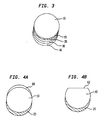
- Figure 1 shows a component in the form of a ball lens 10 having a portion of its surface coated with a magnetic thin film 20.
- Figures 2A and 2B illustrate the self-orientation of this component in the presence of an applied magnetic field.
- the ball lens 10 is shown with its magnetic thin film 20 in a position in the high field region of the non-uniform magnetic field produced by magnet 50.
- the interaction of the magnetic field with the magnetic material may be roughly described as an induced dipole interaction which is characterized by an energy level E1.
- the ball lens 10 is shown with its magnetic thin film 20 in a position in the low field region of the non-uniform magnetic field, characterized by an energy E2.
- the magnetic thin film may comprise any of a large number of ferromagnetic materials, including metallic elements such as cobalt, iron, or nickel or compounds such as garnets or ferrites. Examples of such materials comprise the following alloys and compositions: SmFe 2 ; Fe-20weight %Ni; 70%Co-30%Fe; Fe-30%Cr-15%Co; the Fe-Al-Ni-Co alloy commonly known as Alnico; Fe 3 O 4 ferrite; TbFe 2 and a Th 0.28 Dy 0.72 Fe 2 alloy.
- the film of magnetic material also may comprise one or more layers of such materials, preferably interspersed with one or more layers fabricated with platinum or palladium.
- the orientation can be accomplished by use of a DC electromagnet or a high strength permanent magnet, i.e., 50, fabricated with materials such as Nd-Fe-B or SmCo 5 .
- materials such as Nd-Fe-B or SmCo 5 .
- other materials that may be used to fabricate the magnets include Fe-Cr-Co, Fe-Al-Ni-Co (Alnico), Cu-Ni-Fe (Cunife), Co-Fe-V (Vicalloy), specially-processed, low-coercivity (H c ), rare earth cobalt (Sm-Co), or magnets comprising Ba-ferrite or Sr-ferrite.
- This passive means of orientation may be used with highly symmetrical piece parts (e.g., ball or cylindrical lenses), is compatible with readily-available and reliable means of assembly (e.g., solder bonding), and enables incorporation of asymmetric features in the fabrication of the components.
- the magnetic thin film may be incorporated as one layer of a multilayer structure, with the multilayer structure comprising layers designed to achieve specific functions beyond orienting the structure, such as bonding the component to a substrate, adhering the layers together, or aiding in transmission of light rays passing through the component.
- Figure 3 shows the ball lens 10 having a multilayer structure disposed thereon.
- an adhesive layer 15 is provided for securing the magnetic material to the outer surface of the component;
- the magnetic thin film layer 20 is provided for passively orienting the lens;
- a barrier layer 30 is provided for controlling penetration of a solder;
- a soldering layer is provided over a portion of the exterior surface of the component for bonding the component to a substrate.
- the adhesive layer comprises a film of titanium in an approximate thickness of 500 Angstroms ( ⁇ );
- the magnetic layer comprises a film of cobalt having an approximate thickness of 5,000 ⁇ ;
- the barrier layer comprises a film of platinum having an approximate thickness of 2,000 ⁇ ;
- the soldering layer comprises a layer of gold having an approximate thickness of 2,000 ⁇ .
- the titanium provides good adhesion of the metal film to the lens;
- the cobalt provides magnetic functionality;
- the platinum provides a good barrier to solder penetration; and the gold provides a clean, solderable surface.
- the adhesive layer may be comprised of chromium or molybdenum.
- the barrier layer advantageously may be comprised of a transition metal such as iron (Fe), nickel (Ni), cobalt (Co), or palladium (Pd).
- the soldering layer 40 of Figure 3 may itself comprise a multilayer structure, e.g., alternating layers of gold, tin, and gold are advantageous, or alternating layers of lead and tin (Pb-Sn) may be used.
- Advantageous materials for use in the soldering of optical components are further described in U.S. Pat. application serial no.
- one or more layers of ductile metal may be deposited over a portion of the exterior surface of the component for thermocompression bonding of the component to a substrate.
- the optical component also may incorporate an additional thin film transmission layer 60 or removed section 62 antipodal to the magnetic thin film, as shown in Figures 4A and 4B , respectively, which serve a light-leak function.
- the transmission layer 60 is fabricated with a material having an index of refraction higher than the index of refraction of the material comprising the lens 10. In this way, light rays propagating along the surface of the lens will escape from, or be transmitted from, the lens.
- Exemplary materials for fabricating the transmission layer comprise TiO 2 , Si, Ge, or SiO 2 doped with GeO 2 or one or more of Ge, Al, B, P, Ga, or La to raise the refractive index of the material.
- the removed 62 layer allows for escape of surface-propagating rays. Standard etching techniques (liquid or plasma), may be used to remove the material.
- soldering or transmission layers may be precisely aligned on a substrate by selective deposition of the magnetic layer, without having to manually or actively position the parts during assembly.
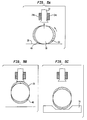
- Figures 5A, 5B, and 5C illustrate one aspect of the assembly process involving use of a pick-up tool 22 having energized coils 24a, 24b.
- the component has a magnetic thin film layer 20 deposited on one portion of its outer surface and an antipodally-disposed soldering layer 40.
- the component is first placed on a flat surface 36 in the presence of a spatially-non-uniform magnetic field and agitated to provide sufficient energy to move it into orientation, as illustrated schematically in Fig. 5A ; the component may need to be vibrated or rolled to provide sufficient kinetic energy to orient the component.
- the component is then picked from the surface using a pickup tool 22, as schematically illustrated in Fig. 5B .
- the head of the pickup tool 22 has energized coils 24a, 24b or magnets attached to it so that the tool provides the magnetic field to orient the component, and the magnetic thin film itself acts as the handle of the component.
- the component is orientated into proper position and the tool simply picks up the component while in correct orientation.
- the component is then placed in position over the substrate 70, the magnetic field generated by the coils 24a, 24b is deactivated, and the component is released from the tool into position on the substrate for bonding.
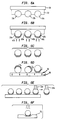
- Coating of the magnetic thin film layer may be accomplished with use of a removable medium, as illustrated in Figs. 6A-6F .
- Optical components 10a, 10b, 10c are first partially embedded in a removable medium 32, such as wax, secured to a plate 34 for stability, as shown in Fig. 6A .
- a portion of the outer surface of the optical components remains exposed.
- Thin films of magnetic material 20a, 20b, and 20c, and soldering layers 40a, 40b, and 40c, are next deposited over the exposed portions of the optical components, as shown in Fig. 6B .
- This deposition of the materials may be accomplished by means well-known to those skilled in the art of thin-film deposition, such as sputtering or electron-beam evaporation.
- the optical components are removed from the medium 32.
- the components are next placed on a flat surface 36, agitated, and oriented into alignment by an applied magnetic field 50.
- a pick-up tool 22a is used to remove the components from the surface 36 and place them in position on a substrate 70, as shown in Fig. 6E .
- the pick-up tool 22a in this embodiment comprises a vacuum pick-up tool.
- the component is placed in position on the substrate, released from the tool 22a, and bonded.
- the optical component 10 is placed in a frame 80 comprised of silicon wafers 80a, 80b, adjacent a plate 80c.
- a frame 80 comprised of silicon wafers 80a, 80b, adjacent a plate 80c.
- two pairs of silicon wafers may be disposed on either side of the component (not shown).
- a square cross-sectional hole in a wafer is used for the frame when the component comprises a ball lens
- a trough cross-sectional hole in a wafer is used when the component comprises a cylindrical lens.
- a single wafer having many holes may be used as a frame to hold a large plurality of components as schematically illustrated in Figs.
- FIG. 7B and 7C which reflect a cross-sectional cut-away view and a top view, respectively, of a plurality of ball lenses 10a, 10b, 10c, held in a silicon wafer frame 88 having square cross-sectional holes.
- Lithography and etching techniques that may be used to produce the wafer holes are well-known to those skilled in the art.
- the component as situated in the frame 80 is secured within a vacuum chamber 82 and the thin film of magnetic material is deposited over the exposed surface.
- Metal vapor may be produced from a pot source of material 85 by electron-beam bombardment generated by an electron gun 87.
- Fig. 8 schematically illustrates a cross-sectional view of an optical sub-assembly comprising a laser 100 on a submount 90 with a ball lens 10 having a magnetic film 20 which is attached to the submount 90 by means of a solder bond 48.
Landscapes
- Physics & Mathematics (AREA)
- General Physics & Mathematics (AREA)
- Optics & Photonics (AREA)
- Optical Couplings Of Light Guides (AREA)
- Semiconductor Lasers (AREA)
- Light Receiving Elements (AREA)
- Mounting And Adjusting Of Optical Elements (AREA)
- Lens Barrels (AREA)
- Thin Magnetic Films (AREA)
Claims (10)
- Composant optique ayant un film de matériau magnétique (20) déposé sur une partie de sa surface extérieure dont la configuration permet d'orienter le composant selon une orientation prédéterminée en réponse à un champ magnétique appliqué de manière adjacente au composant optique, le composant comportant par ailleurs une couche de soudure (40) disposée sur le film de matériau magnétique (20) de sorte que le matériau magnétique est pris en sandwich entre le composant optique et la couche de soudure ;
CARACTÉRISÉ EN CE QUE :le composant optique comporte une lentille sphérique (10) ayant, aux antipodes du film magnétique et de la couche de soudure sus-jacente, une couche de transmission de film mince supplémentaire (60) ou une section retirée pour permettre aux rayons lumineux se propageant le long de la surface de la lentille de s'échapper. - Composant selon la revendication 1, comportant par ailleurs une couche de métal ductile déposée sur une partie de la surface extérieure de la lentille à des fins de soudage par thermocompression de la lentille sur un substrat.
- Composant selon l'une quelconque des revendications précédentes, comportant par ailleurs une couche d'arrêt disposée sur la surface de la couche de soudure pour contrôler la pénétration de la soudure tendre.
- Composant selon l'une quelconque des revendications précédentes, dans lequel la couche de soudure comporte une ou plusieurs couches de matériaux sélectionnés dans le groupe constitué par l'or, le plomb, l'étain et le platine.
- Composant selon les revendications 3 à 4, dans lequel la couche d'arrêt est fabriquée à partir d'un métal sélectionné dans le groupe constitué par le platine, le palladium et le rhodium.
- Composant selon l'une quelconque des revendications précédentes, dans lequel le matériau magnétique comporte du cobalt, et comporte par ailleurs une couche adhésive constituée de titane prise en sandwich entre le composant optique et le film de matériau magnétique à des fins d'assujettissement du matériau magnétique sur la surface extérieure du composant ; une couche d'arrêt constituée de platine disposée sur du matériau magnétique ; et une couche de soudure constituée d'une ou de plusieurs couches d'or ou d'étain disposées sur la couche d'arrêt à des fins de soudage du composant sur un substrat.
- Composant selon la revendication 1, comportant par ailleurs une couche d'arrêt disposée sur la surface de la couche de soudure pour contrôler la pénétration de la soudure tendre, ladite couche d'arrêt étant par exemple fabriquée à partir d'un métal sélectionné dans le groupe constitué par le platine, le palladium et le rhodium.
- Composant selon l'une quelconque des revendications précédentes, dans lequel le matériau magnétique comporte du cobalt et comportant par ailleurs une couche adhésive constituée de titane prise en sandwich entre le composant optique et le film de matériau magnétique à des fins d'assujettissement du matériau magnétique sur la surface extérieure du composant ; une couche d'arrêt constituée de platine disposée sur le matériau magnétique ; et une couche de soudure constituée d'une ou de plusieurs couches d'or ou d'étain disposées sur la couche d'arrêt à des fins de soudage du composant sur un substrat.
- Procédé permettant d'assembler un composant d'un système de communication, comportant les étapes consistant à :mettre en oeuvre un composant optique selon la revendication 1 ;appliquer un champ magnétique sur le composant optique de sorte que le champ magnétique en coopération avec le film de matériau magnétique amène le composant optique à se déplacer selon une orientation prédéterminée ;mettre le film de matériau magnétique en contact avec un électroaimant et activer l'électroaimant pour entraîner le composant à adhérer sur l'électroaimant ;déplacer l'électroaimant et le composant optique attaché de manière adjacente à un emplacement prédéterminé sur une embase ; etdésactiver l'électroaimant pour libérer le composant optique sur l'embase.
- Système de communication comportant le composant selon l'une quelconque des revendications 1 à 8.
Applications Claiming Priority (2)
| Application Number | Priority Date | Filing Date | Title |
|---|---|---|---|
| US09/012,622 US5995293A (en) | 1998-01-23 | 1998-01-23 | Optical components having magnetic thin films for orientation and method of assembling same |
| US12622 | 1998-01-23 |
Publications (3)
| Publication Number | Publication Date |
|---|---|
| EP0932061A2 EP0932061A2 (fr) | 1999-07-28 |
| EP0932061A3 EP0932061A3 (fr) | 2000-08-02 |
| EP0932061B1 true EP0932061B1 (fr) | 2011-03-02 |
Family
ID=21755861
Family Applications (1)
| Application Number | Title | Priority Date | Filing Date |
|---|---|---|---|
| EP99300343A Expired - Lifetime EP0932061B1 (fr) | 1998-01-23 | 1999-01-19 | Composant optique ayant un film magnétique mince pour orientation et assemblage |
Country Status (4)
| Country | Link |
|---|---|
| US (1) | US5995293A (fr) |
| EP (1) | EP0932061B1 (fr) |
| JP (1) | JP3387843B2 (fr) |
| DE (1) | DE69943232D1 (fr) |
Families Citing this family (15)
| Publication number | Priority date | Publication date | Assignee | Title |
|---|---|---|---|---|
| US6548176B1 (en) | 1997-04-03 | 2003-04-15 | The Board Of Trustees Of The Leland Stanford Junior University | Hydroxide-catalyzed bonding |
| JP2907202B1 (ja) * | 1998-02-20 | 1999-06-21 | 住友電気工業株式会社 | 光モジュールの製造方法 |
| DE19927816A1 (de) * | 1999-06-18 | 2001-01-04 | Winter & Ibe Olympus | Endoskop mit verstellbarem Bauelement |
| JP2003026451A (ja) * | 2001-07-16 | 2003-01-29 | Nippon Electric Glass Co Ltd | 光学レンズ |
| EP1327899A1 (fr) * | 2002-01-07 | 2003-07-16 | Alcatel | Un procédé de fabrication d'un module optique et un module optique |
| DE102004034718A1 (de) * | 2004-07-17 | 2005-10-13 | Carl Zeiss Smt Ag | Kittglied für ein optisches Element |
| DE102005019716A1 (de) * | 2005-04-28 | 2006-11-02 | Carl Zeiss Smt Ag | Optisches System mit einem optischen Element |
| US7678458B2 (en) * | 2007-01-24 | 2010-03-16 | Asml Holding N.V. | Bonding silicon silicon carbide to glass ceramics |
| JP4472023B1 (ja) * | 2009-12-11 | 2010-06-02 | 有限会社ナプラ | 電子デバイス用基板、電子デバイス用積層体、電子デバイス及びそれらの製造方法 |
| US9028153B2 (en) * | 2011-10-27 | 2015-05-12 | Tyco Electronics Corporation | Optical fiber having core-to-core alignment |
| US9272371B2 (en) | 2013-05-30 | 2016-03-01 | Agc Automotive Americas R&D, Inc. | Solder joint for an electrical conductor and a window pane including same |
| CN104965311B (zh) * | 2015-07-21 | 2017-07-18 | 哈尔滨理工大学 | 基于磁力吸附的小口径长镜筒光学镜头镜片安装工具 |
| US10263362B2 (en) | 2017-03-29 | 2019-04-16 | Agc Automotive Americas R&D, Inc. | Fluidically sealed enclosure for window electrical connections |
| US10849192B2 (en) | 2017-04-26 | 2020-11-24 | Agc Automotive Americas R&D, Inc. | Enclosure assembly for window electrical connections |
| CN114734395B (zh) * | 2022-06-08 | 2022-08-23 | 中科院南京天文仪器有限公司 | 基于磁气复合吸附的大口径光学镜片安装装置及方法 |
Citations (1)
| Publication number | Priority date | Publication date | Assignee | Title |
|---|---|---|---|---|
| EP0559364A1 (fr) * | 1992-03-02 | 1993-09-08 | Motorola, Inc. | Méthodes de fixation magnétique pour dispositif entrée/sortie des fibres optiques |
Family Cites Families (8)
| Publication number | Priority date | Publication date | Assignee | Title |
|---|---|---|---|---|
| US4553816A (en) * | 1980-12-15 | 1985-11-19 | Honeywell Inc. | Tunable Fabry-Perot filter |
| US4645116A (en) * | 1982-10-08 | 1987-02-24 | At&T Bell Laboratories | Fluxless bonding of microelectronic chips |
| JPS61138201A (ja) * | 1984-12-11 | 1986-06-25 | Matsushita Electric Ind Co Ltd | 無反射コ−テイング膜を有する球レンズの製造法 |
| DE3534366A1 (de) * | 1985-09-26 | 1987-04-02 | Siemens Ag | Verfahren zur unloesbaren befestigung von optischen elementen in einem metallischen traeger sowie haltevorrichtung fuer kugellinsen oder lichtwellenleiter |
| DE3719382A1 (de) * | 1987-06-05 | 1988-12-22 | Siemens Ag | Verfahren zum einsetzen eines optischen bauelements in eine aufnahmebohrung eines tragkoerpers |
| US5249733A (en) * | 1992-07-16 | 1993-10-05 | At&T Bell Laboratories | Solder self-alignment methods |
| US5426412A (en) * | 1992-10-27 | 1995-06-20 | Matsushita Electric Works, Ltd. | Infrared detecting device and infrared detecting element for use in the device |
| JP3352790B2 (ja) * | 1993-11-01 | 2002-12-03 | ▲桜▼井精技株式会社 | 眼内レンズの焦点位置調整方法とその装置 |
-
1998
- 1998-01-23 US US09/012,622 patent/US5995293A/en not_active Expired - Lifetime
-
1999
- 1999-01-19 DE DE69943232T patent/DE69943232D1/de not_active Expired - Lifetime
- 1999-01-19 EP EP99300343A patent/EP0932061B1/fr not_active Expired - Lifetime
- 1999-01-22 JP JP01392699A patent/JP3387843B2/ja not_active Expired - Fee Related
Patent Citations (1)
| Publication number | Priority date | Publication date | Assignee | Title |
|---|---|---|---|---|
| EP0559364A1 (fr) * | 1992-03-02 | 1993-09-08 | Motorola, Inc. | Méthodes de fixation magnétique pour dispositif entrée/sortie des fibres optiques |
Also Published As
| Publication number | Publication date |
|---|---|
| JPH11266059A (ja) | 1999-09-28 |
| EP0932061A2 (fr) | 1999-07-28 |
| EP0932061A3 (fr) | 2000-08-02 |
| JP3387843B2 (ja) | 2003-03-17 |
| US5995293A (en) | 1999-11-30 |
| DE69943232D1 (de) | 2011-04-14 |
Similar Documents
| Publication | Publication Date | Title |
|---|---|---|
| EP0932061B1 (fr) | Composant optique ayant un film magnétique mince pour orientation et assemblage | |
| US6894823B2 (en) | Magnetically actuated microelectromechanical devices and method of manufacture | |
| JP2002236266A (ja) | 磁気的にパッケージされた光memデバイス及びその作製方法 | |
| JP3924104B2 (ja) | 光ファイバ付きフェルール接続型光アイソレータ | |
| US6395126B1 (en) | Method of micro-fabrication | |
| US6181864B1 (en) | Optical fiber array module using soldering and fabrication method thereof | |
| JP2004046059A (ja) | 光スイッチとその製造方法 | |
| US5161049A (en) | Optical isolator and method for preparing same | |
| CN1184507C (zh) | 光学隔离器 | |
| JPH09325299A (ja) | 光アイソレータ付き光ファイバ端子及びこれを用いた半導体レーザモジュール | |
| EP1150840A1 (fr) | Procede de micro-fabrication | |
| US20020124375A1 (en) | Manufacturing system using solder self-alignment with optical component deformation fine alignment | |
| JPH10227996A (ja) | 光アイソレータ | |
| JP3187705B2 (ja) | 光モジュールの製造方法 | |
| US20060022784A1 (en) | Microtechnological device comprising magnetically assembled structures and assembly process | |
| JP2003075679A (ja) | 光アイソレータ付きレセプタクルとその組立方法 | |
| US20090059340A1 (en) | Deformable mirror | |
| US6681473B1 (en) | Method and apparatus for hermetically sealing fiber array blocks | |
| JP2967157B2 (ja) | 光アイソレータ | |
| US12422701B2 (en) | Faraday rotator ball lens | |
| JP4491530B2 (ja) | 光アイソレータ | |
| CN1157627C (zh) | 光学部件及其制造方法 | |
| WO2004010165A2 (fr) | Ensemble optique et son procede de fabrication | |
| JP4628054B2 (ja) | 光アイソレータ | |
| KR20060104264A (ko) | 광학 요소와 광도파로 간의 정렬을 위한 광학 구조물 및 그정렬 방법 |
Legal Events
| Date | Code | Title | Description |
|---|---|---|---|
| PUAI | Public reference made under article 153(3) epc to a published international application that has entered the european phase |
Free format text: ORIGINAL CODE: 0009012 |
|
| AK | Designated contracting states |
Kind code of ref document: A2 Designated state(s): DE FR GB |
|
| AX | Request for extension of the european patent |
Free format text: AL;LT;LV;MK;RO;SI |
|
| PUAL | Search report despatched |
Free format text: ORIGINAL CODE: 0009013 |
|
| AK | Designated contracting states |
Kind code of ref document: A3 Designated state(s): AT BE CH CY DE DK ES FI FR GB GR IE IT LI LU MC NL PT SE |
|
| AX | Request for extension of the european patent |
Free format text: AL;LT;LV;MK;RO;SI |
|
| 17P | Request for examination filed |
Effective date: 20010119 |
|
| AKX | Designation fees paid |
Free format text: DE FR GB |
|
| 17Q | First examination report despatched |
Effective date: 20040907 |
|
| 17Q | First examination report despatched |
Effective date: 20040907 |
|
| RAP3 | Party data changed (applicant data changed or rights of an application transferred) |
Owner name: LUCENT TECHNOLOGIES INC. |
|
| RTI1 | Title (correction) |
Free format text: OPTICAL COMPONENT HAVING MAGNETIC THIN FILM FOR ORIENTATION AND ASSEMBLY |
|
| GRAP | Despatch of communication of intention to grant a patent |
Free format text: ORIGINAL CODE: EPIDOSNIGR1 |
|
| GRAS | Grant fee paid |
Free format text: ORIGINAL CODE: EPIDOSNIGR3 |
|
| GRAA | (expected) grant |
Free format text: ORIGINAL CODE: 0009210 |
|
| AK | Designated contracting states |
Kind code of ref document: B1 Designated state(s): DE FR GB |
|
| REG | Reference to a national code |
Ref country code: GB Ref legal event code: FG4D |
|
| REF | Corresponds to: |
Ref document number: 69943232 Country of ref document: DE Date of ref document: 20110414 Kind code of ref document: P |
|
| REG | Reference to a national code |
Ref country code: DE Ref legal event code: R096 Ref document number: 69943232 Country of ref document: DE Effective date: 20110414 |
|
| PLBE | No opposition filed within time limit |
Free format text: ORIGINAL CODE: 0009261 |
|
| STAA | Information on the status of an ep patent application or granted ep patent |
Free format text: STATUS: NO OPPOSITION FILED WITHIN TIME LIMIT |
|
| 26N | No opposition filed |
Effective date: 20111205 |
|
| REG | Reference to a national code |
Ref country code: DE Ref legal event code: R097 Ref document number: 69943232 Country of ref document: DE Effective date: 20111205 |
|
| PGFP | Annual fee paid to national office [announced via postgrant information from national office to epo] |
Ref country code: DE Payment date: 20140115 Year of fee payment: 16 |
|
| PGFP | Annual fee paid to national office [announced via postgrant information from national office to epo] |
Ref country code: FR Payment date: 20140108 Year of fee payment: 16 |
|
| PGFP | Annual fee paid to national office [announced via postgrant information from national office to epo] |
Ref country code: GB Payment date: 20140115 Year of fee payment: 16 |
|
| REG | Reference to a national code |
Ref country code: DE Ref legal event code: R119 Ref document number: 69943232 Country of ref document: DE |
|
| GBPC | Gb: european patent ceased through non-payment of renewal fee |
Effective date: 20150119 |
|
| PG25 | Lapsed in a contracting state [announced via postgrant information from national office to epo] |
Ref country code: DE Free format text: LAPSE BECAUSE OF NON-PAYMENT OF DUE FEES Effective date: 20150801 Ref country code: GB Free format text: LAPSE BECAUSE OF NON-PAYMENT OF DUE FEES Effective date: 20150119 |
|
| REG | Reference to a national code |
Ref country code: FR Ref legal event code: ST Effective date: 20150930 |
|
| PG25 | Lapsed in a contracting state [announced via postgrant information from national office to epo] |
Ref country code: FR Free format text: LAPSE BECAUSE OF NON-PAYMENT OF DUE FEES Effective date: 20150202 |