EP0932093B1 - Dispositif à commande thermique - Google Patents
Dispositif à commande thermique Download PDFInfo
- Publication number
- EP0932093B1 EP0932093B1 EP99100950A EP99100950A EP0932093B1 EP 0932093 B1 EP0932093 B1 EP 0932093B1 EP 99100950 A EP99100950 A EP 99100950A EP 99100950 A EP99100950 A EP 99100950A EP 0932093 B1 EP0932093 B1 EP 0932093B1
- Authority
- EP
- European Patent Office
- Prior art keywords
- switch element
- state
- heat
- thermally
- heat absorber
- Prior art date
- Legal status (The legal status is an assumption and is not a legal conclusion. Google has not performed a legal analysis and makes no representation as to the accuracy of the status listed.)
- Expired - Lifetime
Links
Images


Classifications
-
- F—MECHANICAL ENGINEERING; LIGHTING; HEATING; WEAPONS; BLASTING
- F03—MACHINES OR ENGINES FOR LIQUIDS; WIND, SPRING, OR WEIGHT MOTORS; PRODUCING MECHANICAL POWER OR A REACTIVE PROPULSIVE THRUST, NOT OTHERWISE PROVIDED FOR
- F03G—SPRING, WEIGHT, INERTIA OR LIKE MOTORS; MECHANICAL-POWER PRODUCING DEVICES OR MECHANISMS, NOT OTHERWISE PROVIDED FOR OR USING ENERGY SOURCES NOT OTHERWISE PROVIDED FOR
- F03G7/00—Mechanical-power-producing mechanisms, not otherwise provided for or using energy sources not otherwise provided for
- F03G7/06—Mechanical-power-producing mechanisms, not otherwise provided for or using energy sources not otherwise provided for using expansion or contraction of bodies due to heating, cooling, moistening, drying or the like
- F03G7/061—Mechanical-power-producing mechanisms, not otherwise provided for or using energy sources not otherwise provided for using expansion or contraction of bodies due to heating, cooling, moistening, drying or the like characterised by the actuating element
- F03G7/06112—Mechanical-power-producing mechanisms, not otherwise provided for or using energy sources not otherwise provided for using expansion or contraction of bodies due to heating, cooling, moistening, drying or the like characterised by the actuating element using the thermal expansion or contraction of enclosed fluids
- F03G7/06113—Mechanical-power-producing mechanisms, not otherwise provided for or using energy sources not otherwise provided for using expansion or contraction of bodies due to heating, cooling, moistening, drying or the like characterised by the actuating element using the thermal expansion or contraction of enclosed fluids the fluids subjected to phase change
-
- F—MECHANICAL ENGINEERING; LIGHTING; HEATING; WEAPONS; BLASTING
- F03—MACHINES OR ENGINES FOR LIQUIDS; WIND, SPRING, OR WEIGHT MOTORS; PRODUCING MECHANICAL POWER OR A REACTIVE PROPULSIVE THRUST, NOT OTHERWISE PROVIDED FOR
- F03G—SPRING, WEIGHT, INERTIA OR LIKE MOTORS; MECHANICAL-POWER PRODUCING DEVICES OR MECHANISMS, NOT OTHERWISE PROVIDED FOR OR USING ENERGY SOURCES NOT OTHERWISE PROVIDED FOR
- F03G7/00—Mechanical-power-producing mechanisms, not otherwise provided for or using energy sources not otherwise provided for
- F03G7/06—Mechanical-power-producing mechanisms, not otherwise provided for or using energy sources not otherwise provided for using expansion or contraction of bodies due to heating, cooling, moistening, drying or the like
- F03G7/066—Actuator control or monitoring
Definitions
- the invention relates to a thermally controllable arrangement.
- controllable or regulatable cooling arrangements where mostly cooling fans or coolant pumps depending on the temperature of the cooling medium or the housing wall of the arrangement etc. being controlled.
- the control devices include measuring, transmission and actuators and are therefore complex, requiring maintenance and to some extent also prone to failure.
- Thermally controllable arrangements are known from US Pat. No. 3,225,820. in which a switching element is connected to a heat sink is. Bimetal arrangements or with are used as switching elements a bellows filled with a thermally expanding medium. A similar device using such a bellows is found in US-A-3,957,107.
- WO 83/02363 A is a device for cooling an integrated Circuit known, being on a serving as a heat sink Element a layer with a low melting point that is applied the integrated circuit. The circuit heats up a certain temperature, this layer melts and increases the heat conduction between the circuit and the heat sink.
- the invention is therefore based on the object of being simple and reliable Specify thermally controllable arrangement, which is an automatic Change in thermal mass or actuation of elements of a Cooling device with low response times.
- the coefficient of thermal expansion of the second material is higher than that of the first material or the phase transition temperature of the second material is lower than that of the first material.
- the invention includes the idea of a combination of one Heat absorber element and one touching it, in particular at least partially embedded in it due to its thermal expansion or a switching element having a phase change directly a thermal or mechanical connection within the arrangement produce or at least achieve a force effect.
- the heat absorber and the switching element are unsolvable Material composite executed.
- the switching effect is achieved through thermal expansion or Change in shape of the switching element, by the one in the cold state of Arrangement bridged predetermined distance or an insulating and / or no separation medium transmitting force effects is displaced or is broken.
- the switching element can be used in particular when a certain one is reached Temperature after commissioning the arrangement a larger thermal mass and / or a cooling system or the Activation of a cooling system, especially the generation of a Coolant flow through a pump or a fan.
- the switching element is preferably a substantially true to form reversible thermal expansion or phase change Trained to restart and repeat the process to have reproducible relationships.
- a phase transition switching element is used to balance smaller temperature fluctuations often avoiding constant phase changes Selection of a material with a predetermined hysteresis characteristic of the Phase transition may be appropriate.
- switching medium - is preferably a liquefaction or softening from a solid (or gradually firmer) state out.
- the arrangement and handling of the switching medium in the In this case, arrangement require special constructive attention, in order to ensure that the management of the thermal process. So it can be useful that Switching medium when the arrangement is switched off, i.e. im still warm Condition to be returned to a pantry where it freezes and out of the if the arrangement is put into operation again Operating room softens or liquefies.
- the switching element or medium at least partially in a recess of the heat sensor element or be embedded in a surrounding housing, its extent or change of shape gives a certain direction.
- the switching element can have a plurality (up to a large number) of Entities include, in particular in cavities of the heat sensor element are embedded.
- the corresponding network system is used in an expedient execution a layer or chamber composite, in which Stripes, halftone dots or fields in a special application adapted shape from a material with clear deviating expansion coefficient and / or phase transition behavior are trained.
- supports or matrices made of modern, thermal resilient polymer composites inexpensively and advantageously used; are suitable for applications in the area of higher temperatures rather sintered materials on metal, alloy, oxide, carbide or the like Base.
- thermal conductivity and / or electrical conductivity is the key element for the switching element a metallic material, especially with a large coefficient of expansion or not too high melting temperature and high thermal conductivity (about sodium), appropriate.
- the heat absorber element can also be made in one respect optimized the conditions in the process room, for example highly abrasion-resistant and / or highly resistant to chemically aggressive environments - metallic material or a ceramic material exhibit.
- a high thermal conductivity is less important because the task of heat dissipation is primarily from other components accepted.
- a heat dissipation element is used primarily for this purpose, which in addition to the Switching element is arranged that it is dependent on the control state of the Heat source through the effect of thermal expansion or Phase change of the switching element of the heat sensor element is thermally insulated or thermally contacted.
- the heat absorber element especially the inner wall of the combustion or a Exhaust gas chamber (or a section thereof) or a directly to the combustion or exhaust gas space adjacent section of a component (e.g. a Valve base or jacket, a burner nozzle, a piston crown etc. or one Coating these components), and the heat dissipation element is a section not directly adjacent to the combustion or exhaust gas space the wall or the component (in particular one embedded there Cooling System).
- the thermally controllable arrangement comprises a first and a second force or form-locking member, which are designed such that they depending on the control state of the heat source through the effect of thermal expansion or phase change of the switching element brought from an engagement-free state to an engagement state become.
- Such an embodiment is about the heat absorption of one if necessary, component to be cooled or from a process space to be cooled thermally controlled clutch for a coolant pump or a Cooling fan.
- an enveloping member which is designed and used as a switching element is arranged that by the effect of thermal expansion or change the phase state of the switching element the cross-sectional area one by the envelope member and the switching element (or the envelope member below Effect of the switching element) certain channel or an opening or the volume of a determined by the envelope member and the switching element Area changes.
- the arrangement according to the invention can also be used for electrical Use switching operations.
- it comprises a first and a second electrical circuit section which are formed such that they by the effect of the phase state change of the switching element of an electrically isolated state in the state of a closed Circuit are brought.
- the first Circuit section directly include the heat sink element that in this case, of course, is electrically conductive.
- a non-conductive switching element can move a separate contact, with which the electrical switching process is carried out.
- Fig. 1a and 1b is a section in section schematically Piston-cylinder unit 1 of an internal combustion engine with a piston 3 with a piston ring 5 and a multilayer cylinder wall 7 shown.
- the cylinder wall comprises a thin inner wall or running surface 9 a highly wear-resistant ceramic material, the outer surface of which is axial Series of annular recesses 11 for receiving highly thermally conductive Thermal contact rings 13 made of a material with a high coefficient of thermal expansion having.
- an annular gap 15 is the inner wall 9 of a much thicker light metal outer wall 17 than Surround part of an engine block in the cooling channels 19 for guiding Coolant 21 are incorporated.
- FIG. 1b shows on the one hand the detail A from FIG. 1 (in the upper illustration), that the heat contact rings 13 in the cold state of the engine Have a distance from the outer wall 17, making the total Inner wall 9 of the outer wall 17 largely thermally is decoupled. Therefore remain in the start and warm-up phase of the engine the large thermal mass and heat-dissipating effect of the outer wall 17 and the cooling liquid 21 in the cooling channels thermally without influence, so that the inner wall 9 and the piston 3 open quickly Can warm up operating temperature.
- the heat contact rings cool down and contract and finally reversibly take the one in the top detail shown position at a distance from the outer wall.
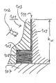
- FIG. 2a and 2b is a schematic cross-sectional illustration thermally controllable arrangement 101 shown.
- a heat source 102 thermally loaded part or heat absorbing element 103 and a heat sink (heat dissipation element) 105 on one heat-insulating base 107 in a storage room 108 a liquid Thermal contact medium 109 with a high coefficient of thermal expansion and high thermal conductivity is provided.
- a storage room 108 Above the Storage room 108 is located between the heat absorbing element 103 and the heat dissipation element 105 a gap 111.
- 3a and 3b are schematic cross-sectional representations of a thermal controllable clutch arrangement 201 with a drive shaft 203, a first clutch disc 205, a second clutch disc 207 and an output shaft 209. Both clutch discs bear on each other facing end faces a friction lining 205a or 207a, and the drive side exposed to thermal energy from the drive source Clutch disc 205 also has a control layer 205b, the Thickness changes depending on the temperature.
- the thickness dK is in the cold state of the (not shown) Drive source less so that between the two clutch discs 205, 207 there is a distance 211, while (as FIG. 3b shows) the thickness when warm on the drive side due to the increase in volume an expansion medium embedded in cavities of the control layer 205b 205c has increased to the value dW so far that the discs 205, 207 are in frictional engagement with each other and the rotation of the drive shaft 203 is transmitted to the output shaft 209.
- FIGS. 3a and 3b An arrangement similar to the type outlined in FIGS. 3a and 3b is also with Interlocking elements can be used instead of the friction linings and can be used as self-regulating thermal coupling for an engine cooling air blower or similar be used.
Landscapes
- Engineering & Computer Science (AREA)
- Chemical & Material Sciences (AREA)
- Combustion & Propulsion (AREA)
- Mechanical Engineering (AREA)
- General Engineering & Computer Science (AREA)
- Thermally Actuated Switches (AREA)
- Control Of Temperature (AREA)
- Cooling Or The Like Of Electrical Apparatus (AREA)
- Thermistors And Varistors (AREA)
- Cooling Or The Like Of Semiconductors Or Solid State Devices (AREA)
- Semiconductor Lasers (AREA)
Claims (11)
- Dispositif à commande thermique (1 ; 101 ; 201) pour l'utilisation sur une source de chaleur (102) pouvant être commandée, comprenant :dans lequel l'élément récepteur de chaleur (9 ; 103 ; 205) et l'élément de commutation (13 ; 109 ; 205b) forment un matériau composite non détachable.un élément récepteur de chaleur thermoconducteur (9 ; 103 ; 205), qui se compose d'un premier matériau avec un premier coefficient de dilatation thermique et qui est en contact thermique avec la source de chaleur ; etun élément de commutation (13 ; 109; 205b) qui est en contact thermique avec l'élément récepteur de chaleur et qui se compose d'un second matériau avec un second coefficient de dilatation thermique plus élevé en comparaison à celui du premier matériau, lequel interrompt ou établit une liaison mécanique ou une transmission de forces et/ou un contact thermique avec un élément de dissipation thermique, en dépendance de l'état de commande de la source de chaleur, via l'effet de sa dilatation thermique ;
- Dispositif à commande thermique pour l'utilisation sur une source de chaleur pouvant être commandée, comprenant :dans lequel l'élément récepteur de chaleur et l'élément de commutation forment un matériau composite non détachable.un élément récepteur de chaleur thermoconducteur, qui se compose d'un premier matériau avec une première température de transition de phase et qui est en contact thermique avec la source de chaleur ; etun élément de commutation qui est en contact thermique avec l'élément récepteur de chaleur et qui se compose d'un second matériau avec une seconde température de transition de phase plus basse en comparaison à celle du premier matériau, lequel interrompt ou établit une liaison mécanique ou une transmission des forces et/ou un contact thermique et/ou électrique avec un élément de dissipation thermique, en dépendance de l'état de commande de la source de chaleur via l'effet d'une modification de l'état de phase,
- Dispositif à commande thermique selon la revendication 2, caractérisé en ce que :l'élément de commutation se compose d'un matériau avec une caractéristique d'hystérésis de la transition de phase ; et/oula transition de phase de l'élément de commutation est une liquéfaction ou un amollissement depuis un état solide.
- Dispositif à commande thermique selon l'une des revendications précédentes, caractérisé en ce que :l'élément de commutation (13 ; 109 ; 205b) est réalisé de manière à présenter une modification de l'état de phase ou une dilatation thermique réversible, essentiellement avec conservation de la forme ; et/oul'élément de commutation (13 ; 109) est noyé au moins partiellement dans une cavité (11 ; 108) de l'élément récepteur de chaleur (9) ou d'un boítier qui l'entoure (103 ; 105 ; 107) ; oul'élément de commutation (205b) comprend une pluralité d'entités qui sont noyées en particulier dans les cavités de l'élément récepteur de chaleur.
- Dispositif à commande thermique selon l'une des revendications précédentes, caractérisé en ce que :une zone d'espace libre (15 ; 211) ou une matière isolante (113) est directement ou indirectement adjacente à au moins un tronçon de l'élément de commutation (13 ; 109 ; 205b) ; et/oul'élément de commutation (13) comporte un matériau métallique ; et/oul'élément récepteur de chaleur (9) comporte un matériau céramique ou métallique.
- Dispositif à commande thermique selon l'une des revendications précédentes, caractérisé par un élément de dissipation thermique (17 à 21 ; 105), lequel est agencé par rapport à l'élément de commutation (13 ; 109) de manière à être isolé thermiquement de l'élément récepteur de chaleur, ou à venir en contact thermique avec celui-ci, via l'effet de la dilatation thermique ou de la modification de l'état de phase de l'élément de commutation, en dépendance de l'état de commande de la source de chaleur (102).
- Dispositif à commande thermique selon la revendication 6, caractérisé en ce que :l'élément récepteur de chaleur est réalisé comme tronçon de la paroi intérieure (9) du compartiment de combustion ou d'un compartiment de gaz d'échappement, ou comme tronçon d'un composant d'une installation ou d'une machine de combustion (1), en voisinage direct avec le compartiment de combustion ou de gaz d'échappement, et l'élément de dissipation thermique est réalisé comme tronçon de la paroi (17) ou du composant, en voisinage non direct avec le compartiment de combustion ou de gaz d'échappement ; etdans un premier état de fonctionnement de l'installation ou de la machine de combustion (1) ou de l'installation industrielle, il existe une distance (15) entre l'élément de commutation (13) et l'élément de dissipation thermique (17 à 21), qui est fermée dans un second état de fonctionnement en raison de la dilatation thermique ou de la modification de l'état de phase de l'élément de commutation.
- Dispositif à commande thermique selon la revendication 6, caractérisé en ce que :l'élément récepteur de chaleur est réalisé comme tronçon de la paroi intérieure d'un compartiment de traitement ou d'un compartiment annexe de traitement, ou comme tronçon d'un composant d'une installation industrielle en voisinage direct avec le compartiment de traitement ou le compartiment annexe de traitement ; etl'élément de dissipation thermique est réalisé comme tronçon de la paroi ou du composant, en voisinage non direct avec le compartiment de traitement ou le compartiment annexe de traitement.
- Dispositif à commande thermique selon l'une des revendications précédentes, caractérisé par :dans lequel le premier organe de coopération de forme ou l'organe enveloppe est formé de préférence par l'élément récepteur de chaleur.un premier et un second organe de coopération de forces ou de formes (205 ; 207), lesquels sont réalisés de manière à être amenés depuis un état sans engagement jusque dans un état d'engagement, en dépendance de l'état de commande de la source de chaleur, via l'effet de la dilatation thermique ou de la modification de l'état de phase de l'élément de commutation ; et/ouun organe enveloppe qui est réalisé et agencé par rapport à l'élément de commutation de sorte que, en dépendance de l'état de commande de la source de chaleur, via l'effet de la dilatation thermique ou de la modification de l'état de phase de l'élément de commutation, la surface de la section transversale d'un canal ou d'une ouverture défini(e) par l'organe enveloppe et par l'élément de commutation, ou le volume d'une zone d'espace définie par l'organe enveloppe et par l'élément de commutation, se modifie ;
- Dispositif à commande thermique selon l'une des revendications 2 à 5, caractérisé par un premier et un second tronçon de circuit de commutation électrique, lesquels sont réalisés de manière à être amenés jusque dans l'état d'un circuit électrique fermé depuis un état interrompu électriquement, en dépendance de l'état de commande de la source de chaleur, via l'effet de la modification de l'état de phase de l'élément de commutation, dans lesquels on préfère que le premier tronçon de circuit de commutation inclut l'élément récepteur de chaleur et que celui-ci soit réalisé comme électriquement conducteur.
- Dispositif à commande thermique selon l'une des revendications précédentes, caractérisé en ce que :divers matériaux sont agencés dans différents secteurs ; et/ouun état graduel est créé par l'utilisation des divers matériaux.
Applications Claiming Priority (2)
| Application Number | Priority Date | Filing Date | Title |
|---|---|---|---|
| DE19802117 | 1998-01-21 | ||
| DE19802117A DE19802117C1 (de) | 1998-01-21 | 1998-01-21 | Thermisch steuerbare Anordnung |
Publications (3)
| Publication Number | Publication Date |
|---|---|
| EP0932093A2 EP0932093A2 (fr) | 1999-07-28 |
| EP0932093A3 EP0932093A3 (fr) | 2000-02-02 |
| EP0932093B1 true EP0932093B1 (fr) | 2004-06-16 |
Family
ID=7855222
Family Applications (1)
| Application Number | Title | Priority Date | Filing Date |
|---|---|---|---|
| EP99100950A Expired - Lifetime EP0932093B1 (fr) | 1998-01-21 | 1999-01-20 | Dispositif à commande thermique |
Country Status (3)
| Country | Link |
|---|---|
| EP (1) | EP0932093B1 (fr) |
| AT (1) | ATE269557T1 (fr) |
| DE (2) | DE19802117C1 (fr) |
Families Citing this family (2)
| Publication number | Priority date | Publication date | Assignee | Title |
|---|---|---|---|---|
| DE19905980C2 (de) * | 1999-02-12 | 2001-02-08 | Fraunhofer Ges Forschung | Kühlvorrichtung und Kühlverfahren |
| CN117158789B (zh) * | 2023-09-20 | 2025-08-01 | 常州心闺蜜生物科技有限公司 | 饮品专用自加热保温装置及其使用方法 |
Family Cites Families (6)
| Publication number | Priority date | Publication date | Assignee | Title |
|---|---|---|---|---|
| US3225820A (en) * | 1962-11-01 | 1965-12-28 | Gen Precision Inc | Device for controlling temperature by heat conduction |
| US3957107A (en) * | 1975-02-27 | 1976-05-18 | The United States Of America As Represented By The Secretary Of The Air Force | Thermal switch |
| DE3017252C2 (de) * | 1980-05-06 | 1982-06-16 | Messerschmitt-Bölkow-Blohm GmbH, 8000 München | Vorrichtung zur Konstanthaltung der Innentemperatur von Körpern |
| WO1983002363A1 (fr) * | 1981-12-29 | 1983-07-07 | Hassan, Javathu, K. | Organe de refroidissement pour un dispositif de puce a circuit integre |
| DE3503151A1 (de) * | 1985-01-31 | 1986-08-07 | Bernhard 4300 Essen Brüne | Absperrvorrichtung fuer automobilheizungssysteme |
| US5694515A (en) * | 1995-01-09 | 1997-12-02 | The University Of Florida | Contact resistance-regulated storage heater for fluids |
-
1998
- 1998-01-21 DE DE19802117A patent/DE19802117C1/de not_active Expired - Fee Related
-
1999
- 1999-01-20 DE DE59909708T patent/DE59909708D1/de not_active Expired - Fee Related
- 1999-01-20 EP EP99100950A patent/EP0932093B1/fr not_active Expired - Lifetime
- 1999-01-20 AT AT99100950T patent/ATE269557T1/de not_active IP Right Cessation
Also Published As
| Publication number | Publication date |
|---|---|
| EP0932093A2 (fr) | 1999-07-28 |
| DE59909708D1 (de) | 2004-07-22 |
| EP0932093A3 (fr) | 2000-02-02 |
| ATE269557T1 (de) | 2004-07-15 |
| DE19802117C1 (de) | 1999-06-02 |
Similar Documents
| Publication | Publication Date | Title |
|---|---|---|
| DE2804557C3 (de) | Flüssigkeitsreibungskupplung, insbesondere für ein Kühlgebläse einer Brennkraftmaschine | |
| EP2630381B1 (fr) | Agencement présentant des dispositifs à refroidissement et/ou chauffage intégré, et procédé pour le chauffage ou le refroidissement intégré | |
| DE10126967B4 (de) | Öffnungs-/Schließventil | |
| DE60036097T2 (de) | Kühlrippe | |
| DE69412833T2 (de) | Zündkerze mit automatischer einstellung des spaltes | |
| DE102015000805B3 (de) | Regelbare Kühlmittelpumpe | |
| DE2212367B2 (de) | Flüssigkeitsreibungskupplung, insbesondere für den Lüfterantrieb von Brennkraftmaschinen | |
| DE112007003802B3 (de) | Kupplungsanordnung mit einem Wärmeübertragungsmedium zum Kühlen einer Antriebsplatte | |
| DE102016120610A1 (de) | Vorrichtung, die Scherkräfte zur Energieübertragung einsetzt, mit strömungsverändernden Strukturen, die ausgestaltet sind, um die Wärmeabgabe von einem Arbeitsfluid zu erhöhen, sowie ein zugehöriges Verfahren | |
| DE102014110329A1 (de) | Thermischer Aktuator mit einem Fluid mit hoher Temperaturstabilität | |
| DE2321767A1 (de) | Betaetigungsorgan zur umwandlung elektrischer energie in lineare mechanische bewegung | |
| EP2908010B1 (fr) | Tige de piston pour compresseurs à pistons et compresseur à pistons | |
| DE2635896C3 (de) | Selbsttätig schaltbarer Ventilator, insbesonders für Kühlsysteme von Verbrennungsmotoren | |
| DE102008041403A1 (de) | Schalteinheit mit mindestens einem elektroaktiven dielektrischen Verformungskörper | |
| DE19802117C1 (de) | Thermisch steuerbare Anordnung | |
| DE102006012719A1 (de) | Stellglied | |
| DE102013205032A1 (de) | Gegenfläche einer Reibpaarung | |
| DE102010019670B4 (de) | Betätigungseinheit mit einem Aktor | |
| DE102009000487A1 (de) | Laserzündkerze | |
| EP1304494B1 (fr) | Embrayage multidisques pour motocyclette | |
| EP4314593B1 (fr) | Amortisseur rotatif à courants de foucault adaptatif en température | |
| DE10112397A1 (de) | Dichtring | |
| DE102012209765A1 (de) | Steuerung von Wärme in einem System mithilfe intelligenter Materialien | |
| EP1274940B1 (fr) | Pompe a gaz de mesure | |
| DE102006037747B4 (de) | Anordnung zur Kühlung eines elektrischen Bauelements |
Legal Events
| Date | Code | Title | Description |
|---|---|---|---|
| PUAI | Public reference made under article 153(3) epc to a published international application that has entered the european phase |
Free format text: ORIGINAL CODE: 0009012 |
|
| AK | Designated contracting states |
Kind code of ref document: A2 Designated state(s): AT BE CH DE DK ES FI FR GB GR IE IT LI LU NL PT SE |
|
| AX | Request for extension of the european patent |
Free format text: AL;LT;LV;MK;RO;SI |
|
| PUAL | Search report despatched |
Free format text: ORIGINAL CODE: 0009013 |
|
| AK | Designated contracting states |
Kind code of ref document: A3 Designated state(s): AT BE CH CY DE DK ES FI FR GB GR IE IT LI LU MC NL PT SE |
|
| AX | Request for extension of the european patent |
Free format text: AL;LT;LV;MK;RO;SI |
|
| RIC1 | Information provided on ipc code assigned before grant |
Free format text: 7G 05D 23/02 A, 7F 03G 7/06 B |
|
| AKX | Designation fees paid | ||
| 17P | Request for examination filed |
Effective date: 20000728 |
|
| RBV | Designated contracting states (corrected) |
Designated state(s): AT BE CH CY DE DK ES FI FR GB GR IE IT LI LU MC NL |
|
| RBV | Designated contracting states (corrected) |
Designated state(s): AT BE CH DE DK ES FI FR GB GR IE IT LI LU NL PT SE |
|
| 17Q | First examination report despatched |
Effective date: 20020924 |
|
| GRAP | Despatch of communication of intention to grant a patent |
Free format text: ORIGINAL CODE: EPIDOSNIGR1 |
|
| GRAS | Grant fee paid |
Free format text: ORIGINAL CODE: EPIDOSNIGR3 |
|
| GRAA | (expected) grant |
Free format text: ORIGINAL CODE: 0009210 |
|
| AK | Designated contracting states |
Kind code of ref document: B1 Designated state(s): AT BE CH DE DK ES FI FR GB GR IE IT LI LU NL PT SE |
|
| PG25 | Lapsed in a contracting state [announced via postgrant information from national office to epo] |
Ref country code: NL Free format text: LAPSE BECAUSE OF FAILURE TO SUBMIT A TRANSLATION OF THE DESCRIPTION OR TO PAY THE FEE WITHIN THE PRESCRIBED TIME-LIMIT Effective date: 20040616 Ref country code: IE Free format text: LAPSE BECAUSE OF FAILURE TO SUBMIT A TRANSLATION OF THE DESCRIPTION OR TO PAY THE FEE WITHIN THE PRESCRIBED TIME-LIMIT Effective date: 20040616 Ref country code: FI Free format text: LAPSE BECAUSE OF FAILURE TO SUBMIT A TRANSLATION OF THE DESCRIPTION OR TO PAY THE FEE WITHIN THE PRESCRIBED TIME-LIMIT Effective date: 20040616 |
|
| REG | Reference to a national code |
Ref country code: GB Ref legal event code: FG4D Free format text: NOT ENGLISH |
|
| REG | Reference to a national code |
Ref country code: CH Ref legal event code: EP |
|
| REF | Corresponds to: |
Ref document number: 59909708 Country of ref document: DE Date of ref document: 20040722 Kind code of ref document: P |
|
| REG | Reference to a national code |
Ref country code: IE Ref legal event code: FG4D Free format text: GERMAN |
|
| GBT | Gb: translation of ep patent filed (gb section 77(6)(a)/1977) |
Effective date: 20040803 |
|
| PG25 | Lapsed in a contracting state [announced via postgrant information from national office to epo] |
Ref country code: SE Free format text: LAPSE BECAUSE OF FAILURE TO SUBMIT A TRANSLATION OF THE DESCRIPTION OR TO PAY THE FEE WITHIN THE PRESCRIBED TIME-LIMIT Effective date: 20040916 Ref country code: GR Free format text: LAPSE BECAUSE OF FAILURE TO SUBMIT A TRANSLATION OF THE DESCRIPTION OR TO PAY THE FEE WITHIN THE PRESCRIBED TIME-LIMIT Effective date: 20040916 Ref country code: DK Free format text: LAPSE BECAUSE OF FAILURE TO SUBMIT A TRANSLATION OF THE DESCRIPTION OR TO PAY THE FEE WITHIN THE PRESCRIBED TIME-LIMIT Effective date: 20040916 |
|
| PG25 | Lapsed in a contracting state [announced via postgrant information from national office to epo] |
Ref country code: ES Free format text: LAPSE BECAUSE OF FAILURE TO SUBMIT A TRANSLATION OF THE DESCRIPTION OR TO PAY THE FEE WITHIN THE PRESCRIBED TIME-LIMIT Effective date: 20040927 |
|
| NLV1 | Nl: lapsed or annulled due to failure to fulfill the requirements of art. 29p and 29m of the patents act | ||
| REG | Reference to a national code |
Ref country code: IE Ref legal event code: FD4D |
|
| ET | Fr: translation filed | ||
| PG25 | Lapsed in a contracting state [announced via postgrant information from national office to epo] |
Ref country code: LU Free format text: LAPSE BECAUSE OF NON-PAYMENT OF DUE FEES Effective date: 20050120 |
|
| PG25 | Lapsed in a contracting state [announced via postgrant information from national office to epo] |
Ref country code: LI Free format text: LAPSE BECAUSE OF NON-PAYMENT OF DUE FEES Effective date: 20050131 Ref country code: CH Free format text: LAPSE BECAUSE OF NON-PAYMENT OF DUE FEES Effective date: 20050131 Ref country code: BE Free format text: LAPSE BECAUSE OF NON-PAYMENT OF DUE FEES Effective date: 20050131 Ref country code: AT Free format text: LAPSE BECAUSE OF NON-PAYMENT OF DUE FEES Effective date: 20050131 |
|
| PLBE | No opposition filed within time limit |
Free format text: ORIGINAL CODE: 0009261 |
|
| STAA | Information on the status of an ep patent application or granted ep patent |
Free format text: STATUS: NO OPPOSITION FILED WITHIN TIME LIMIT |
|
| 26N | No opposition filed |
Effective date: 20050317 |
|
| BERE | Be: lapsed |
Owner name: FORSCHUNGSINSTITUT FUR NICHTEISEN-METALLE FREIBERG Effective date: 20050131 |
|
| PG25 | Lapsed in a contracting state [announced via postgrant information from national office to epo] |
Ref country code: DE Free format text: LAPSE BECAUSE OF NON-PAYMENT OF DUE FEES Effective date: 20050802 |
|
| REG | Reference to a national code |
Ref country code: CH Ref legal event code: PL |
|
| PGFP | Annual fee paid to national office [announced via postgrant information from national office to epo] |
Ref country code: GB Payment date: 20070119 Year of fee payment: 9 |
|
| BERE | Be: lapsed |
Owner name: FORSCHUNGSINSTITUT FUR NICHTEISEN-METALLE FREIBERG Effective date: 20050131 |
|
| PG25 | Lapsed in a contracting state [announced via postgrant information from national office to epo] |
Ref country code: PT Free format text: LAPSE BECAUSE OF NON-PAYMENT OF DUE FEES Effective date: 20041116 |
|
| PGFP | Annual fee paid to national office [announced via postgrant information from national office to epo] |
Ref country code: IT Payment date: 20070614 Year of fee payment: 9 |
|
| PGFP | Annual fee paid to national office [announced via postgrant information from national office to epo] |
Ref country code: FR Payment date: 20070111 Year of fee payment: 9 |
|
| GBPC | Gb: european patent ceased through non-payment of renewal fee |
Effective date: 20080120 |
|
| REG | Reference to a national code |
Ref country code: FR Ref legal event code: ST Effective date: 20081029 |
|
| PG25 | Lapsed in a contracting state [announced via postgrant information from national office to epo] |
Ref country code: GB Free format text: LAPSE BECAUSE OF NON-PAYMENT OF DUE FEES Effective date: 20080120 |
|
| PG25 | Lapsed in a contracting state [announced via postgrant information from national office to epo] |
Ref country code: FR Free format text: LAPSE BECAUSE OF NON-PAYMENT OF DUE FEES Effective date: 20080131 |
|
| PG25 | Lapsed in a contracting state [announced via postgrant information from national office to epo] |
Ref country code: IT Free format text: LAPSE BECAUSE OF NON-PAYMENT OF DUE FEES Effective date: 20080120 |