EP0932251B1 - Funksender und Funkempfänger - Google Patents
Funksender und Funkempfänger Download PDFInfo
- Publication number
- EP0932251B1 EP0932251B1 EP98101136A EP98101136A EP0932251B1 EP 0932251 B1 EP0932251 B1 EP 0932251B1 EP 98101136 A EP98101136 A EP 98101136A EP 98101136 A EP98101136 A EP 98101136A EP 0932251 B1 EP0932251 B1 EP 0932251B1
- Authority
- EP
- European Patent Office
- Prior art keywords
- frequency
- signal
- radio
- local oscillator
- signals
- Prior art date
- Legal status (The legal status is an assumption and is not a legal conclusion. Google has not performed a legal analysis and makes no representation as to the accuracy of the status listed.)
- Expired - Lifetime
Links
- 238000001228 spectrum Methods 0.000 description 10
- 239000013598 vector Substances 0.000 description 8
- 238000010586 diagram Methods 0.000 description 4
- 230000005540 biological transmission Effects 0.000 description 2
- 230000003595 spectral effect Effects 0.000 description 2
- 102100031456 Centriolin Human genes 0.000 description 1
- 101000941711 Homo sapiens Centriolin Proteins 0.000 description 1
- 238000006243 chemical reaction Methods 0.000 description 1
- 230000000694 effects Effects 0.000 description 1
- 230000002441 reversible effect Effects 0.000 description 1
Images


Classifications
-
- H—ELECTRICITY
- H03—ELECTRONIC CIRCUITRY
- H03D—DEMODULATION OR TRANSFERENCE OF MODULATION FROM ONE CARRIER TO ANOTHER
- H03D7/00—Transference of modulation from one carrier to another, e.g. frequency-changing
- H03D7/16—Multiple-frequency-changing
- H03D7/165—Multiple-frequency-changing at least two frequency changers being located in different paths, e.g. in two paths with carriers in quadrature
-
- H—ELECTRICITY
- H03—ELECTRONIC CIRCUITRY
- H03D—DEMODULATION OR TRANSFERENCE OF MODULATION FROM ONE CARRIER TO ANOTHER
- H03D3/00—Demodulation of angle-, frequency- or phase- modulated oscillations
- H03D3/007—Demodulation of angle-, frequency- or phase- modulated oscillations by converting the oscillations into two quadrature related signals
Definitions
- the invention relates to a radio receiver and to a corresponding radio transmitter according to the preambles of the independent claims.
- the frequency of the local oscillator can be selected either above or below the frequencies of the relevant frequency bands.
- the frequency of the oscillator should be variable over a range corresponding to the range of the band, because the difference in frequency between the radio signals and the local oscillator should be equal to the frequency of the intermediate signal, which has a very low bandwidth around a fixed frequency.
- the frequency bands cover a wide frequency range. This is the case for e.g. multiband mobile telephones.
- Such telephones could for instance be adapted to receive and/or transmit signals in the GSM900 band (900 MHz) and the GSM1800 band (1800 MHz).
- the oscillator should be variable over a range of at least 900 MHz, which would be very difficult to implement in practice. Therefore, it will normally be necessary to use a separate local oscillator for each band.
- the frequency of the local oscillator is selected to be between the relevant frequency bands, i.e. above the frequencies of the lower band (e.g. 900 MHz) and below the frequencies of the upper band (1800 MHz), the range over which a single oscillator should be variable (i.e. the bandwidth of the oscillator) is reduced considerably. Therefore, it is possible to implement such an oscillator in practice.
- EP 0 653 851 A2 discloses a radio device for at least a first and second frequency band, converting radio signals to an inter-frequency signal using a mixed frequency.
- a common mixer oscillator is used both for transmitter and receiver.
- a first object of the invention is to improve a radio receiver adapted to receive radio signals in at least two frequency bands, said radio signals being modulated by information signals using a phase modulation or a frequency modulation, the radio receiver comprising i) means for down-converting a received radio signal to an intermediate frequency signal by means of a local oscillator, the frequency of which is so selected that the frequencies of at least one of said frequency bands are above it and the frequencies of at least one of said frequency bands are below it; and ii) demodulating means for recovering the information signals from the intermediate-frequency signal.
- a second object of the invention is to improve a corresponding radio transmitter. Both these objects can be achieved as set out in the independent patent claims.
- the demodulating means is a quadrature demodulator adapted to recover the information signals in the form of an In-phase signal (I signal) and a Quadrature-phase signal (Q signal), and when the modulation of the received radio signals is a phase modulation or a frequency modulation, this compensation may be implemented in one embodiment stated in claim 1, in that the receiver moreover comprises means for assigning one sign (+ or -) to the Q signal when the frequency of the received radio signal is below the frequency of the local oscillator, and the opposite sign when the frequency of the received radio signal is above the frequency of the local oscillator. It can be shown that in the quadrature demodulator the change of side bands means a change of the sign of the Q signal and, therefore, the change may be compensated by changing the sign back.
- the compensation of the change of sidebands may be implemented in that the receiver moreover comprises means for keeping the I signal and the Q signal unchanged when the frequency of the received radio signal is above the frequency of the local oscillator, and for exchanging the I signal and the Q signal when the frequency of the received radio signal is below the frequency of the local oscillator.
- the modulating means is a quadrature modulator adapted to modulate the intermediate frequency signal by information signals in the form of an I signal and a Q signal
- the modulation of the received radio signals is a phase modulation or a frequency modulation
- this compensation may be implemented in one embodiment stated in claim 7, in that the transmitter moreover comprises means for assigning one sign (+ or -) to the Q signal when the frequency of the radio signal is below the frequency of the local oscillator, and the opposite sign when the frequency of the radio signal is above the frequency of the local oscillator.
- a change of the sign of the Q signal corresponds to a change of side bands in the intermediate frequency signal and, therefore, such a change can compensate the sideband change that occurs when the intermediate frequency signal is converted to the radio signal.
- the compensation of the change of sidebands may be implemented in that the transmitter moreover comprises means for keeping the I signal and the Q signal unchanged when the frequency of the radio signal is above the frequency of the local oscillator, and for exchanging the I signal and the Q signal when the frequency of the radio signal is below the frequency of the local oscillator.
- the receiver or the transmitter is adapted to receive or transmit radio signals in only two frequency bands and the frequency of the local oscillator is selected in a range substantially halfway between the two frequency bands, the range over which the single oscillator should be variable is reduced even further to a range of substantially the same size as for each band, because approximately the same oscillator frequencies may be used for both bands. If, for instance, the two bands are the earlier mentioned GSM900 and GSM1800 bands the intermediate frequency could be selected to approximately 450 MHz, causing the frequency of the local oscillator to be in a range around 1350 MHz for both bands.
- FIG 1 shows a receiver 1 for radio signals.
- the incoming radio signals are received at an antenna 2 and taken to a radio frequency tuner and amplifier 3.
- the amplified radio frequency signals are then down-converted to a predetermined intermediate frequency f IF in a frequency converter comprised of a mixer 4 and a local oscillator 5.
- Figure 2 shows the spectrum of the various signals vs. frequency.
- f LO is shown as an arrow at a single frequency, whereas the RF and IF signals are shown as spectrums with a certain spectral distribution. (The specific distribution shown is not important, it may vary depending on the modulation scheme used).
- An L (for low) and H (for high) are used to indicate the position of each part of the RF spectral distribution.
- the RF spectrum is down-converted to the IF spectrum using the LO signal.
- the spectrum of the RF signal remains unaltered, except for the shift to a lower frequency (f IF ).
- f LO is below f RF
- the spectrum of the RF signal is switched, so that the H portion is moved to the low side, and the L portion is moved to the high side.
- the spectrum of the RF signal is replaced by the mirror of the same spectrum at IF (spectrum mirroring or sideband reversal).
- the intermediate frequency signal is fed from an IF amplifier and filter 6 to a demodulator 7.
- a demodulator 7 Very often this will be a quadrature demodulator, and in that case the outputs from the demodulator will be in the form of the two quadrature signals labelled I(t) and Q(t). These signals are then processed in decoding circuitry in the apparatus.
- this part of the apparatus is not relevant for the invention, it is not shown in the Figure.
- the function of the quadrature demodulator will be described later.
- a receiver according to the invention is adapted to receive radio signals in at least two different frequency bands.
- multiband mobile telephones could be adapted to receive and/or transmit signals in the GSM900 band (900 MHz) and the GSM1800 band (1800 MHz). If the frequency of the local oscillator is selected above f RF for the lower band and below f RF for the higher band, as is shown in Figure 3, the frequencies of the local oscillator could be selected from the same range for both bands. However, as mentioned above, this will have the drawback that the sideband reversal will take place for the lower band. This means that when the receiver switches from one band to the other, a switch of sidebands will take place in the intermediate frequency signal, and such a switch is normally not allowable.
- the circuit may be modified as shown in Figure 4.
- an amplifier is provided for each band, i.e. an amplifier 8 for one band (e.g. GSM900) and an amplifier 9 for the other band (GSM1800).
- the input from the antenna 2 is passed through a diplexer 10, which is a combination of bandpass filters separating the two bands.
- a switch 11 selects which of the two amplified radio frequency signals is sent to the mixer 4.
- the circuit is similar to that of Figure 1.
- the function of the quadrature modulator and demodulator will be described in the following.
- the demodulator is used in the receiver and the modulator correspondingly in a transmitter.
- the function of the modulator is to move information from baseband up to a carrier which is the intermediate frequency (f IF ) in this case.
- the quadrature modulator is a special modulator, characterized by its ability to be used at both amplitude modulation (AM), phase modulation (PM) and frequency modulation (FM) and also at the digital equivalents PSK and FSK.
- the quadrature modulator is able to suppress the carrier itself and unwanted mixing products (spurious signals), a functionality which is often hard to achieve using other types of modulators.
- (A.2) is the general expression for a modulated signal.
- A(t) is the amplitude of the modulated signal s(t)
- ⁇ (t) is the phase of s(t).
- the signal vector s(t) with length A(t) and angle ⁇ (t) is shown in Figure 6.
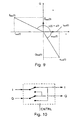
- the function of the quadrature demodulator is to move information from the IF frequency in this case down to baseband. This is described through the diagram in Figure 7.
- the signal (t) may be calculated as
- the high frequency terms are removed by means of the low-pass filter, and the result is the baseband signal I(t).
- Q(t) may be obtained similarly.
- phase ⁇ (t) changes sign when a switch is made between GSM900 and GSM1800.
- the vector signal diagram shown in Figure 8 may be constructed from equations (A.13) and (A.14).
- Î 900 (t) and Q and 900 (t) denotes the I- and Q-signals after the swapping.
- the swapping of the I and Q signals may be implemented with an analog switch circuitry, as shown in Figure 10, where the CNTRL input places the switch in the lower position for GSM900 (swap) and in the upper position for GSM1800 (no swap).
- bits may be inverted after the differential decoder. This may be done in hardware or software.
- a conFiguration similar to that in Figure 10 may be used to invert the bitstream internally in the baseband unit.
- the I and Q signals from the coding circuitry are fed to the modulator 22, which was shown in Figure 5.
- the modulated intermediate frequency signal is amplified in the amplifier 23 and then mixed with the signal from the local oscillator 25 in the mixer 24.
- the output from the mixer 24 contains signals in both radio frequency bands and in the diplexer they are divided between the two radio frequency amplifiers 27 and 28.
- a switch 29 selects which of the two signals is fed to the antenna 30.
- a sideband reversal occurs in the radio frequency signals when the transmitter shifts between the two bands. Again, it can be shown in the same way as above that this reversal effect may be compensated by a change of sign of the Q signal or by swapping the I and Q signals before they are fed to the modulator 22.
Landscapes
- Engineering & Computer Science (AREA)
- Power Engineering (AREA)
- Transceivers (AREA)
- Digital Transmission Methods That Use Modulated Carrier Waves (AREA)
Claims (4)
- Funkempfänger (1), der so angepasst ist, dass er Funksignale in mindestens zwei Frequenzbändern empfängt, wobei besagte Funksignale durch Informationssignale mit Hilfe von Phasenmodulation oder Frequenzmodulation moduliert werden und wobei besagter Funkempfänger Folgendes beinhaltet:dadurch gekennzeichnet, dass:ein Mittel (4, 5) zum Abwärtskonvertieren eines empfangenen Funksignals in ein Zwischenfrequenzsignal mittels eines Überlagerungsoszillators (5), dessen Frequenz so ausgewählt wird, dass die Frequenzen von mindestens einem der besagten Frequenzbänder darüber liegen und die Frequenzen von mindestens einem der besagten Frequenzbänder darunter liegen;ein Demodulationsmittel (7) zur Wiedergewinnung der Informationssignale aus dem Zwischenfrequenzsignal;besagtes Demodulationsmittel (7) ein Quadraturdemodulator ist, der so angepasst ist, dass er die Informationssignale in Form eines gleichphasigen Signals (I-Signal) und eines Quadraturphasensignals (Q-Signal) wiedergewinnt, und dass der Funkempfänger (1) zudem Mittel für Folgendes beinhaltet:ein Vorzeichen (+ oder -) dem Q-Signal zuzuweisen, wenn die Frequenz des empfangenen Funksignals unterhalb der Frequenz des Überlagerungsoszillators liegt, und des entgegengesetzten Vorzeichens, wenn die Frequenz des empfangenen Funksignals oberhalb der Frequenz des Überlagerungsoszillators liegt; oderdas I-Signal und das Q-Signal unverändert zu lassen, wenn die Frequenz des empfangenen Funksignals oberhalb der Frequenz des Überlagerungsoszillators liegt, und das I-Signal mit dem Q-Signal zu vertauschen, wenn die Frequenz des empfangenen Funksignals unterhalb der Frequenz des Überlagerungsoszillators liegt.
- Funkempfänger nach Anspruch 1, bei dem: die Frequenz des Überlagerungsoszillators (5) in einem Bereich ausgewählt wird, der im Wesentlichen auf halber Strecke zwischen den beiden Frequenzbändern liegt.
- Funksender (21), der so angepasst ist, dass er Funksignale in mindestens zwei Frequenzbändern sendet, wobei er eine Phasenmodulation oder eine Frequenzmodulation anwendet und wobei besagter Funksender Folgendes beinhaltet:dadurch gekennzeichnet, dass:ein Mittel (22) zum Modulieren eines Zwischenfrequenzsignals mit Hilfe von Informationssignalen;Mittel (24, 25) zum Konvertieren des Zwischenfrequenzsignals in ein Funksignal, und zwar mit Hilfe eines Überlagerungsoszillators (25), dessen Frequenz so ausgewählt wird, dass die Frequenzen von mindestens einem der besagten Frequenzbänder oberhalb seiner Frequenz und die Frequenzen von mindestens einem der besagten Frequenzbänder unterhalb seiner Frequenz liegen; undein Mittel (30) zur Übertragung besagten Funksignals;besagtes Modulationsmittel (22) ein Quadraturmodulator ist, der so angepasst ist, dass er die Zwischenfrequenzsignale in Form eines gleichphasigen Signals (I-Signal) und eines Quadraturphasensignals (Q-Signal) moduliert und dass der Empfänger zudem Mittel für Folgendes beinhaltet:ein Vorzeichen (+ oder -) dem Q-Signal zuzuweisen, wenn die Frequenz des Funksignals unterhalb der Frequenz des Überlagerungsoszillators liegt, und des entgegengesetzten Vorzeichens, wenn die Frequenz des Funksignals oberhalb der Frequenz des Überlagerungsoszillators liegt; oderdas I-Signal und das Q-Signal unverändert zu lassen, wenn die Frequenz des Funksignals oberhalb der Frequenz des Überlagerungsoszillators liegt, und das I-Signal mit dem Q-Signal zu vertauschen, wenn die Frequenz des Funksignals unterhalb der Frequenz des Überlagerungsoszillators liegt.
- Funksender nach Anspruch 3, bei dem: die Frequenz des Überlagerungsoszillators (25) in einem Bereich ausgewählt wird, der im Wesentlichen auf halber Strecke zwischen den beiden Frequenzbändern liegt.
Priority Applications (4)
| Application Number | Priority Date | Filing Date | Title |
|---|---|---|---|
| DE69829835T DE69829835T2 (de) | 1998-01-23 | 1998-01-23 | Funksender und Funkempfänger |
| DK98101136T DK0932251T3 (da) | 1998-01-23 | 1998-01-23 | Radiosender og radiomodtager |
| EP98101136A EP0932251B1 (de) | 1998-01-23 | 1998-01-23 | Funksender und Funkempfänger |
| US09/235,662 US6373883B1 (en) | 1998-01-23 | 1999-01-22 | Radio receiver and a radio transmitter |
Applications Claiming Priority (1)
| Application Number | Priority Date | Filing Date | Title |
|---|---|---|---|
| EP98101136A EP0932251B1 (de) | 1998-01-23 | 1998-01-23 | Funksender und Funkempfänger |
Publications (2)
| Publication Number | Publication Date |
|---|---|
| EP0932251A1 EP0932251A1 (de) | 1999-07-28 |
| EP0932251B1 true EP0932251B1 (de) | 2005-04-20 |
Family
ID=8231298
Family Applications (1)
| Application Number | Title | Priority Date | Filing Date |
|---|---|---|---|
| EP98101136A Expired - Lifetime EP0932251B1 (de) | 1998-01-23 | 1998-01-23 | Funksender und Funkempfänger |
Country Status (4)
| Country | Link |
|---|---|
| US (1) | US6373883B1 (de) |
| EP (1) | EP0932251B1 (de) |
| DE (1) | DE69829835T2 (de) |
| DK (1) | DK0932251T3 (de) |
Families Citing this family (19)
| Publication number | Priority date | Publication date | Assignee | Title |
|---|---|---|---|---|
| JP2001008118A (ja) * | 1999-06-22 | 2001-01-12 | Alps Electric Co Ltd | デジタルテレビジョンチューナ |
| US7127010B1 (en) * | 1999-07-29 | 2006-10-24 | Bose Corporation | Oscillator controlling |
| US6510317B1 (en) * | 1999-11-04 | 2003-01-21 | Xm Satellite Radio, Inc. | Satellite digital audio radio service tuner architecture for reception of satellite and terrestrial signals |
| US6728527B2 (en) * | 2001-07-10 | 2004-04-27 | Asulab S.A. | Double up-conversion modulator |
| US6950478B1 (en) * | 2001-08-02 | 2005-09-27 | Texas Instruments Incorporated | Transmitter and method having a low sampling frequency for digital to analog conversion |
| US20050143031A1 (en) * | 2002-02-06 | 2005-06-30 | Oswald Moonen | Multi-band receiver |
| US7415243B2 (en) | 2003-03-27 | 2008-08-19 | Honda Giken Kogyo Kabushiki Kaisha | System, method and computer program product for receiving data from a satellite radio network |
| US7818380B2 (en) * | 2003-12-15 | 2010-10-19 | Honda Motor Co., Ltd. | Method and system for broadcasting safety messages to a vehicle |
| US8041779B2 (en) * | 2003-12-15 | 2011-10-18 | Honda Motor Co., Ltd. | Method and system for facilitating the exchange of information between a vehicle and a remote location |
| US11152971B2 (en) * | 2004-02-02 | 2021-10-19 | Charles Abraham | Frequency modulated OFDM over various communication media |
| WO2005099379A2 (en) | 2004-04-06 | 2005-10-27 | Honda Motor Co., Ltd. | Method and system for controlling the exchange of vehicle related messages |
| US7518530B2 (en) * | 2004-07-19 | 2009-04-14 | Honda Motor Co., Ltd. | Method and system for broadcasting audio and visual display messages to a vehicle |
| US7391317B2 (en) * | 2004-09-08 | 2008-06-24 | Satius, Inc. | Apparatus and method for transmitting digital data over various communication media |
| US7643788B2 (en) * | 2004-09-22 | 2010-01-05 | Honda Motor Co., Ltd. | Method and system for broadcasting data messages to a vehicle |
| US7562049B2 (en) * | 2005-03-29 | 2009-07-14 | Honda Motor Co., Ltd. | Payment system and method for data broadcasted from a remote location to vehicles |
| US7949330B2 (en) | 2005-08-25 | 2011-05-24 | Honda Motor Co., Ltd. | System and method for providing weather warnings and alerts |
| US7668653B2 (en) | 2007-05-31 | 2010-02-23 | Honda Motor Co., Ltd. | System and method for selectively filtering and providing event program information |
| US8099308B2 (en) | 2007-10-02 | 2012-01-17 | Honda Motor Co., Ltd. | Method and system for vehicle service appointments based on diagnostic trouble codes |
| CN105981303A (zh) | 2014-02-12 | 2016-09-28 | 瑞典爱立信有限公司 | 多频带接收器中的方法和布置 |
Family Cites Families (7)
| Publication number | Priority date | Publication date | Assignee | Title |
|---|---|---|---|---|
| GB9211712D0 (en) * | 1992-06-03 | 1992-07-15 | Fujitsu Microelectronics Ltd | Gm digital receive processing |
| FI109736B (fi) * | 1993-11-01 | 2002-09-30 | Nokia Corp | Vastaanottimen taajuusalueen ja kaistanleveyden vaihto peilitaajuutta vaimentavan sekoittimen avulla |
| DE4338721A1 (de) * | 1993-11-12 | 1995-05-18 | Philips Patentverwaltung | Mehrband-Funkgerät |
| GB9501243D0 (en) * | 1995-01-23 | 1995-03-15 | Rca Thomson Licensing Corp | Local oscillator using digital handswitching |
| FR2745131A1 (fr) * | 1996-02-21 | 1997-08-22 | Philips Electronics Nv | Appareil de radio-telephonie multimode |
| JPH09275358A (ja) * | 1996-04-08 | 1997-10-21 | Matsushita Electric Ind Co Ltd | 複数帯域移動無線装置 |
| US6208875B1 (en) * | 1998-04-08 | 2001-03-27 | Conexant Systems, Inc. | RF architecture for cellular dual-band telephones |
-
1998
- 1998-01-23 DK DK98101136T patent/DK0932251T3/da active
- 1998-01-23 EP EP98101136A patent/EP0932251B1/de not_active Expired - Lifetime
- 1998-01-23 DE DE69829835T patent/DE69829835T2/de not_active Expired - Lifetime
-
1999
- 1999-01-22 US US09/235,662 patent/US6373883B1/en not_active Expired - Fee Related
Also Published As
| Publication number | Publication date |
|---|---|
| DE69829835D1 (de) | 2005-05-25 |
| DK0932251T3 (da) | 2005-05-23 |
| US6373883B1 (en) | 2002-04-16 |
| DE69829835T2 (de) | 2005-11-24 |
| EP0932251A1 (de) | 1999-07-28 |
Similar Documents
| Publication | Publication Date | Title |
|---|---|---|
| EP0932251B1 (de) | Funksender und Funkempfänger | |
| US5495500A (en) | Homodyne radio architecture for direct sequence spread spectrum data reception | |
| US6334051B1 (en) | Direct conversion receiver with wide band analog frequency conversion front end and digital demodulating and selecting back end | |
| JP3647894B2 (ja) | アナログオーバーサンプリングを用いて信号帯域幅を増大する中間周波数fm受信機 | |
| AU755670B2 (en) | Direct conversion receiver | |
| WO1997008842A1 (en) | Near direct conversion receiver and method for equalizing amplitude and phase therein | |
| JP2003509909A (ja) | 角度変調rf信号に対する位相補間受信機 | |
| US7345551B2 (en) | Frequency synthesizer for mixing reference frequencies | |
| US7046979B2 (en) | Receiver for rejecting image signal | |
| EP0875988B1 (de) | Interferenzunterdrückung für HF-Signale | |
| EP1408618A1 (de) | Funksignalempfangsvorrichtung und demodulationsschaltung | |
| US7421040B2 (en) | Modem tuner | |
| KR100656768B1 (ko) | 신규한 저비용/저전력의 아날로그 송수신기 구조 | |
| US6968159B2 (en) | Frequency converter and communication device | |
| JP3993573B2 (ja) | 複数の無線システムに対応可能な無線通信装置 | |
| JP3743046B2 (ja) | 直接変換受信機 | |
| JPH0774790A (ja) | 非線形歪補償送受信回路 | |
| JPH1032519A (ja) | 無線通信機 | |
| JP3252201B2 (ja) | デジタル方式自動車電話機 | |
| JP3153158B2 (ja) | デジタル変調波送受信方式と送受信装置 | |
| WO1999000910A1 (en) | Communication device | |
| JP3756037B2 (ja) | テレビジョンチューナ | |
| JPS63266932A (ja) | 送受信機 | |
| JPH07326932A (ja) | ディジタル無線機の局部発振回路 | |
| JPH0786970A (ja) | ディジタル移動通信用受信機 |
Legal Events
| Date | Code | Title | Description |
|---|---|---|---|
| PUAI | Public reference made under article 153(3) epc to a published international application that has entered the european phase |
Free format text: ORIGINAL CODE: 0009012 |
|
| AK | Designated contracting states |
Kind code of ref document: A1 Designated state(s): DE DK FI GB SE |
|
| 17P | Request for examination filed |
Effective date: 20000128 |
|
| AKX | Designation fees paid |
Free format text: DE DK FI GB SE |
|
| RAP1 | Party data changed (applicant data changed or rights of an application transferred) |
Owner name: SIEMENS AKTIENGESELLSCHAFT |
|
| 17Q | First examination report despatched |
Effective date: 20040803 |
|
| GRAP | Despatch of communication of intention to grant a patent |
Free format text: ORIGINAL CODE: EPIDOSNIGR1 |
|
| GRAS | Grant fee paid |
Free format text: ORIGINAL CODE: EPIDOSNIGR3 |
|
| GRAA | (expected) grant |
Free format text: ORIGINAL CODE: 0009210 |
|
| AK | Designated contracting states |
Kind code of ref document: B1 Designated state(s): DE DK FI GB SE |
|
| REG | Reference to a national code |
Ref country code: GB Ref legal event code: FG4D |
|
| REG | Reference to a national code |
Ref country code: DK Ref legal event code: T3 |
|
| REF | Corresponds to: |
Ref document number: 69829835 Country of ref document: DE Date of ref document: 20050525 Kind code of ref document: P |
|
| REG | Reference to a national code |
Ref country code: SE Ref legal event code: TRGR |
|
| PLBE | No opposition filed within time limit |
Free format text: ORIGINAL CODE: 0009261 |
|
| STAA | Information on the status of an ep patent application or granted ep patent |
Free format text: STATUS: NO OPPOSITION FILED WITHIN TIME LIMIT |
|
| 26N | No opposition filed |
Effective date: 20060123 |
|
| PGFP | Annual fee paid to national office [announced via postgrant information from national office to epo] |
Ref country code: DK Payment date: 20070112 Year of fee payment: 10 |
|
| REG | Reference to a national code |
Ref country code: DK Ref legal event code: EBP |
|
| PGFP | Annual fee paid to national office [announced via postgrant information from national office to epo] |
Ref country code: FI Payment date: 20080710 Year of fee payment: 11 |
|
| PG25 | Lapsed in a contracting state [announced via postgrant information from national office to epo] |
Ref country code: DK Free format text: LAPSE BECAUSE OF NON-PAYMENT OF DUE FEES Effective date: 20080131 |
|
| PGFP | Annual fee paid to national office [announced via postgrant information from national office to epo] |
Ref country code: SE Payment date: 20080729 Year of fee payment: 11 |
|
| EUG | Se: european patent has lapsed | ||
| PG25 | Lapsed in a contracting state [announced via postgrant information from national office to epo] |
Ref country code: FI Free format text: LAPSE BECAUSE OF NON-PAYMENT OF DUE FEES Effective date: 20090123 |
|
| REG | Reference to a national code |
Ref country code: GB Ref legal event code: 732E Free format text: REGISTERED BETWEEN 20100812 AND 20100818 |
|
| REG | Reference to a national code |
Ref country code: GB Ref legal event code: 732E Free format text: REGISTERED BETWEEN 20100826 AND 20100901 |
|
| REG | Reference to a national code |
Ref country code: GB Ref legal event code: 732E Free format text: REGISTERED BETWEEN 20110407 AND 20110413 |
|
| PG25 | Lapsed in a contracting state [announced via postgrant information from national office to epo] |
Ref country code: SE Free format text: LAPSE BECAUSE OF NON-PAYMENT OF DUE FEES Effective date: 20090124 |
|
| REG | Reference to a national code |
Ref country code: DE Ref legal event code: R081 Ref document number: 69829835 Country of ref document: DE Owner name: QUALCOMM INCORPORATED, SAN DIEGO, US Free format text: FORMER OWNER: PALM, INC. (N.D.GES. D. STAATES DELAWARE), SUNNYVALE, CALIF., US Effective date: 20110406 Ref country code: DE Ref legal event code: R081 Ref document number: 69829835 Country of ref document: DE Owner name: QUALCOMM INCORPORATED, US Free format text: FORMER OWNER: PALM, INC. (N.D.GES. D. STAATES DELAWARE), SUNNYVALE, US Effective date: 20110406 |
|
| REG | Reference to a national code |
Ref country code: DE Ref legal event code: R082 Ref document number: 69829835 Country of ref document: DE Representative=s name: SAMSON & PARTNER, PATENTANWAELTE, DE |
|
| REG | Reference to a national code |
Ref country code: DE Ref legal event code: R082 Ref document number: 69829835 Country of ref document: DE Representative=s name: MAUCHER JENKINS, DE Effective date: 20140307 Ref country code: DE Ref legal event code: R082 Ref document number: 69829835 Country of ref document: DE Representative=s name: SAMSON & PARTNER PATENTANWAELTE MBB, DE Effective date: 20140307 Ref country code: DE Ref legal event code: R082 Ref document number: 69829835 Country of ref document: DE Representative=s name: SAMSON & PARTNER, PATENTANWAELTE, DE Effective date: 20140307 Ref country code: DE Ref legal event code: R081 Ref document number: 69829835 Country of ref document: DE Owner name: QUALCOMM INCORPORATED, SAN DIEGO, US Free format text: FORMER OWNER: HEWLETT-PACKARD DEVELOPMENT COMPANY, L.P., HOUSTON, TEX., US Effective date: 20140307 Ref country code: DE Ref legal event code: R081 Ref document number: 69829835 Country of ref document: DE Owner name: QUALCOMM INCORPORATED, US Free format text: FORMER OWNER: HEWLETT-PACKARD DEVELOPMENT CO., L.P., HOUSTON, US Effective date: 20140307 |
|
| REG | Reference to a national code |
Ref country code: GB Ref legal event code: 732E Free format text: REGISTERED BETWEEN 20140508 AND 20140514 |
|
| PGFP | Annual fee paid to national office [announced via postgrant information from national office to epo] |
Ref country code: GB Payment date: 20161228 Year of fee payment: 20 |
|
| PGFP | Annual fee paid to national office [announced via postgrant information from national office to epo] |
Ref country code: DE Payment date: 20170131 Year of fee payment: 20 |
|
| REG | Reference to a national code |
Ref country code: DE Ref legal event code: R082 Ref document number: 69829835 Country of ref document: DE Representative=s name: MAUCHER JENKINS, DE |
|
| REG | Reference to a national code |
Ref country code: DE Ref legal event code: R071 Ref document number: 69829835 Country of ref document: DE |
|
| REG | Reference to a national code |
Ref country code: GB Ref legal event code: PE20 Expiry date: 20180122 |
|
| PG25 | Lapsed in a contracting state [announced via postgrant information from national office to epo] |
Ref country code: GB Free format text: LAPSE BECAUSE OF EXPIRATION OF PROTECTION Effective date: 20180122 |