EP0932310B1 - Schaltung zur Konvergenzkorrektur in einem Fernsehempfänger - Google Patents
Schaltung zur Konvergenzkorrektur in einem Fernsehempfänger Download PDFInfo
- Publication number
- EP0932310B1 EP0932310B1 EP99100129A EP99100129A EP0932310B1 EP 0932310 B1 EP0932310 B1 EP 0932310B1 EP 99100129 A EP99100129 A EP 99100129A EP 99100129 A EP99100129 A EP 99100129A EP 0932310 B1 EP0932310 B1 EP 0932310B1
- Authority
- EP
- European Patent Office
- Prior art keywords
- correction
- convergence
- television receiver
- picture screen
- colour television
- Prior art date
- Legal status (The legal status is an assumption and is not a legal conclusion. Google has not performed a legal analysis and makes no representation as to the accuracy of the status listed.)
- Expired - Lifetime
Links
- 238000012937 correction Methods 0.000 title claims description 72
- 238000000034 method Methods 0.000 claims description 22
- 238000005259 measurement Methods 0.000 claims description 6
- 230000007547 defect Effects 0.000 claims description 2
- 230000003287 optical effect Effects 0.000 claims description 2
- 238000010586 diagram Methods 0.000 description 5
- 238000013461 design Methods 0.000 description 3
- 238000011161 development Methods 0.000 description 3
- 230000018109 developmental process Effects 0.000 description 3
- 230000006870 function Effects 0.000 description 3
- 230000003321 amplification Effects 0.000 description 2
- 238000003702 image correction Methods 0.000 description 2
- 238000003199 nucleic acid amplification method Methods 0.000 description 2
- 238000003860 storage Methods 0.000 description 2
- 238000012360 testing method Methods 0.000 description 2
- 240000000136 Scabiosa atropurpurea Species 0.000 description 1
- 238000006073 displacement reaction Methods 0.000 description 1
- 238000010894 electron beam technology Methods 0.000 description 1
- 238000012804 iterative process Methods 0.000 description 1
- 238000004519 manufacturing process Methods 0.000 description 1
- 230000000750 progressive effect Effects 0.000 description 1
- 239000004065 semiconductor Substances 0.000 description 1
- 238000011144 upstream manufacturing Methods 0.000 description 1
Images

Classifications
-
- H—ELECTRICITY
- H04—ELECTRIC COMMUNICATION TECHNIQUE
- H04N—PICTORIAL COMMUNICATION, e.g. TELEVISION
- H04N9/00—Details of colour television systems
- H04N9/12—Picture reproducers
- H04N9/16—Picture reproducers using cathode ray tubes
- H04N9/28—Arrangements for convergence or focusing
Definitions
- the invention relates to a colour television receiver.
- the invention proceeds from a device for convergence correction in a colour television receiver in accordance with the preamble of Claim 1.
- Such a device serves fundamentally for the correction of parameters in the raster deflection, for example the correction of north/south and east/west distortions, of pin-cushion distortions, of nonlinearities in the deflection, and other geometric distortions in the horizontal or vertical directions.
- a particular field of application is convergence correction in a television projection receiver in which the pictures of three monochromatic picture tubes are projected onto a picture surface.
- the television receiver is understood as any receiver in which pictures are reproduced electronically or using a raster.
- the receiver can be fed from an arbitrary video signal source with a conventional television broadcast signal, or as a pure monitor with an RGB signal, an FBAS signal or, separately, with a luminance signal and a colour carrier.
- the correction of the deflection parameters is undertaken with the aid of correction values which are stored in a convergence circuit.
- the correction values have been determined from a multiplicity of individual receivers from a specific series in such a way that the best correction is achieved on average.
- the correction values stored in the convergence circuit are converted in a digital-to-analogue converter into an analogue control signal and fed to a driver circuit consisting of a preamplifier and an output amplifier.
- This driver circuit outputs a current, corresponding to the correction value, to a correction coil.
- the magnitude of the correction current also depends on the gain of the driver circuit, and can therefore vary from receiver to receiver.
- the colour television receiver according to the invention has the advantage that a single digital data record of correction values in different colour television receivers always causes the same deflection for correcting the pictures independently of the gains of the driver circuits.
- a further advantage of the invention is that the maximum available resolution of the digital correction values can also be utilized in practice.
- the convergence circuit can comprise a digital-to-analogue converter which converts the stored correction values into an analogue control signal for at least one correction device.
- This exemplary embodiment permits a particularly expedient storage of the correction values in a digital storage medium, with the result that conventional memory chips can be used.
- control means can advantageously be constructed such that the analogue control signal output to the driver circuit can be influenced. It is particularly advantageous when the control means comprise electronically adjustable resistors in order to influence the analogue control signal.
- control means can also be constructed such that the digital value fed to the digital-to-analogue converter can be influenced. It is expedient for this to be done by multiplying a digital matching factor by the stored correction value, and feeding the product obtained in this way to the digital-to-analogue converter as input value.
- the matching factor and thus the product of the correction value and the matching factor, are selected such that the correction achieved on the picture screen by means of the correction values is independent, for a specific correction value, of the actual gain of the driver circuit.
- the convergence circuit can be switched over optionally between two operating modes.
- One operating mode is active when a picture is represented on the picture screen, while the other operating mode is activated upon calibration of the convergence circuit.
- reference values stored in a memory can be processed in the convergence circuit.
- One development of the invention can have means for generating a horizontal and/or a vertical structure on the picture screen, for example in the form of a continuous or broken line. This proves to be advantageous in the calibration of a convergence channel.
- Other advantageous developments of the invention are the subject-matter of subclaims.
- a second aspect of the invention relates to a method for setting the convergence in a television receiver.
- the first step is to determine the deflection of a cursor on the picture screen which is actually effected by a convergence channel. These actual data are then used to determine a control signal by means of which the convergence channel is calibrated to prescribed desired values. It is particularly advantageous when the said deflection is determined by optical measurements.
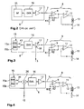
- Fig. 1 shows a top view from the front of the picture screen 1 of a television receiver according to the invention, onto which the pictures of three monochromatic picture tubes 2, 3, 4 are projected.
- the picture tubes 2..4 are arranged in geometrically differing ways. Consequently, image defects which are different for the individual picture tubes occur on the picture screen.
- These picture errors are corrected using supplementary correction coils which are mounted upstream of the actual deflection coils on the coil neck of the picture tubes. The correction is performed for each individual picture tube 2..4 both in the horizontal and in the vertical direction, that is to say a total of six correction coils with the associated driver circuits are present in the television receiver, being driven by a convergence circuit.
- a convergence channel such as is known in the prior art is represented diagrammatically in the block diagram of Figure 2.
- a convergence circuit 6, which is constructed as an integrated circuit, is connected with an output 7 to a driver circuit 8 which comprises a preamplifier 9 and a main amplifier 11.
- the output 12 of the output amplifier 11 is connected to a correction coil 13 which influences the electron beam in the assigned picture tube.
- the correction coil 13 is connected in series to a load resistance 14.
- a convergence circuit 6 with the associated driver circuit 8 and correction coil 13 is denoted below in each case as a convergence channel.
- the further five convergence channels are of identical design.
- the convergence correction is undertaken with the aid of stored digital convergence correction values.
- the convergence correction values are stored in a memory 15, denoted by M, in the convergence circuit 6, and are converted in a digital-to-analogue converter 16 into a corresponding analogue value.
- This analogue value is amplified by means of an amplifier 17, integrated in the convergence circuit 6, with a constant gain f1, and output at the output 7 to the driver circuit 8.
- the driver circuit 8 amplifies the analogue correction value, output by the convergence circuit 6, by means of a constant gain f2, and outputs a corresponding current to the correction coil 13.
- the magnitude of the gain f2 varies from television receiver to television receiver because of component tolerances. The result is that an identical set of correction values leads in different television receivers to different image corrections.
- Fig. 3 shows a block diagram of a convergence channel such as is used in an exemplary embodiment of the invention. This circuit differs from that described above only in the design of the convergence circuit 6.
- the amplifier 17' integrated in the convergence circuit 6 is designed as an amplifier with a variable gain f1, by contrast with the known convergence circuit 6 represented in Fig. 2, in the case of which the gain f1 of the amplifier 17 is constant.
- the control signal S is generated by an external measuring device (not shown). The way in which this is performed will be described further below.
- f0 f1 x f2
- a further difference from the circuit represented in Fig. 2 is that the memory 15 is divided into a first and a second memory area 15a, 15b.
- the convergence values which are used for the convergence correction are stored in the first memory area 15a, while a television picture is represented on the screen 1.
- Specific reference values RW which serve to measure the total gain f0 of the respective convergence channel are stored in the second memory area 15b.
- the memory areas 15a, 15b can be addressed optionally by a switch 41, depending on which operating state of the circuit currently obtains.
- the operating state during which a picture is represented is denoted below as "display mode”.
- the operating state during which the reference value is output is denoted below as "test mode”.
- FIG. 4 An alternative embodiment of the circuit represented in Fig. 3 is shown in Fig. 4.
- an amplifier 17 which again has a constant gain f1 is integrated in the convergence circuit 6.
- a multiplier stage 26 in which the convergence correction values KW read out of the memory 15a, or the reference values RW read out of the memory 15b are multiplied by a matching factor f3.
- the product of these two digital values is input into the input of the digital-to-analogue converter 16 and then processed further in the same way as in the circuit described in Fig. 2.
- the function of the matching factor f3 corresponds to the function of the control signal S in Fig. 3. Therefore, in order to shorten the description, the term "control signal S" is also always to be understood below as the matching factor f3.
- the multiplier stage 26 can also be integrated in the D/A converter 16 in a modified embodiment of the invention.
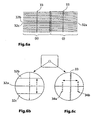
- Fig. 5 will now be used below to describe how the control signal is determined by means of the external measuring device in order to set the total gain f0 of all the convergence channels to a constant value:
- the convergence device 6 is firstly switched into the "test mode" by the external measuring device.
- a horizontal bright line 32 (Fig. 5a) is generated by one of the picture tubes in the case of an uncorrected and dark picture.
- This bright line is denoted below as the gain cursor 32.
- the gain cursor 32 is preferably located in the middle of the picture screen since geometrical distortions are least there in the case of a television receiver with uncorrected convergence.
- the absolute position of the vertical gain cursor 32 on the picture screen 1 is determined without any influencing by correction currents, for example using a high-resolution camera.
- a vertical line 33 is represented in addition to the gain cursor 32.
- the gain cursor 32 is displaced by means of a defined digital reference value, which is read out from the memory area 15b, in the vertical direction, for example upwards on the picture screen 1. This position is determined, in turn, using the high-resolution camera (Fig. 5b). After the gain cursor 32 has returned to the position without being influenced in any way by correction currents (Fig. 5c), it is subsequently deflected in the opposite direction (Fig. 5d). The movements of the gain cursor are caused by corresponding reference values. In the process, the reference values assume values which can correspond to the largest or the smallest convergence correction value, and thus to the largest or smallest deflection of the image by means of the convergence coils.
- the measuring device determines the control signal S from the difference between the position data, supplied by the camera, of the gain cursor as deflected upwards or downwards and the non-deflected cursor.
- the control signal S is determined in such a way that the measuring device changes the prescribed value in an iterative process until the position of the vertical gain cursor 32 displaced upwards or downwards corresponds to a predetermined position.
- the total gain f0 of the convergence channel is thus set to a prescribed value.
- the cursor In order to avoid interference during position measurement due to line jitter of the gain cursor, the cursor is represented only in a field of the television picture. This problem does not arise if progressive scanning obtains with the receiver being investigated.
- All six convergence channels of the television receiver respectively being investigated are set overall to a specific and constant total gain f0. Since the non-deflected gain cursor serves as reference variable for the method described, the setting of the total gain remains uninfluenced, for example by deviations during the mechanical adjustment of the receiver.
- the vertical gain cursor 32a is firstly activated in a first field, for example the field with the odd lines, with the correction coil 13 dead (Fig. 6a (I)).
- the vertical gain cursor is formed from two successive horizontal lines 32b, 32c (Fig. 6a (ii)), which with the correction coil 13 dead are adjacent to the line which forms the gain cursor in the first field.
- the line 32b which is located above the line 32a of the first field (Figs. 6a (i), (ii)), is represented in a first step. Simultaneously, a current which displaces this line upwards is applied to the correction coil 13, as is illustrated in Fig. 6b.
- the line 32c which is located below the gain cursor 32a of the first field (Figs. 6a (i), (ii)), is represented.
- a current of the same magnitude is now sent in a reverse direction through the correction coil 13, and this causes the line 32c to be displaced downwards, as is shown once again in Fig. 6b.
- the calibration of the relevant convergence channel is performed in exactly the same way as has been described in connection with Fig. 5, by forming the difference between the deflected positions of the cursor lines 32b, 32c by comparison with the cursor line 32a.
- the direction of the current over a region of a plurality of lines around the centre of the picture is inverted from line to line in the correction coil 13. Only a point or short stroke is traced in the relevant lines, with the result that vertical lines, that is to say horizontal gain cursors 34a and 34b, are produced on both sides of the vertical centre line 33, as is represented in Fig. 6c.
- the total gain f0 of the convergence channel is set, in turn, to a specific value on the basis of position measurements of the cursor lines 33, 34a, 34b.
- the two methods described are preferably carried out by the manufacturer during production of the television receiver. However, it is also possible for this method to be repeated when servicing the television receiver, in order to achieve as good a convergence setting as possible.
- the measurements are preferably performed in the middle region of the picture screen 1, where convergence errors are least noticeable. This is important because the method described is carried out using an as yet uncorrected receiver. This method is carried out successively for each of the three monochromatic picture tubes.
Landscapes
- Engineering & Computer Science (AREA)
- Multimedia (AREA)
- Signal Processing (AREA)
- Video Image Reproduction Devices For Color Tv Systems (AREA)
Claims (14)
- Fernsehempfänger mit monochromatischen Bildröhren (2, 3, 4), deren Bilder auf einen Bildschirm (1) projizierbar sind und denen jeweils eine Korrektureinrichtung (8) zugeordnet ist, und mit einer Konvergenzschaltung (6), die einen Speicher (15; 15a) enthält, in welchem Korrekturwerte (KW) abgespeichert sind und der Ausgangssignale an die Korrektureinrichtungen (8) abgibt, die jeweils wenigstens eine Korrekturspule (13) und für jede Korrekturspule (13) eine Treiberschaltung enthalten, wobei die Korrektureinrichtungen (8) dazu geeignet sind, Abbildungsfehler der jeweils zugeordneten Bildröhre (2, 3, 4) auf dem Bildschirm (1) dadurch zu korrigieren, daß die Treiberschaltungen (9, 11) Korrekturströme an die zugehörigen Korrekturspulen (13) abgeben,
dadurch gekennzeichnet, daß
die Konvergenzschaltung (6) Stellmittel (17, 26) zur Korrekturder Ausgangssignale für die Treiberschaltungen (8) enthält, damit, unabhängig von dem Verstärkungsfaktor der jeweiligen Treiberschaltungen (8), bei einem bestimmten Korrekturwert (KW) stets dieselbe Korrektur auf dem Bildschirm (1) bewirkt wird. - Farbfernsehempfänger nach Anspruch 1 dadurch gekennzeichnet, daß die Konvergenzschaltung (6) zumindest einen Digital/Analog-Wandler (16) enthält, der einen abgespeicherten digitalen Korrekturwert in ein analoges Signal umwandelt.
- Farbfernsehempfänger nach Anspruch 1, dadurch gekennzeichnet, daß die der Konvergenzschaltung (6) zugeordneten Stellmittel so ausgebildet sind, daß das an die Korrektureinrichtung abgegebene Ausgangssignal beeinflußbar ist.
- Farbfernsehempfänger nach Anspruch 1, dadurch gekennzeichnet, daß die Stellmittel (17') elektronisch einstellbare Widerstände enthalten.
- Farbfernsehempfänger nach Anspruch 2, dadurch gekennzeichnet, daß die der Konvergenzschaltung (6) zugeordneten Stellmittel so ausgebildet sind, daß das von dem Digital/Analog-Wandler (16) abgegebene analoge Signal beeinflußbar ist.
- Farbfernsehempfänger nach Anspruch 5, dadurch gekennzeichnet, daß die Stellmittel (17', 28) eine Multiplitierstufe (26) enthalten, die den abgespeicherten Korrekturwert mit einem digitalen Anpassungsfaktor (f3) multipliziert und den digitalen Wert des Produkts an den Digital/Analog-Wandler (16) abgibt.
- Farbfernsehempfänger nach Anspruch 1, dadurch gekennzeichnet, daß Schaltmittel (41) vorgesehen sind, mittels derer die Konvergenzschaltung (6) wahlweise zwischen zwei Betriebsarten umschaltbar ist.
- Farbfernsehempfänger nach Anspruch 1, dadurch gekennzeichnet, daß in dem Speicher auch (15; 15b) wenigstens ein Referenzwert (RW) abgespeichert ist.
- Farbfernsehempfänger nach Anspruch 1, dadurch gekennzeichnet, daß die Konvergenzschaltung (6) Mittel aufweist, um eine horizontale und/oder vertikale Struktur (32, 32a, 32b, 32c; 33) auf dem Bildschirm zu erzeugen.
- Farbfernsehempfänger nach Anspruch 9, dadurch gekennzeichnet, daß die auf dem Bildschirm (1) darstellbare Struktur (32, 32a, 32b, 32c; 33) mittels der Konvergenzschaltung (6) und der Korrektureinrichtung auf dem Bildschirm (1) in horizontaler bzw. vertikaler Richtung bewegbar ist.
- Verfahren zur Konvergenzkorrektur in einem Farb-Fernsehempfänger mit den Merkmalen gemäß Anspruch 1, wobei das Verfahren durch folgende Schritte gekennzeichnet ist:a) die durch einen Konvergenzkanal bei einem vorbestimmten Eingabewert der Konvergenzschaltung auf dem Bildschirm bewirkte Ablenkung ermitteln,b) Bildung eines den Stellmitteln (17, 26) der Konverganzrchaltung (6) zuzuführenden, den Konvergenzkanal beeinflussenden Steuersignals (S) derart, daß die im Schritt a) ermittelte Ablenkung einer vorgegebenen Sollgröße entspricht undc) Wiederholung der Schritte a) und b) für jeden Konvergenzkanal.
- Verfahren nach Anspruch 11, dadurch gekennzeichnet, daß die Ablenkung durch optische Messungen ermittelt wird.
- Verfahren nach Anspruch 11, dadurch gekennzeichnet,a) daß auf dem Bildschirm eine Struktur (32; 32a, 32b, 32c; 33) erzeugt wird,b) daß die Position der Struktur auf dem Bildschirm (1) ohne Korrekturmaßnahmen bestimmt wird,c) daß die Position der Struktur auf dem Bildschirm bei einem ersten Korrekturwert bestimmt wird,d) daß die Position der Struktur auf dem Bildschirm bei einem von dem ersten unterschiedlichen zweiten Korrekturwert bestimmt wird,e) daß die in den Schritten b). c) und d) ermittelten Positionsdaten als ist-Daten mit vorgegebenen Soll-Daten verglichen und die jeweiligen Differenzwerte berechnet werden,f) daß aus den Differenzwerten kompensierende Steuersignale (S) bestimmt werden undg) daß die Schritte b) bis f) solange wiederholt werden, bis die Differenzwerte unter einen vorgegebenen Schwellenwert gefallen sind.
- Verfahren nach Anspruch 13, dadurch gekennzeichnet, daßa) die Struktur in einem Halbbild innerhalb wenigstens einer ersten Zeile dargestellt wird undb) daß die Struktur in dem nachfolgenden Halbbild in einer oder mehreren anderen Zeilen dargestellt wird, die der oder den ersten Zellen benachbart ist/sind.
Applications Claiming Priority (2)
| Application Number | Priority Date | Filing Date | Title |
|---|---|---|---|
| DE19801966 | 1998-01-21 | ||
| DE19801966A DE19801966A1 (de) | 1998-01-21 | 1998-01-21 | Einrichtung zur Konvergenzkorrektur in einem Fernsehgerät |
Publications (3)
| Publication Number | Publication Date |
|---|---|
| EP0932310A2 EP0932310A2 (de) | 1999-07-28 |
| EP0932310A3 EP0932310A3 (de) | 2003-08-27 |
| EP0932310B1 true EP0932310B1 (de) | 2006-03-29 |
Family
ID=7855140
Family Applications (1)
| Application Number | Title | Priority Date | Filing Date |
|---|---|---|---|
| EP99100129A Expired - Lifetime EP0932310B1 (de) | 1998-01-21 | 1999-01-07 | Schaltung zur Konvergenzkorrektur in einem Fernsehempfänger |
Country Status (6)
| Country | Link |
|---|---|
| US (1) | US6281951B1 (de) |
| EP (1) | EP0932310B1 (de) |
| JP (1) | JPH11262027A (de) |
| KR (1) | KR19990067871A (de) |
| CN (1) | CN1199473C (de) |
| DE (2) | DE19801966A1 (de) |
Families Citing this family (6)
| Publication number | Priority date | Publication date | Assignee | Title |
|---|---|---|---|---|
| US6486926B1 (en) * | 1999-09-29 | 2002-11-26 | Thomson Licensing S.A. | Adaptable raster distortion correction system for multiple horizontal scanning frequencies |
| WO2002013543A2 (en) * | 2000-08-04 | 2002-02-14 | Thomson Licensing S.A. | Convergence optimization in a projection display |
| KR100400568B1 (ko) * | 2001-03-05 | 2003-10-08 | 엘지전자 주식회사 | 프로젝션 티브이의 컨버젼스 보정장치 |
| JP2005117560A (ja) * | 2003-10-10 | 2005-04-28 | Toshiba Corp | 投射型表示装置と投射型表示装置の色補正方法 |
| JP5069166B2 (ja) | 2008-04-09 | 2012-11-07 | 日東電工株式会社 | 積層光学フィルム、積層光学フィルムを用いた液晶パネルおよび液晶表示装置 |
| KR20120080573A (ko) * | 2009-09-18 | 2012-07-17 | 톰슨 라이센싱 | 3d 투영에 대한 광학 배열을 위한 방법 및 시스템 |
Family Cites Families (11)
| Publication number | Priority date | Publication date | Assignee | Title |
|---|---|---|---|---|
| JPS61281791A (ja) * | 1985-06-07 | 1986-12-12 | Sony Corp | デイジタルコンバ−ジエンス装置 |
| US4868668A (en) * | 1986-08-21 | 1989-09-19 | Electrohome Limited | System and method for image adjustment in an optical projection system |
| US4999703A (en) * | 1988-12-23 | 1991-03-12 | Hughes Aircraft Company | Automatic image correction method and apparatus for projectors utilizing cathode ray tubes |
| JP2861333B2 (ja) * | 1990-08-29 | 1999-02-24 | 松下電器産業株式会社 | 画像補正装置 |
| JPH0514912A (ja) * | 1991-06-28 | 1993-01-22 | Matsushita Electric Ind Co Ltd | デイジタルコンバーゼンス装置 |
| JPH0591362A (ja) * | 1991-09-26 | 1993-04-09 | Matsushita Electric Ind Co Ltd | ダイナミツクフオーカス回路 |
| DE4214317A1 (de) * | 1992-05-04 | 1993-11-11 | Thomson Brandt Gmbh | Verfahren und Vorrichtung zur Regelung |
| JPH0846981A (ja) * | 1994-08-02 | 1996-02-16 | Matsushita Electric Ind Co Ltd | コンバーゼンス補正装置 |
| JPH0998440A (ja) * | 1995-09-29 | 1997-04-08 | Toshiba Corp | コンバ−ゼンス補正回路 |
| KR970025078A (ko) * | 1995-10-28 | 1997-05-30 | 구자홍 | 디지탈 콘버젼스 조정장치 및 방법 |
| DE19801968A1 (de) * | 1998-01-21 | 1999-07-22 | Thomson Brandt Gmbh | Verfahren und Vorrichtung zur Konvergenzkorrektur in einem Fernsehgerät |
-
1998
- 1998-01-21 DE DE19801966A patent/DE19801966A1/de not_active Withdrawn
-
1999
- 1999-01-07 EP EP99100129A patent/EP0932310B1/de not_active Expired - Lifetime
- 1999-01-07 DE DE69930559T patent/DE69930559T2/de not_active Expired - Fee Related
- 1999-01-13 KR KR1019990000652A patent/KR19990067871A/ko not_active Ceased
- 1999-01-13 US US09/231,343 patent/US6281951B1/en not_active Expired - Fee Related
- 1999-01-18 CN CNB991009649A patent/CN1199473C/zh not_active Expired - Fee Related
- 1999-01-21 JP JP11012717A patent/JPH11262027A/ja active Pending
Also Published As
| Publication number | Publication date |
|---|---|
| CN1199473C (zh) | 2005-04-27 |
| DE69930559T2 (de) | 2006-09-28 |
| JPH11262027A (ja) | 1999-09-24 |
| US6281951B1 (en) | 2001-08-28 |
| DE69930559D1 (de) | 2006-05-18 |
| CN1228662A (zh) | 1999-09-15 |
| EP0932310A2 (de) | 1999-07-28 |
| KR19990067871A (ko) | 1999-08-25 |
| DE19801966A1 (de) | 1999-07-22 |
| EP0932310A3 (de) | 2003-08-27 |
Similar Documents
| Publication | Publication Date | Title |
|---|---|---|
| CA1294034C (en) | Color uniformity compensation apparatus for cathode ray tubes | |
| US5532765A (en) | Image correction apparatus using a displayed test signal | |
| US7545299B2 (en) | Analog front end device | |
| EP0932310B1 (de) | Schaltung zur Konvergenzkorrektur in einem Fernsehempfänger | |
| US6295100B1 (en) | Method and device for convergence correction in a television receiver | |
| US6496231B1 (en) | Method and apparatus for correcting convergence and geometry errors in display devices | |
| KR100225040B1 (ko) | 프로젝션 티브이(Projection TV)의 주변부 밝기 보정장치 | |
| US6683424B2 (en) | Distortion correcting circuit and display device | |
| JPH045314B2 (de) | ||
| EP1245120B1 (de) | Automatische konvergenz in einem projektionsanzeigegerät | |
| EP1091594A2 (de) | Digitale Konvergenzvorrichtung | |
| EP1305955B1 (de) | Optimierung der konvergenz in einem projektionsanzeigegerät | |
| JPH0583749A (ja) | ユニフオミテイ補正装置 | |
| KR100400568B1 (ko) | 프로젝션 티브이의 컨버젼스 보정장치 | |
| JPS5860887A (ja) | カラ−テレビジヨンカメラ装置 | |
| JPH11122562A (ja) | 画像補正装置 | |
| JPH0767119A (ja) | ディジタルコンバーゼンス装置 | |
| JPH0373692A (ja) | 陰極線管の電子ビームのランディング位置補正装置 | |
| JPH10136396A (ja) | コンバーゼンス自動補正装置 | |
| JPH04172095A (ja) | 画像補正装置 |
Legal Events
| Date | Code | Title | Description |
|---|---|---|---|
| PUAI | Public reference made under article 153(3) epc to a published international application that has entered the european phase |
Free format text: ORIGINAL CODE: 0009012 |
|
| AK | Designated contracting states |
Kind code of ref document: A2 Designated state(s): AT BE CH CY DE DK ES FI FR GB GR IE IT LI LU MC NL PT SE |
|
| AX | Request for extension of the european patent |
Free format text: AL;LT;LV;MK;RO;SI |
|
| PUAL | Search report despatched |
Free format text: ORIGINAL CODE: 0009013 |
|
| AK | Designated contracting states |
Designated state(s): AT BE CH CY DE DK ES FI FR GB GR IE IT LI LU MC NL PT SE |
|
| AX | Request for extension of the european patent |
Extension state: AL LT LV MK RO SI |
|
| 17P | Request for examination filed |
Effective date: 20040225 |
|
| AKX | Designation fees paid |
Designated state(s): DE FR GB IT |
|
| GRAP | Despatch of communication of intention to grant a patent |
Free format text: ORIGINAL CODE: EPIDOSNIGR1 |
|
| GRAS | Grant fee paid |
Free format text: ORIGINAL CODE: EPIDOSNIGR3 |
|
| GRAA | (expected) grant |
Free format text: ORIGINAL CODE: 0009210 |
|
| AK | Designated contracting states |
Kind code of ref document: B1 Designated state(s): DE FR GB IT |
|
| PG25 | Lapsed in a contracting state [announced via postgrant information from national office to epo] |
Ref country code: IT Free format text: LAPSE BECAUSE OF FAILURE TO SUBMIT A TRANSLATION OF THE DESCRIPTION OR TO PAY THE FEE WITHIN THE PRESCRIBED TIME-LIMIT;WARNING: LAPSES OF ITALIAN PATENTS WITH EFFECTIVE DATE BEFORE 2007 MAY HAVE OCCURRED AT ANY TIME BEFORE 2007. THE CORRECT EFFECTIVE DATE MAY BE DIFFERENT FROM THE ONE RECORDED. Effective date: 20060329 |
|
| REG | Reference to a national code |
Ref country code: GB Ref legal event code: FG4D |
|
| RIN1 | Information on inventor provided before grant (corrected) |
Inventor name: REKLA, BERND Inventor name: HEIZMANN, FRIEDRICH Inventor name: GLEIM, GUENTER Inventor name: CARPENTIER, DIRK |
|
| REF | Corresponds to: |
Ref document number: 69930559 Country of ref document: DE Date of ref document: 20060518 Kind code of ref document: P |
|
| REG | Reference to a national code |
Ref country code: GB Ref legal event code: 746 Effective date: 20060510 |
|
| ET | Fr: translation filed | ||
| PGFP | Annual fee paid to national office [announced via postgrant information from national office to epo] |
Ref country code: DE Payment date: 20070119 Year of fee payment: 9 |
|
| PLBE | No opposition filed within time limit |
Free format text: ORIGINAL CODE: 0009261 |
|
| STAA | Information on the status of an ep patent application or granted ep patent |
Free format text: STATUS: NO OPPOSITION FILED WITHIN TIME LIMIT |
|
| 26N | No opposition filed |
Effective date: 20070102 |
|
| PGFP | Annual fee paid to national office [announced via postgrant information from national office to epo] |
Ref country code: GB Payment date: 20071224 Year of fee payment: 10 Ref country code: FR Payment date: 20070126 Year of fee payment: 9 |
|
| PG25 | Lapsed in a contracting state [announced via postgrant information from national office to epo] |
Ref country code: DE Free format text: LAPSE BECAUSE OF NON-PAYMENT OF DUE FEES Effective date: 20080801 |
|
| REG | Reference to a national code |
Ref country code: FR Ref legal event code: ST Effective date: 20081029 |
|
| PG25 | Lapsed in a contracting state [announced via postgrant information from national office to epo] |
Ref country code: FR Free format text: LAPSE BECAUSE OF NON-PAYMENT OF DUE FEES Effective date: 20080131 |
|
| GBPC | Gb: european patent ceased through non-payment of renewal fee |
Effective date: 20090107 |
|
| PG25 | Lapsed in a contracting state [announced via postgrant information from national office to epo] |
Ref country code: GB Free format text: LAPSE BECAUSE OF NON-PAYMENT OF DUE FEES Effective date: 20090107 |