EP0932363B1 - Systeme de tomosynthese destine a l'imagerie des seins - Google Patents
Systeme de tomosynthese destine a l'imagerie des seins Download PDFInfo
- Publication number
- EP0932363B1 EP0932363B1 EP97936989A EP97936989A EP0932363B1 EP 0932363 B1 EP0932363 B1 EP 0932363B1 EP 97936989 A EP97936989 A EP 97936989A EP 97936989 A EP97936989 A EP 97936989A EP 0932363 B1 EP0932363 B1 EP 0932363B1
- Authority
- EP
- European Patent Office
- Prior art keywords
- detector
- source
- ray
- plane
- rotation
- Prior art date
- Legal status (The legal status is an assumption and is not a legal conclusion. Google has not performed a legal analysis and makes no representation as to the accuracy of the status listed.)
- Expired - Lifetime
Links
- IFTRQJLVEBNKJK-UHFFFAOYSA-N CCC1CCCC1 Chemical compound CCC1CCCC1 IFTRQJLVEBNKJK-UHFFFAOYSA-N 0.000 description 1
Images


Classifications
-
- A—HUMAN NECESSITIES
- A61—MEDICAL OR VETERINARY SCIENCE; HYGIENE
- A61B—DIAGNOSIS; SURGERY; IDENTIFICATION
- A61B6/00—Apparatus or devices for radiation diagnosis; Apparatus or devices for radiation diagnosis combined with radiation therapy equipment
- A61B6/50—Apparatus or devices for radiation diagnosis; Apparatus or devices for radiation diagnosis combined with radiation therapy equipment specially adapted for specific body parts; specially adapted for specific clinical applications
- A61B6/502—Apparatus or devices for radiation diagnosis; Apparatus or devices for radiation diagnosis combined with radiation therapy equipment specially adapted for specific body parts; specially adapted for specific clinical applications for diagnosis of breast, i.e. mammography
-
- A—HUMAN NECESSITIES
- A61—MEDICAL OR VETERINARY SCIENCE; HYGIENE
- A61B—DIAGNOSIS; SURGERY; IDENTIFICATION
- A61B6/00—Apparatus or devices for radiation diagnosis; Apparatus or devices for radiation diagnosis combined with radiation therapy equipment
- A61B6/02—Arrangements for diagnosis sequentially in different planes; Stereoscopic radiation diagnosis
- A61B6/025—Tomosynthesis
-
- A—HUMAN NECESSITIES
- A61—MEDICAL OR VETERINARY SCIENCE; HYGIENE
- A61B—DIAGNOSIS; SURGERY; IDENTIFICATION
- A61B6/00—Apparatus or devices for radiation diagnosis; Apparatus or devices for radiation diagnosis combined with radiation therapy equipment
- A61B6/42—Arrangements for detecting radiation specially adapted for radiation diagnosis
- A61B6/4208—Arrangements for detecting radiation specially adapted for radiation diagnosis characterised by using a particular type of detector
- A61B6/4233—Arrangements for detecting radiation specially adapted for radiation diagnosis characterised by using a particular type of detector using matrix detectors
-
- G—PHYSICS
- G06—COMPUTING OR CALCULATING; COUNTING
- G06T—IMAGE DATA PROCESSING OR GENERATION, IN GENERAL
- G06T12/00—Tomographic reconstruction from projections
- G06T12/20—Inverse problem, i.e. transformations from projection space into object space
-
- G—PHYSICS
- G06—COMPUTING OR CALCULATING; COUNTING
- G06T—IMAGE DATA PROCESSING OR GENERATION, IN GENERAL
- G06T2211/00—Image generation
- G06T2211/40—Computed tomography
- G06T2211/436—Limited angle
Definitions
- the invention is in the field of x-ray imaging and particularly relates to body section radiography, and more particularly relates to methods and systems for generating x-ray images using digital processing of raw image data.
- body section radiography techniques produce x-ray images of body parts.
- x-rays were directed through the body part of interest to an x-ray detector, which provided an image based on the intensity distribution of the x-ray incident on the detector.
- Images produced by such techniques suffered from structured or anatomical noise which often obscured a lesion or abnormality.
- Structured noise is caused by normal tissue overlying or encompassing a lesion, for example.
- Digital processing techniques have been developed which reduce the effects of structured noise.
- One such technique is generally known as digital tomosynthesis. That technique utilizes digitized x-ray intensity information obtained from an array of points in a detector medium, such as radiographic film, or a digital detector. From that detected intensity data, signals are generated which are representative of the x-ray absorption of the region-to-be-imaged.
- X-ray imaging has become an effective way of detecting early breast cancer.
- digital mammography is expected to replace film-screen mammography as the best method for the detection of breast cancer.
- Digital imaging is also expected to replace film-screen imaging in other areas of radiology.
- the introduction of digital detectors provides the opportunity to bring several methods to radiological imaging which were previously impractical. Among these methods is improved digital tomosynthesis. In mammography, implementation of this technique may result in increased survival from breast cancer, decreased mortality and a reduction in negative biopsies.
- an x-ray source and a radiographic film-screen detector move in opposite directions, such that only features substantially in one plane of the image remain in sharp focus.
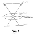
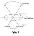
- Two such techniques are illustrated schematically in FIGS. 1 and 2 .
- the Twinning technique illustrated in FIG. 1 , involves simultaneous, linear x-ray tube and detector motions, about a fulcrum in the object plane, to produce an image of the object that has only one object plane in sharp focus. The projections of features from all other planes are blurred.
- section thickness is inversely proportional to the amplitude of motion (in degrees) of the x-ray source.
- the Grossman technique illustrated in FIG. 2 , is similar to the Twinning technique but involves a rotational movement of the x-ray tube and detector, again as a unit about a fulacrum point but of a fixed distance from each other. With both of these techniques, one or more exposures are necessary for each topography plane that is imaged as well as full motion of the x-ray tube and detector through the tomographic angle.
- US-A-4,504,962 discloses a system for performing digital tomosynthesis on an object region having the features of the preamble of claim 1.
- the present invention is characterized by the features of the characterizing portion of claim 1.
- Optional features are recited in the dependent claims.
- US 4 132 896 discloses a system for digital tomosynthesis which uses a stationary detector and a linear source trajectory.
- the present invention is a new system and method for tomosynthesis x-ray imaging.
- a system in accordance with the invention includes an x-ray source, a digital detector (or its equivalent) in an image plane, a digital image data processor, and a controller.
- the x-ray source and detector are disposed on opposite sides of an object region disposed about an object plane parallel to the image plane.
- the source faces the detector so that x-rays from the source are directed toward and through the object region to the detector.
- the controller effects motion of the source along an arc opposite the detector.
- the detector As the source moves along the arc, the detector generates for a succession of points along the arc, a corresponding succession of image data sets, each set being representative of the intensity of x-rays incident on the detector for the then current position of the source.
- the image data processor is responsive to the image data sets to generate an output image signal representative of the x-ray absorption within the object region. To do so, the processor transforms the image data to a form corresponding to that which would have been generated had the x-ray source moved in a linear motion in a source plane parallel to the image plane, rather than an arc.
- the resultant image data thus corresponds in form to that produced by a conventional linear motion, e.g., Twinning-type, system, so that conventional techniques may be used to produce a final representation of the x-ray absorption of the object region.
- the invention utilizes a rotating x-ray tube and a stationary digital detector.
- the prior art by way of contrast, utilizes moving detectors.
- One primary difference between the invention and previously described methods is the use of a stationary detector. This technique allows the reconstruction of any tomographic plane of an object region with the x-ray tube moving in an arc above the object, while a planar detector and an object region (or patient) are stationary, permitting the formation of tomographic images.
- the invention has the advantage that it may be easily applied to digital x-ray equipment that is already in use.
- Another advantage of the invention is that the detector is stationary with respect to the object being imaged, thereby eliminating one source of position uncertainty.
- any plane in the object that is parallel to the image plane may be reconstructed from a single set of images; whereas, in the prior art, each reconstructed plane in the object requires acquisition of a new set of images.
- tomosynthesis techniques applied to mammography a radiologist can look through a series of tomographic images and determine if a suspicious area is real or is due to the superimposition of structures. If real, tomosynthesis will present a better image of the lesion by reducing the noise from the superimposed structures. A radiologist accordingly has increased confidence in classifying lesions, which would be expected to reduce the number of biopsies of benign lesions.
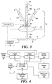
- FIG. 3 A system 4 embodying the invention is shown in FIG. 3 .
- the system 4 includes a controller 8, a digital image processor 10, an x-ray source 12, and a planar digital x-ray detector 14 lying in an image plane IP.
- a support structure 16 supports the source 12 with respect to the detector 14, so that x-rays from the source 12 are directed toward the detector 14, as described below.
- An object region 20 is defined between the source 12 and the detector 14 and extending along and about an object plane OP, and in the path of x-rays passing from source 12 to the detector 14.
- the detector 14 is a digital detector lying in an image plane IP, having a two dimensional planar array of x-ray detector elements.
- the support structure 16 is articulated, and includes a first portion 16A and a second portion 16B.
- Portion 16A extends from a proximal end 16a in a direction along an axis A, which is perpendicular to the image plane IP, to a distal end 16b and the second portion 16B extends from the distal end 16b of the first portion 16A along an axis B to the x-ray source 12.
- the first portion 16A and second portion 16B are pivotally coupled about an axis P at the distal end of portion 16A, where axis P is perpendicular to axis A.
- An actuator 30 is selectively controlled to determine the angle of portion 16B (and axis B) with respect to portion 16A (and axis A), in response to control signals from controller 8. While in the present embodiment, the axis P is between the object plane OP and the source 12, the axis P may be at or below the object plane in other embodiments.
- the x-ray source 12 and support structure 16 may be a General Electric Medical Systems Model DMR Mammography System.
- the controller 8 is a digital computer which is programmed to control the angular position of portion 16B with respect to portion 16A (and thus the position of source 12).
- the image data processor 10 is also preferably a digital computer programmed to the process data produced by the detector 14 in response to incident x-rays. Such a processor 10 can, in addition, function to control the emission of x-rays from source 12 such as by techniques known in the art. In other embodiments, a single programmed computer may perform the functions of both controller 8 and processor 10.
- the detector 14 in the preferred embodiment is a planar, or flat-field, detector including a two dimensional planar array of x-ray detection elements or pixels.
- Each of those pixel elements may include a scintillator element (which is responsive to incident x-rays to produce light photons) and a photodiode, which in turn produces a digitized signal representation of the x-ray flux incident on the scintillator element of that detector element.
- Other types of digital x-ray detectors may be used, flat or curved.
- Each of the pixel elements is interrogated by the processor 10 to provide at processor 10 digital data representative of the distribution of x-ray intensities at the image plane IP.
- the pixel elements of detector 14 are part of a small geometry integrated circuit array, so that a high resolution image representation may be obtained.
- a charge coupled device (CCD) or a direct digital detector can be used.
- the digital image processor 10 may be a conventional digital computer programmed to perform the transformations described below.
- FIG. 4 shows an exemplary configuration of a similar computer 10'.
- the computer 10' of FIG. 4 includes a digital arithmetic unit 21, digital image memory 22, a x-ray controller 24, and digital disk storage 26.
- the digital arithmetic unit 21 interfaces with digital image data 28; while the controller 24 interfaces with actuator 30, Figure 3 , driving the support structure so as to move the source 12 to correct angular locations.
- the computer 10 can further include a display section 10a; or it can command video on a separate monitor 10b.
- the controller 24 can also be connected to drive other devices, such as a multiformat camera 10c; and the controller 24 can further command and control irradiation by the x-ray source such as through control signals 29.
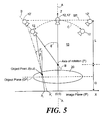
- FIG. 5 shows an operational representation of the system 10 of FIG. 4 controlling the irradiation of the object 20 and image plane IP with x-ray radiation generated by the source 12.
- the angle ⁇ is given by the angle of the support arm 16B, FIG. 3 , relative to the perpendicular to the image plane IP.
- an angle ⁇ is defined as the angle of the x-rays intersecting the point J(x,z) relative to the perpendicular to the image plane IP.
- the point x is the projection of the object point J(x,z) onto the image plane IP:
- the perpendicular distance of the focal spot from the image plane depends on the angle ⁇ . This is in contrast to images that are formed based on the Twinning principle, where the focal spot moves in a horizontal source plane SP parallel to the image plane IP.
- the image that is formed by rotation of the tube is transformed to construct a new image that approximates that which would have been formed if the focal spot were moved in a source plane SP parallel to the image plane IP i.e. along broken line SP as shown in FIG. 5 .
- This new image data is utilized to reconstruct a tomographic plane in the object by a simple shifting and addition of image data sets.
- the x-ray gantry thus produces images with image points as defined by Eq. 2. For every x i in the image, a known value of ⁇ is used with a selected z to determine an object point x from Eq. 2. The values of ⁇ , x, and z are then applied to Eq. 5 to determine a value for x i ' in the new image. The set of new images produced are then utilized to reconstruct a tomographic plane OP at z by a simple linear shifting process analogous to the Twinning method.
- the technique for construction of a new set of images for each desired tomographic plane results in a small distortion of image information for structures outside the plane OP. This is because the x-ray paths through the object 20 that occur with rotation of the focal spot about an axis P are slightly different from those that occur when the focal spot is moved within a horizontal plane.
- the distortion for all points that lie exactly on the reconstructed plane OP is zero.
- the maximal distortion for an object positioned 5 cm above the reconstructed is approximately 195 microns.
- the linear tomographic shift for this imaging geometry is approximately 7,606 microns, this distortion corresponds 2.5% of the tomographic shift.
- the magnitude of the distortion caused by creation of the new image is small compared to the amount of linear shift utilized for the tomographic reconstruction. For this reason, distortion produced by the invention does not have a significant effect on the tomographic image quality.
- the invention is thus particularly useful in imaging breasts utilizing a full field digital mammography system.
- Tomosynthesis in this manner allows reconstruction of "in-focus" tomographic planes at any level in the breast.
- the radiation dose is low and comparable to a single-view conventional mammogram.
- Preliminary results indicate that the visibility of masses is increased with tomosynthesis according to the invention.
- Tomosynthesis of the invention further has the potential to improve the specificity of mammography with improved lesion margin visibility and to improve early breast cancer detection, especially for women with radiographically dense breasts.
- the invention provides advantages which allow the radiologist to see through "structured noise" of normal breast tissue so as to improve detection and characterization of the breast cancer.
- the x-ray source and the film-screen detector move in opposite directions, so that only features in one plane of the image remain in sharp focus.
- multiple images are acquired as the x-ray tube, i.e., the "source” 60, is moved in an are 61 above the stationary breast 62 and detector 63.
- the images obtained at each angle ⁇ by the detector 63 are of low radiation dose, with the total radiation dose for all of the images being equivalent to, or slightly higher than, the dose used for a standard single view mammogram.
- the source 12 spans an arc C defined by angle ⁇ and within a plane 13 formed by axes X and Z.
- the plane 13 preferably extends through approximately the centers of the object 20 and the detector or image plane IP.
- the invention preferably makes use of full-field flat digital detectors that exhibit rapid readout times. Such detectors make tomosynthesis imaging of the breast practical in clinical settings because of low noise, large flat surface area with minimal image distortion, and rapid image readout times.
- FIG. 7 illustrates one system 70, constructed according to the invention, which utilizes a General Electric model DMR mammography gantry 71 with a full-field digital image receptor 72.
- the system allows imaging at any angle ⁇ up to +/- 27 degrees from the perpendicular to the detector 72.
- the x-ray source 73 pivots from an arm 75 and about a point 74 above the detector 72.
- the x-ray source 73 is stationary during the exposure and then is moved to the next position before obtaining the next image.
- the motion of the x-ray source is motorized and controlled by a computer; however, the source can also be moved manually.
- the digital detector 72 is composed of a Cesium Iodide (CsI) phosphor on an amorphous-silicon transistor/photodiode array by General Electric Corporation.
- This detector 72 has a pixel pitch of one hundred microns and the image readout time is three hundred milliseconds.
- the invention preferably incorporates an actuator or control mechanism 76 to determine and acquire a selected angle ⁇ of the arm 75.
- the angle ⁇ can be determined with a Lucas Control System Products (Hampton, VA) high resolution precision inclinometer (model 02538-01) with a range of +/-20 degrees and an accuracy of +/-0.1 degrees from zero to ten degrees, and +/-1% for ten to twenty degrees.
- VA Lucas Control System Products
- VA high resolution precision inclinometer
- FIG. 8 illustrates the acquisition of tomosynthesis projection images, according to the invention, from discrete x-ray source positions 82a-d along an arc 84 above the target breast 81.
- the source 80 can be moved to any number of x-ray source positions 82 selectively.
- Tomosynthesis images of any plane 83 in the breast 81 are then reconstructed using the methods described herein.
- the projection images 85a-d from the x-ray source positions 82a-d are transformed by a digital processor 86 to simulate images 87a-8d that would be obtained from an x-ray source located at positions 82a' - 82d'.
- the detector 88 does not move; rather, detector motion is simulated by shifting the images 87 in the computer 86.
- the transformation and shifting algorithms are repeated, if desired, to reconstruct the tomography image 89 for any plane 83 along the Z axis above the detector 88.
- the mathematical reconstruction algorithms to obtain the image 89 were previously described.
- Typical images obtained through a system of the invention can be made at 26-30kVp, 10-40mAs per view, and six to ten views between about +/-20 degrees (i.e., range of the angle ⁇ ).
- the summed mean glandular radiation dosage for the tomosynthesis images can be, for example, larger than or less than that of the conventional film-screen image.
- Tomosynthesis images of the invention can be reconstructed, for example, on a Sun Microsystems Sparc 20 workstation. After initial images are acquired for each angle ⁇ , reconstructed tomography images at 1.5 to 3 mm spacing can be made to acquire in-focus images of entire breasts.
- images are acquired at discrete tube positions, rather than continuously as the tube moved such as in the prior art. Consequently, the blurring of structures is not a smooth blurring typical of continuous image acquisition. For example, if nine images are used in the tomosynthesis data set, objects above or below the in-focus plane will be displayed as nine separate objects in the reconstructed image. Each object will have approximately one ninth the contrast of the original object. For high contrast objects such as a large calcification, nine images of the calcification may be visible. Image structures outside of the in-focus plane are essentially repeated in the direction of x-ray source motion. High frequency information is retained, although the contrast of out-of plane structures in greatly reduced.
- the reconstructed image can be improved further.
- self-masking tomosynthesis reduces low frequency information in the direction of the x-ray source motion.
- other image processing methods can also be used to reduce the contribution of out-of-focus structures such as from planes above or below the in-focus plane.
- one suitable technique identifies the plane of an out-of-focus structure such as a dense calcification and computes its contribution to all other planes. The image of the structure is then removed from all planes except the plane containing the structure "in-focus".
- tomosynthesis may prove to be a valuable screening tool for women with radiographically dense breasts.
- the ability to "see into the middle of the breast” by blurring the superimposed structures can permit significant improvements in the sensitivity of mammography screening in the early detection of breast cancer.
- Tomosynthesis according to the invention may also have the potential to detect cancers in dense breasts or multi focal cancers at a small fraction of the cost of magnetic resonance imaging.
- Tomosynthesis of the invention may also be used for problem solving or diagnostic breast imaging.
- Current mammographic techniques have poor specificity, since 70-90% of all breast biopsies are negative, whereas tomosynthesis of the invention may provide the radiologist with an improved image of a potential lesion.
- the invention can also provide advantages in providing a radiologist with greater confidence in lesion classification and in decreasing the number of benign biopsies.
- the invention further facilitates performing the entire diagnostic evaluation of a lesion with diagnostic examinations, saving time and reducing patient radiation exposure.
- tomosynthesis according to the invention will provide three dimensional information concerning the dimensions of a lesion, whether micro calcifications are associated with a mass, and how they are distributed.
- the three dimensional distribution of calcifications is thought to be a useful indicator in discriminating benign versus malignant lesions and thus may also have a positive impact on clinical patient management.
- the tomosynthesis methods of the invention are adaptable to current mammography systems with minor modifications.
- the image acquisition geometry of the invention has several advantages: 1) there are no moving parts near the breast or abdomen, 2) existing mammography machines may be easily altered to allow this type of motion, since many already provide the ability for the tube to move in an arc above the breast, and 3) a unit modified to do tomosynthesis imaging will still be completely useable for routine breast imaging, thereby eliminating the need for a dedicated tomosynthesis system.
- Motorized motion of the x-ray tube allows for the acquisition of all of the tomosynthesis images in approximately three to five seconds, a time which is sufficiently rapid to make the system clinically applicable since these exposure times are similar to magnification views with current systems.
Landscapes
- Health & Medical Sciences (AREA)
- Life Sciences & Earth Sciences (AREA)
- Engineering & Computer Science (AREA)
- Medical Informatics (AREA)
- Physics & Mathematics (AREA)
- Pathology (AREA)
- Molecular Biology (AREA)
- Biophysics (AREA)
- High Energy & Nuclear Physics (AREA)
- Veterinary Medicine (AREA)
- Nuclear Medicine, Radiotherapy & Molecular Imaging (AREA)
- Optics & Photonics (AREA)
- Public Health (AREA)
- Radiology & Medical Imaging (AREA)
- Biomedical Technology (AREA)
- Heart & Thoracic Surgery (AREA)
- General Health & Medical Sciences (AREA)
- Surgery (AREA)
- Animal Behavior & Ethology (AREA)
- Mathematical Physics (AREA)
- General Physics & Mathematics (AREA)
- Theoretical Computer Science (AREA)
- Dentistry (AREA)
- Oral & Maxillofacial Surgery (AREA)
- Apparatus For Radiation Diagnosis (AREA)
- Image Processing (AREA)
- Image Analysis (AREA)
Abstract
Claims (22)
- Système permettant de réaliser une tomosynthèse numérique sur une région à examiner, comprenant :un détecteur de rayons X (14) adapté pour détecter un rayonnement X transmis à travers la région à examiner (20) et produire des données d'imagerie représentatives de l'intensité du rayonnement ;une source de rayons X mobile (12) adaptée pour générer le rayonnement X ;une commande de déplacement (S) adaptée pour déplacer la source de rayons X dans une pluralité de positions définissant un arc (C) autour de la région ; etun processeur de données (10) adapté pour déterminer des points d'absorption des rayons X à l'intérieur de la région sur la base d'un ensemble de données d'imagerie contenant des données d'imagerie qui correspondent à chacune des positions dans lesquelles le détecteur de rayons X (14) est fixe et l'arc (C) se situe dans un plan (13) et possède un axe de rotation (P) sur une ligne (A) du plan qui est perpendiculaire au détecteur (14) et qui passe approximativement par le centre dudit détecteur ;caractérisé en ce que :la région à examiner (20) est disposée autour d'un plan d'objet (OP), le processeur de données (10) comprenant en plus des moyens pour transformer les données d'imagerie en une forme représentative de l'intensité attendue du rayonnement X généré par la source dans une position décalée (12') définie par l'intersection entre :a) une ligne (SP) du plan (13) de l'arc (C) qui est sensiblement parallèle au plan d'objet (OP) etb) une ligne (B) du plan (13) de l'arc (C) définie par l'axe de rotation (P) et par l'une des positions de la source de rayons X (12) correspondant aux données d'imagerie.
- Système selon la revendication 1, dans lequel le processeur de données comprend des moyens pour générer un signal d'image qui représente la région sous la forme d'une carte des points dans l'espace, chaque point définissant l'absorptivité du rayonnement X dans la région.
- Système selon la revendication 1, dans lequel l'intersection entre l'axe de rotation (P) et le plan (13) de l'arc (C) définit un centre de rotation qui se trouve entre la source (12) et le détecteur (14).
- Système selon la revendication 1, dans lequel la ligne qui est sensiblement parallèle au plan d'objet (OP) est également tangente à l'arc (C).
- Système selon la revendication 1, dans lequel la source (12) comprend un tube à rayons X.
- Système selon la revendication 1, dans lequel le détecteur (14) comprend un réseau d'éléments détecteurs de rayons X et dans lequel les données d'imagerie comprennent une pluralité de valeurs de données d'intensité dont chacune correspond au rayonnement X détecté par chacun desdits éléments.
- Système selon la revendication 1, dans lequel le détecteur (14) comprend un réseau d'éléments détecteurs en deux dimensions et dans lequel les données d'imagerie comprennent une pluralité de valeurs de données d'intensité dont chacune correspond à chacun des éléments.
- Système selon la revendication 1, dans lequel la commande (8) comprend une première structure support rigide qui présente (16A) une extrémité proximale située à peu près à un centre de rotation de l'arc et une extrémité distale pour supporter rigidement le détecteur (14).
- Système selon la revendication 8, dans lequel la commande (8) comprend une deuxième structure support rigide (16B) qui présente une première extrémité, reliée de manière à pouvoir pivoter à l'extrémité proximale de la première structure support (16A) au centre de rotation, et une deuxième extrémité pour supporter la source (12) à une distance fixe du centre de rotation, la source pouvant tourner autour du centre de rotation et se déplacer le long de l'arc.
- Système selon la revendication 9, dans lequel la source (12) est construite et disposée de façon à projeter le rayonnement X sensiblement dans l'alignement de la deuxième structure support (16B) et en direction du centre de rotation.
- Système selon la revendication 9, comprenant en plus un actionneur qui réagit aux signaux de positionnement angulaire envoyés par la commande (8) pour déplacer la source (12) à un angle formé entre la première et la deuxième structure support, ledit angle étant indicatif de l'une des positions.
- Système selon la revendication 9, dans lequel ladite commande (8) comprend des moyens pour déterminer un angle entre la première et la deuxième structure support.
- Système selon la revendication 1, dans lequel la commande (11) comprend des moyens pour déterminer un angle formé entre :a) une ligne (A) perpendiculaire au détecteur (14) et passant par un centre de rotation (P) de l'arc (C), etb) une ligne (B) définie par le centre de rotation (P) et un emplacement de la source (12) sur l'arc (C).
- Système selon la revendication 1, dans lequel la commande (8) comprend un calculateur doté de moyens permettant de commander sélectivement la position de la source (12) le long de l'arc (C).
- Système selon la revendication 1, dans lequel le processeur de données comprend un calculateur.
- Système selon la revendication 15, dans lequel le calculateur comprend en plus des moyens pour commander la commande de déplacement (8) de façon à déplacer la source (12) sélectivement le long de l'arc (C).
- Système selon la revendication 15, dans lequel la source (12) réagit aux signaux d'activation et désactivation sélective de la source envoyés par le calculateur.
- Système selon la revendication 1, dans lequel le détecteur (14) comprend une pluralité d'éléments scintillateurs et de photodétecteurs associés, chaque photodétecteur produisant un signal numérisé qui représente l'intensité du flux de rayons X pour l'un des éléments.
- Système selon la revendication 1, dans lequel le détecteur (14) comprend un réseau de circuits intégrés.
- Système selon la revendication 1, comprenant en plus un portique à rayons X (71) qui présentea) un premier bras (75) pour supporter la source (73) de façon qu'elle puisse pivoter autour du centre de rotation (74), etb) un deuxième bras pour supporter rigidement le détecteur (72) par rapport au centre de rotation (74).
- Système selon la revendication 20, comprenant en plus un calculateur pour commander le portique (71) de façon à déplacer la source (73) dans des positions sélectionnées correspondant à un angle formé entre le premier et le deuxième bras.
- Système selon la revendication 1, dans lequel le détecteur (14) comprend un luminophore à base d'iodure de césium sur un réseau de photodiodes en silicium amorphe.
Applications Claiming Priority (3)
| Application Number | Priority Date | Filing Date | Title |
|---|---|---|---|
| US2227696P | 1996-07-23 | 1996-07-23 | |
| US22276P | 1996-07-23 | ||
| PCT/US1997/012774 WO1998003115A1 (fr) | 1996-07-23 | 1997-07-22 | Systeme de tomosynthese destine a l'imagerie des seins |
Publications (3)
| Publication Number | Publication Date |
|---|---|
| EP0932363A1 EP0932363A1 (fr) | 1999-08-04 |
| EP0932363A4 EP0932363A4 (fr) | 2005-08-31 |
| EP0932363B1 true EP0932363B1 (fr) | 2010-09-15 |
Family
ID=21808761
Family Applications (1)
| Application Number | Title | Priority Date | Filing Date |
|---|---|---|---|
| EP97936989A Expired - Lifetime EP0932363B1 (fr) | 1996-07-23 | 1997-07-22 | Systeme de tomosynthese destine a l'imagerie des seins |
Country Status (5)
| Country | Link |
|---|---|
| US (1) | US5872828A (fr) |
| EP (1) | EP0932363B1 (fr) |
| JP (2) | JP4458553B2 (fr) |
| DE (1) | DE69739995D1 (fr) |
| WO (1) | WO1998003115A1 (fr) |
Cited By (1)
| Publication number | Priority date | Publication date | Assignee | Title |
|---|---|---|---|---|
| CN106419947A (zh) * | 2015-08-04 | 2017-02-22 | 通用电气公司 | 用于层析x射线照相组合图像采集的系统以及方法 |
Families Citing this family (160)
| Publication number | Priority date | Publication date | Assignee | Title |
|---|---|---|---|---|
| US6289235B1 (en) | 1998-03-05 | 2001-09-11 | Wake Forest University | Method and system for creating three-dimensional images using tomosynthetic computed tomography |
| US6081577A (en) * | 1998-07-24 | 2000-06-27 | Wake Forest University | Method and system for creating task-dependent three-dimensional images |
| US6375352B1 (en) * | 1999-10-01 | 2002-04-23 | General Electric Company | Apparatus and method for obtaining x-ray tomosynthesis data for mammography |
| US6222902B1 (en) * | 1998-11-25 | 2001-04-24 | Picker International, Inc. | Real-time tomographic system with flat panel detectors |
| US6292531B1 (en) * | 1998-12-31 | 2001-09-18 | General Electric Company | Methods and apparatus for generating depth information mammography images |
| US6292530B1 (en) * | 1999-04-29 | 2001-09-18 | General Electric Company | Method and apparatus for reconstructing image data acquired by a tomosynthesis x-ray imaging system |
| US6744848B2 (en) | 2000-02-11 | 2004-06-01 | Brandeis University | Method and system for low-dose three-dimensional imaging of a scene |
| US6443156B1 (en) | 2000-08-02 | 2002-09-03 | Laura E. Niklason | Separable double lumen endotracheal tube |
| US6671349B1 (en) | 2000-11-13 | 2003-12-30 | Olganix Corporation | Tomosynthesis system and registration method |
| US6748046B2 (en) * | 2000-12-06 | 2004-06-08 | Teradyne, Inc. | Off-center tomosynthesis |
| FI117317B (fi) * | 2001-04-20 | 2006-09-15 | Instrumentarium Corp | Kuvainformaation muodostaminen, mammografialaite ja biopsian suorittaminen |
| JP2004535858A (ja) * | 2001-05-16 | 2004-12-02 | コーニンクレッカ フィリップス エレクトロニクス エヌ ヴィ | 三次元データーセットを可視化するための方法及び装置 |
| US7085406B2 (en) * | 2001-07-27 | 2006-08-01 | General Electric Company | Method and system for unsupervised transfer function generation for images of rendered volumes |
| US6611575B1 (en) | 2001-07-27 | 2003-08-26 | General Electric Company | Method and system for high resolution 3D visualization of mammography images |
| WO2003020114A2 (fr) * | 2001-08-31 | 2003-03-13 | Analogic Corporation | Procede et systeme de positionnement d'image pour tomosynthese dans un systeme de radiographie numerique a rayons x |
| US6978040B2 (en) * | 2001-12-19 | 2005-12-20 | Canon Kabushiki Kaisha | Optical recovery of radiographic geometry |
| US20030149364A1 (en) * | 2002-02-01 | 2003-08-07 | Ajay Kapur | Methods, system and apparatus for digital imaging |
| US7218766B2 (en) * | 2002-04-15 | 2007-05-15 | General Electric Company | Computer aided detection (CAD) for 3D digital mammography |
| US6724856B2 (en) * | 2002-04-15 | 2004-04-20 | General Electric Company | Reprojection and backprojection methods and algorithms for implementation thereof |
| US6707878B2 (en) | 2002-04-15 | 2004-03-16 | General Electric Company | Generalized filtered back-projection reconstruction in digital tomosynthesis |
| US7783089B2 (en) * | 2002-04-15 | 2010-08-24 | General Electric Company | Method and apparatus for providing mammographic image metrics to a clinician |
| US6882700B2 (en) * | 2002-04-15 | 2005-04-19 | General Electric Company | Tomosynthesis X-ray mammogram system and method with automatic drive system |
| US20030194050A1 (en) * | 2002-04-15 | 2003-10-16 | General Electric Company | Multi modality X-ray and nuclear medicine mammography imaging system and method |
| US6710349B2 (en) * | 2002-04-16 | 2004-03-23 | General Electric Company | Edge resolved dual scintillator gamma ray detection system and method |
| US6748047B2 (en) * | 2002-05-15 | 2004-06-08 | General Electric Company | Scatter correction method for non-stationary X-ray acquisitions |
| US7149335B2 (en) * | 2002-09-27 | 2006-12-12 | General Electric Company | Method and apparatus for enhancing an image |
| US6970531B2 (en) * | 2002-10-07 | 2005-11-29 | General Electric Company | Continuous scan RAD tomosynthesis system and method |
| US6940943B2 (en) * | 2002-10-07 | 2005-09-06 | General Electric Company | Continuous scan tomosynthesis system and method |
| JP3667317B2 (ja) * | 2002-11-26 | 2005-07-06 | キヤノン株式会社 | 放射線断層撮影装置 |
| US10638994B2 (en) * | 2002-11-27 | 2020-05-05 | Hologic, Inc. | X-ray mammography with tomosynthesis |
| US7616801B2 (en) * | 2002-11-27 | 2009-11-10 | Hologic, Inc. | Image handling and display in x-ray mammography and tomosynthesis |
| US8571289B2 (en) | 2002-11-27 | 2013-10-29 | Hologic, Inc. | System and method for generating a 2D image from a tomosynthesis data set |
| US8565372B2 (en) | 2003-11-26 | 2013-10-22 | Hologic, Inc | System and method for low dose tomosynthesis |
| US7577282B2 (en) | 2002-11-27 | 2009-08-18 | Hologic, Inc. | Image handling and display in X-ray mammography and tomosynthesis |
| US7123684B2 (en) * | 2002-11-27 | 2006-10-17 | Hologic, Inc. | Full field mammography with tissue exposure control, tomosynthesis, and dynamic field of view processing |
| US7110490B2 (en) * | 2002-12-10 | 2006-09-19 | General Electric Company | Full field digital tomosynthesis method and apparatus |
| US7356113B2 (en) * | 2003-02-12 | 2008-04-08 | Brandeis University | Tomosynthesis imaging system and method |
| US6888924B2 (en) * | 2003-06-25 | 2005-05-03 | General Electric Company | Method, apparatus, and medium for calibration of tomosynthesis system geometry using fiducial markers with non-determined position |
| US6862337B2 (en) | 2003-06-25 | 2005-03-01 | General Electric Company | Linear track based digital tomosynthesis system and method |
| US6904121B2 (en) * | 2003-06-25 | 2005-06-07 | General Electric Company | Fourier based method, apparatus, and medium for optimal reconstruction in digital tomosynthesis |
| US7433507B2 (en) * | 2003-07-03 | 2008-10-07 | Ge Medical Systems Global Technology Co. | Imaging chain for digital tomosynthesis on a flat panel detector |
| US6885724B2 (en) * | 2003-08-22 | 2005-04-26 | Ge Medical Systems Global Technology Company, Llc | Radiographic tomosynthesis image acquisition utilizing asymmetric geometry |
| JP4603823B2 (ja) * | 2003-10-14 | 2010-12-22 | キヤノン株式会社 | 放射線撮像装置、放射線撮像方法及びプログラム |
| DE10353611B4 (de) * | 2003-11-17 | 2013-01-17 | Siemens Aktiengesellschaft | Röntgendiagnostikgerät für Mammographieuntersuchungen |
| US8768026B2 (en) | 2003-11-26 | 2014-07-01 | Hologic, Inc. | X-ray imaging with x-ray markers that provide adjunct information but preserve image quality |
| WO2005055803A2 (fr) * | 2003-12-03 | 2005-06-23 | The General Hospital Corporation D/B/A Massachusetts General Hospital | Systeme et procede pour la reconstitution de faisceau conique multisegment en imagerie par tomosynthese |
| US8340373B2 (en) * | 2003-12-23 | 2012-12-25 | General Electric Company | Quantitative image reconstruction method and system |
| US7653229B2 (en) * | 2003-12-23 | 2010-01-26 | General Electric Company | Methods and apparatus for reconstruction of volume data from projection data |
| US7177390B2 (en) * | 2004-03-11 | 2007-02-13 | Trex Enterprises Corp | Digital x-ray tomosynthesis system |
| US7142633B2 (en) * | 2004-03-31 | 2006-11-28 | General Electric Company | Enhanced X-ray imaging system and method |
| CN1953708B (zh) * | 2004-05-14 | 2010-06-16 | 皇家飞利浦电子股份有限公司 | 用于诊断乳腺癌的系统和方法 |
| US8774355B2 (en) * | 2004-06-30 | 2014-07-08 | General Electric Company | Method and apparatus for direct reconstruction in tomosynthesis imaging |
| FR2875693B1 (fr) * | 2004-09-24 | 2006-12-08 | Gen Electric | Dispositif de tomographie par rayons x |
| US7662082B2 (en) | 2004-11-05 | 2010-02-16 | Theragenics Corporation | Expandable brachytherapy device |
| EP2602743B1 (fr) | 2004-11-15 | 2014-11-05 | Hologic, Inc. | Affichage et génération de géométrie de mise en correspondance de mammographies et d'images de tomosynthèse |
| EP3106094B1 (fr) | 2004-11-26 | 2021-09-08 | Hologic, Inc. | Systeme radiographique multimode integrant mammographie/tomosynthese |
| US20060210131A1 (en) * | 2005-03-15 | 2006-09-21 | Wheeler Frederick W Jr | Tomographic computer aided diagnosis (CAD) with multiple reconstructions |
| US20060215809A1 (en) * | 2005-03-22 | 2006-09-28 | General Electric Company | System and method for motion and angulation profiles in tomosynthesis |
| DE102005026578A1 (de) * | 2005-06-08 | 2006-12-21 | Comet Gmbh | Vorrichtung zur Röntgen-Laminographie und/oder Tomosynthese |
| US20070014468A1 (en) * | 2005-07-12 | 2007-01-18 | Gines David L | System and method for confidence measures for mult-resolution auto-focused tomosynthesis |
| US7245698B2 (en) * | 2005-07-13 | 2007-07-17 | Siemens Medical Solutions Usa, Inc. | 4-dimensional digital tomosynthesis and its applications in radiation therapy |
| US7505554B2 (en) * | 2005-07-25 | 2009-03-17 | Digimd Corporation | Apparatus and methods of an X-ray and tomosynthesis and dual spectra machine |
| US7298816B2 (en) * | 2005-08-02 | 2007-11-20 | The General Hospital Corporation | Tomography system |
| US7764820B2 (en) * | 2005-08-24 | 2010-07-27 | The General Hospital Corporation | Multi-threshold peripheral equalization method and apparatus for digital mammography and breast tomosynthesis |
| EP1937149A1 (fr) * | 2005-10-19 | 2008-07-02 | The General Hospital Corporation | Système d'imagerie et techniques associées |
| DE202005017496U1 (de) * | 2005-11-07 | 2007-03-15 | Comet Gmbh | Target für eine Mikrofocus- oder Nanofocus-Röntgenröhre |
| US10008184B2 (en) | 2005-11-10 | 2018-06-26 | Hologic, Inc. | System and method for generating a 2D image using mammography and/or tomosynthesis image data |
| US8079946B2 (en) | 2005-11-18 | 2011-12-20 | Senorx, Inc. | Asymmetrical irradiation of a body cavity |
| US7573977B2 (en) * | 2006-01-31 | 2009-08-11 | Kabushiki Kaisha Toshiba | Mammographic apparatus |
| DE102006005068A1 (de) * | 2006-02-03 | 2007-08-09 | Siemens Ag | Positionsvorrichtung für ein Mammografiegerät |
| WO2007095330A2 (fr) | 2006-02-15 | 2007-08-23 | Hologic Inc | Biopsie mammaire et localisation a l'aiguille a l'aide de systemes de tomosynthese |
| JP2007229201A (ja) * | 2006-03-01 | 2007-09-13 | View Magic:Kk | 立体マンモグラフィ装置 |
| DE102006012407A1 (de) * | 2006-03-17 | 2007-09-20 | Siemens Ag | Tomosynthetisches Bildrekonstruktionsverfahren und mit diesem Verfahren arbeitende diagnostische Einrichtung |
| DE102006024413A1 (de) * | 2006-05-24 | 2007-11-29 | Siemens Ag | Verfahren und Einrichtung zum Erzeugen eines tomosynthetischen 3D-Röntgenbildes |
| US20080037703A1 (en) * | 2006-08-09 | 2008-02-14 | Digimd Corporation | Three dimensional breast imaging |
| US7920729B2 (en) * | 2006-08-10 | 2011-04-05 | General Electric Co. | Classification methods and apparatus |
| US7787677B2 (en) * | 2006-08-16 | 2010-08-31 | Mevis Breastcare Gmbh & Co. Kg | Presentation method, presentation device and computer program for presenting an image of an object |
| FR2909207B1 (fr) * | 2006-11-24 | 2009-01-30 | Gen Electric | Procede de visualisation tridimensionnelle d'images de tomosynthese en mammographie. |
| US7817773B2 (en) * | 2007-01-05 | 2010-10-19 | Dexela Limited | Variable speed three-dimensional imaging system |
| JP2008237631A (ja) * | 2007-03-28 | 2008-10-09 | Fujifilm Corp | 放射線画像撮像装置 |
| DE102007020642A1 (de) * | 2007-04-30 | 2008-11-06 | Dürr Dental GmbH & Co. KG | Röntgengerät sowie Sensoreinheit für ein Röntgengerät |
| SE0702061L (sv) * | 2007-09-17 | 2009-03-18 | Xcounter Ab | Metod för att skapa, visa och analysera röntgenbilder och anordning för att implementera metoden |
| US7630533B2 (en) | 2007-09-20 | 2009-12-08 | Hologic, Inc. | Breast tomosynthesis with display of highlighted suspected calcifications |
| US7936858B2 (en) * | 2007-09-28 | 2011-05-03 | Siemens Medical Solutions Usa, Inc. | System and method for tomosynthesis |
| US7929743B2 (en) * | 2007-10-02 | 2011-04-19 | Hologic, Inc. | Displaying breast tomosynthesis computer-aided detection results |
| DE102007049539B4 (de) * | 2007-10-16 | 2017-07-20 | Siemens Healthcare Gmbh | Vorrichtung und Verfahren zur Bearbeitung und Darstellung von Röntgenbildern |
| DE102008009128B4 (de) * | 2008-02-14 | 2014-11-06 | Siemens Aktiengesellschaft | Tomosynthetisches Bildrekonstruktionsverfahren und mit diesem Verfahren arbeitende diagnostische Einrichtung |
| DE102008018269A1 (de) | 2008-04-10 | 2009-10-29 | Fraunhofer-Gesellschaft zur Förderung der angewandten Forschung e.V. | Vorrichtung und Verfahren zur rotationsfreien Computertomographie |
| US7724870B2 (en) | 2008-05-30 | 2010-05-25 | Siemens Medical Solutions Usa, Inc. | Digital tomosynthesis in robotic stereotactic radiosurgery |
| US7792245B2 (en) * | 2008-06-24 | 2010-09-07 | Hologic, Inc. | Breast tomosynthesis system with shifting face shield |
| JP4504442B2 (ja) * | 2008-07-08 | 2010-07-14 | 株式会社東芝 | X線診断装置 |
| US7991106B2 (en) | 2008-08-29 | 2011-08-02 | Hologic, Inc. | Multi-mode tomosynthesis/mammography gain calibration and image correction using gain map information from selected projection angles |
| US8515005B2 (en) | 2009-11-23 | 2013-08-20 | Hologic Inc. | Tomosynthesis with shifting focal spot and oscillating collimator blades |
| CN102176866B (zh) * | 2008-11-24 | 2013-10-16 | 霍罗吉克公司 | 控制用于体层合成和乳房x射线照相术成像的x射线焦斑特性的方法和系统 |
| US9579524B2 (en) | 2009-02-11 | 2017-02-28 | Hologic, Inc. | Flexible multi-lumen brachytherapy device |
| US9248311B2 (en) | 2009-02-11 | 2016-02-02 | Hologic, Inc. | System and method for modifying a flexibility of a brachythereapy catheter |
| US10207126B2 (en) | 2009-05-11 | 2019-02-19 | Cytyc Corporation | Lumen visualization and identification system for multi-lumen balloon catheter |
| US20110006224A1 (en) * | 2009-07-09 | 2011-01-13 | Maltz Jonathan S | Digital Tomosynthesis in Ion Beam Therapy Systems |
| US8254518B2 (en) * | 2009-10-05 | 2012-08-28 | Siemens Medical Solutions Usa, Inc. | Acquisition of projection images for tomosynthesis |
| EP2485651B1 (fr) | 2009-10-08 | 2020-12-23 | Hologic, Inc. | Système de ponction-biopsie du sein |
| JP2011172847A (ja) * | 2010-02-25 | 2011-09-08 | Fujifilm Corp | 放射線画像生成装置及び放射線画像生成方法 |
| JP2011177456A (ja) * | 2010-03-04 | 2011-09-15 | Fujifilm Corp | 放射線画像撮影方法及びその装置並びに放射線画像生成方法及びその装置 |
| KR101687971B1 (ko) * | 2010-07-19 | 2016-12-21 | 삼성전자주식회사 | 유방 촬영 장치 및 그 방법 |
| DE102010035920A1 (de) * | 2010-08-31 | 2012-03-01 | Siemens Aktiengesellschaft | Verfahren zur Darstellung eines vorbestimmten Volumenabschnitts eines Untersuchungsobjekts mittels eines Tomosynthesegeräts und entsprechendes Tomosynthesegerät |
| US9352172B2 (en) | 2010-09-30 | 2016-05-31 | Hologic, Inc. | Using a guide member to facilitate brachytherapy device swap |
| EP2624761B1 (fr) | 2010-10-05 | 2021-07-14 | Hologic, Inc. | Imagerie du sein par rayon x en position debout avec un mode de tomodensitométrie, de multiples modes de tomosynthèse et un mode de mammographie |
| WO2015054518A1 (fr) | 2013-10-09 | 2015-04-16 | Hologic, Inc | Tomosynthèse du sein à rayons x améliorant la résolution spatiale y compris dans le sens de l'épaisseur du sein aplati |
| WO2012067607A1 (fr) * | 2010-11-16 | 2012-05-24 | Analogic Corporation | Acquisition multimode d'images |
| US20120133600A1 (en) | 2010-11-26 | 2012-05-31 | Hologic, Inc. | User interface for medical image review workstation |
| US10342992B2 (en) | 2011-01-06 | 2019-07-09 | Hologic, Inc. | Orienting a brachytherapy applicator |
| CA2829349C (fr) | 2011-03-08 | 2021-02-09 | Hologic, Inc. | Systeme et procede pour une imagerie de seins a double energie et/ou a injection d'un agent de contraste pour un depistage, un diagnostic et une biopsie |
| FR2975277B1 (fr) | 2011-05-16 | 2014-08-08 | Gen Electric | Procede d'acquisition d'images medicales d'un organe et systeme d'imagerie medicale |
| JP5628092B2 (ja) * | 2011-05-25 | 2014-11-19 | 富士フイルム株式会社 | 画像処理装置、放射線画像撮影システム、画像処理プログラム、及び画像処理装置の作動方法 |
| WO2013004573A1 (fr) * | 2011-07-04 | 2013-01-10 | Koninklijke Philips Electronics N.V | Dispositif de limitation de champ, synchronisé avec un mouvement de balayage |
| US9449403B2 (en) | 2011-10-19 | 2016-09-20 | Siemens Aktiengesellschaft | Out of plane artifact reduction in digital breast tomosynthesis and CT |
| JP2014534042A (ja) | 2011-11-27 | 2014-12-18 | ホロジック, インコーポレイテッドHologic, Inc. | マンモグラフィーおよび/またはトモシンセシス画像データを使用して2d画像を生成するためのシステムおよび方法 |
| US9805507B2 (en) | 2012-02-13 | 2017-10-31 | Hologic, Inc | System and method for navigating a tomosynthesis stack using synthesized image data |
| ITBO20120227A1 (it) * | 2012-04-24 | 2013-10-25 | I M S Internaz Medico Scient Ifica S R L | Apparecchiatura per eseguire un esame sul seno di un paziente. |
| GB2509193B (en) | 2012-12-21 | 2015-07-08 | Caperay Medical Pty Ltd | Dual-Modality Mammography |
| US9629597B2 (en) * | 2013-03-08 | 2017-04-25 | University Of Massachusetts | Apparatus and method for x-ray-based breast imaging |
| EP2967473B1 (fr) | 2013-03-15 | 2020-02-19 | Hologic, Inc. | Système et procédé pour explorer une pile de tomosynthèse comprenant une mise au point automatique |
| JP6388347B2 (ja) | 2013-03-15 | 2018-09-12 | ホロジック, インコーポレイテッドHologic, Inc. | 腹臥位におけるトモシンセシス誘導生検 |
| EP4278977A3 (fr) | 2013-10-24 | 2024-02-21 | Hologic, Inc. | Système et procédé de navigation pour une biopise du sein guidée par rayons x |
| US9808211B2 (en) * | 2013-11-12 | 2017-11-07 | Carestream Health, Inc. | Head and neck imager |
| US9642581B2 (en) | 2013-11-12 | 2017-05-09 | KUB Technologies, Inc. | Specimen radiography with tomosynthesis in a cabinet |
| JP6506769B2 (ja) | 2014-02-28 | 2019-04-24 | ホロジック, インコーポレイテッドHologic, Inc. | トモシンセシス画像スラブを生成し表示するためのシステムおよび方法 |
| JP6126058B2 (ja) * | 2014-09-30 | 2017-05-10 | 富士フイルム株式会社 | 画像表示装置、画像処理装置、放射線画像撮影システム、断層画像表示方法、及び断層画像表示プログラム。 |
| US9955932B2 (en) | 2014-10-22 | 2018-05-01 | General Electric Company | Apparatus and method for tomosynthesis image acquisition |
| US11076820B2 (en) | 2016-04-22 | 2021-08-03 | Hologic, Inc. | Tomosynthesis with shifting focal spot x-ray system using an addressable array |
| US10488351B2 (en) | 2016-09-07 | 2019-11-26 | KUB Technologies, Inc. | Specimen radiography with tomosynthesis in a cabinet with geometric magnification |
| WO2018085719A1 (fr) * | 2016-11-04 | 2018-05-11 | Hologic, Inc. | Système de radiographie d'échantillon |
| US10830712B2 (en) * | 2017-03-27 | 2020-11-10 | KUB Technologies, Inc. | System and method for cabinet x-ray systems with camera |
| CN110662489B (zh) | 2017-03-30 | 2024-08-02 | 豪洛捷公司 | 用于靶向对象增强以生成合成乳房组织图像的系统和方法 |
| EP3600047A1 (fr) | 2017-03-30 | 2020-02-05 | Hologic, Inc. | Système et procédé de synthèse et de représentation d'image de caractéristique multiniveau hiérarchique |
| CN110621233B (zh) | 2017-03-30 | 2023-12-12 | 豪洛捷公司 | 用于处理乳房组织图像数据的方法 |
| WO2018236565A1 (fr) | 2017-06-20 | 2018-12-27 | Hologic, Inc. | Procédé et système d'imagerie médicale à auto-apprentissage dynamique |
| DE202018006903U1 (de) | 2017-08-16 | 2024-07-29 | Hologic Inc. | Techniken zur Patientenbewegungsartefaktkompensation bei Brustbildgebung |
| EP3449835B1 (fr) | 2017-08-22 | 2023-01-11 | Hologic, Inc. | Système et méthode de tomographie assistée par ordinateur pour imager de multiples cibles anatomiques |
| US10702217B2 (en) | 2017-08-24 | 2020-07-07 | General Electric Company | System and method for imaging a patient |
| EP3682228B1 (fr) | 2017-09-11 | 2025-12-17 | Faxitron Bioptics, LLC | Système d'imagerie à grossissement d'objet adaptatif |
| US11090017B2 (en) | 2018-09-13 | 2021-08-17 | Hologic, Inc. | Generating synthesized projection images for 3D breast tomosynthesis or multi-mode x-ray breast imaging |
| WO2020068851A1 (fr) | 2018-09-24 | 2020-04-02 | Hologic, Inc. | Cartographie mammaire et localisation d'anomalie |
| CN112770674B (zh) | 2018-09-28 | 2024-08-06 | 豪洛捷公司 | 通过高密度元素抑制来合成乳腺组织的图像生成的系统和方法 |
| DE202019006040U1 (de) | 2018-11-25 | 2024-08-06 | Hologic Inc. | Multimodalitätsaufhängungsprotokolle |
| US11020066B2 (en) * | 2018-12-10 | 2021-06-01 | KUB Technologies, Inc. | System and method for cabinet x-ray systems with stationary x-ray source array |
| KR20210148132A (ko) | 2019-03-29 | 2021-12-07 | 홀로직, 인크. | 스닙-트리거링된 디지털 영상 보고서 생성 |
| US11883206B2 (en) | 2019-07-29 | 2024-01-30 | Hologic, Inc. | Personalized breast imaging system |
| US11694792B2 (en) | 2019-09-27 | 2023-07-04 | Hologic, Inc. | AI system for predicting reading time and reading complexity for reviewing 2D/3D breast images |
| EP3832689A3 (fr) | 2019-12-05 | 2021-08-11 | Hologic, Inc. | Systèmes et procédés pour améliorer la durée de vie d'un tube à rayons x |
| US11481038B2 (en) | 2020-03-27 | 2022-10-25 | Hologic, Inc. | Gesture recognition in controlling medical hardware or software |
| JP7671776B2 (ja) | 2020-03-27 | 2025-05-02 | ホロジック, インコーポレイテッド | 複数の画像化モダリティにおける関心対象領域を識別するシステム及び方法 |
| US11471118B2 (en) | 2020-03-27 | 2022-10-18 | Hologic, Inc. | System and method for tracking x-ray tube focal spot position |
| US12505645B2 (en) | 2020-03-27 | 2025-12-23 | Hologic, Inc. | Systems and methods for correlating regions of interest in multiple imaging modalities |
| US12396693B2 (en) | 2020-09-16 | 2025-08-26 | Hologic, Inc. | Systems and methods for confirming tissue specimens removed using contrast-enhanced x-ray imaging |
| US20220164951A1 (en) | 2020-11-20 | 2022-05-26 | Hologic, Inc. | Systems and methods for using ai to identify regions of interest in medical images |
| US11786191B2 (en) | 2021-05-17 | 2023-10-17 | Hologic, Inc. | Contrast-enhanced tomosynthesis with a copper filter |
| US12186119B2 (en) | 2021-10-05 | 2025-01-07 | Hologic, Inc. | Interactive model interface for image selection in medical imaging systems |
| US12254586B2 (en) | 2021-10-25 | 2025-03-18 | Hologic, Inc. | Auto-focus tool for multimodality image review |
| CN118318247A (zh) | 2021-11-29 | 2024-07-09 | 豪洛捷公司 | 用于将感兴趣的对象相关的系统和方法 |
| US12414217B2 (en) | 2022-02-07 | 2025-09-09 | Hologic, Inc. | Systems and methods for adaptively controlling filament current in an X-ray tube |
Family Cites Families (13)
| Publication number | Priority date | Publication date | Assignee | Title |
|---|---|---|---|---|
| US3746872A (en) * | 1971-07-27 | 1973-07-17 | Nuclear Chicago Corp | Tomography technique in which a single recording film retains spatial information to permit constructing all planar sections of object |
| DE2616714A1 (de) * | 1976-04-15 | 1977-10-27 | Philips Patentverwaltung | Verfahren zur schichtweisen darstellung von objekten aus ueberlagerungsbildern unterschiedlicher bildebenen |
| US4504962A (en) * | 1978-12-22 | 1985-03-12 | Emi Limited | Computerized tomography |
| DE3128380A1 (de) * | 1981-07-17 | 1983-02-03 | Siemens AG, 1000 Berlin und 8000 München | Roentgendiagnostikeinrichtung fuer roentgenschichtbilder |
| DE3134076A1 (de) * | 1981-08-28 | 1983-03-10 | Philips Patentverwaltung Gmbh, 2000 Hamburg | "vorrichtung zur schichtweisen darstellung eines koerpers" |
| DE3632833A1 (de) * | 1986-09-26 | 1988-03-31 | Philips Patentverwaltung | Verfahren zum erzeugen eines roentgenschichtbildes eines untersuchungsbereiches und anordnung zur durchfuehrung des verfahrens |
| FR2628311A1 (fr) * | 1988-03-08 | 1989-09-15 | Thomson Cgr | Mammographe |
| US5051904A (en) * | 1988-03-24 | 1991-09-24 | Olganix Corporation | Computerized dynamic tomography system |
| JPH02104174A (ja) * | 1988-10-13 | 1990-04-17 | Toshiba Corp | X線診断装置 |
| NL8802556A (nl) * | 1988-10-18 | 1990-05-16 | Philips Nv | Computertomografiescanner met tomosynthetisch scanogram. |
| US5359637A (en) * | 1992-04-28 | 1994-10-25 | Wake Forest University | Self-calibrated tomosynthetic, radiographic-imaging system, method, and device |
| EP0632995B1 (fr) * | 1993-07-06 | 1999-04-21 | Sirona Dental Systems GmbH & Co.KG | Appareil de radiodiagnostic dentaire |
| US5526394A (en) * | 1993-11-26 | 1996-06-11 | Fischer Imaging Corporation | Digital scan mammography apparatus |
-
1997
- 1997-07-22 US US08/898,058 patent/US5872828A/en not_active Expired - Lifetime
- 1997-07-22 JP JP50717398A patent/JP4458553B2/ja not_active Expired - Lifetime
- 1997-07-22 EP EP97936989A patent/EP0932363B1/fr not_active Expired - Lifetime
- 1997-07-22 DE DE69739995T patent/DE69739995D1/de not_active Expired - Lifetime
- 1997-07-22 WO PCT/US1997/012774 patent/WO1998003115A1/fr not_active Ceased
-
2007
- 2007-05-14 JP JP2007128397A patent/JP4361944B2/ja not_active Expired - Lifetime
Cited By (2)
| Publication number | Priority date | Publication date | Assignee | Title |
|---|---|---|---|---|
| CN106419947A (zh) * | 2015-08-04 | 2017-02-22 | 通用电气公司 | 用于层析x射线照相组合图像采集的系统以及方法 |
| CN106419947B (zh) * | 2015-08-04 | 2021-06-29 | 通用电气公司 | 用于层析x射线照相组合图像采集的系统以及方法 |
Also Published As
| Publication number | Publication date |
|---|---|
| JP2000515046A (ja) | 2000-11-14 |
| JP4458553B2 (ja) | 2010-04-28 |
| JP2007216052A (ja) | 2007-08-30 |
| EP0932363A1 (fr) | 1999-08-04 |
| DE69739995D1 (de) | 2010-10-28 |
| JP4361944B2 (ja) | 2009-11-11 |
| US5872828A (en) | 1999-02-16 |
| EP0932363A4 (fr) | 2005-08-31 |
| WO1998003115A1 (fr) | 1998-01-29 |
Similar Documents
| Publication | Publication Date | Title |
|---|---|---|
| EP0932363B1 (fr) | Systeme de tomosynthese destine a l'imagerie des seins | |
| Wu et al. | Tomographic mammography using a limited number of low‐dose cone‐beam projection images | |
| AU767518B2 (en) | Apparatus and method for cone beam volume computed tomography breast imaging | |
| Buzug | Computed tomography | |
| US6801597B2 (en) | Method and system for creating task-dependent three-dimensional images | |
| US7142633B2 (en) | Enhanced X-ray imaging system and method | |
| JP6007386B2 (ja) | 放射線撮像用のデータ処理装置 | |
| EP1324696B1 (fr) | Systeme et procede de tomographie par ordinateur en geometrie conique faisant appel a une orbite a un cercle et a arcs multiples | |
| JP3378401B2 (ja) | X線装置 | |
| US6196715B1 (en) | X-ray diagnostic system preferable to two dimensional x-ray detection | |
| JP5696305B2 (ja) | 放射線撮像装置及び放射線による撮像方法 | |
| JP4537129B2 (ja) | トモシンセシス用途における対象物を走査するためのシステム | |
| CN1688899A (zh) | 组合核医疗和x射线系统 | |
| JP7242622B2 (ja) | コンピュータ断層撮影のためのセグメント化された光子計数検出器を使用するコヒーレント散乱撮像のためのシステムおよび方法 | |
| JP3897925B2 (ja) | コーンビームct装置 | |
| WO2006078085A1 (fr) | Procede pour la reconstruction d'une image tomodensitometrique locale par ordinateur aux rayons x haute resolution et appareil de reconstruction d'une image tomodensitometrique locale par ordinateur a rayons x haute resolution | |
| JP2021003240A (ja) | X線トモシンセシス装置、画像処理装置、および、プログラム | |
| JPH119583A (ja) | 3次元x線ct装置 | |
| JP2000237177A (ja) | X線立体像撮影方法及び装置 | |
| JPH09234192A (ja) | X線撮影装置 | |
| Ruth et al. | Photon-Counting Breast CT: System Requirements, Development, Current Clinical Applications, and Possible Future Applications | |
| JPH0921876A (ja) | 改良型ガンマ・カメラ撮像システム | |
| JP2002204796A (ja) | 3次元x線ct装置 | |
| Parham | Digital Breast Tomosynthesis | |
| JP2024035136A (ja) | 医用画像処理装置、方法、プログラム及びx線診断装置 |
Legal Events
| Date | Code | Title | Description |
|---|---|---|---|
| PUAI | Public reference made under article 153(3) epc to a published international application that has entered the european phase |
Free format text: ORIGINAL CODE: 0009012 |
|
| 17P | Request for examination filed |
Effective date: 19990215 |
|
| AK | Designated contracting states |
Kind code of ref document: A1 Designated state(s): DE FR NL |
|
| A4 | Supplementary search report drawn up and despatched |
Effective date: 20050718 |
|
| RIC1 | Information provided on ipc code assigned before grant |
Ipc: 7A 61B 6/00 B Ipc: 7A 61B 6/04 A |
|
| 17Q | First examination report despatched |
Effective date: 20060419 |
|
| GRAP | Despatch of communication of intention to grant a patent |
Free format text: ORIGINAL CODE: EPIDOSNIGR1 |
|
| RAP1 | Party data changed (applicant data changed or rights of an application transferred) |
Owner name: THE GENERAL HOSPITAL CORPORATION |
|
| GRAS | Grant fee paid |
Free format text: ORIGINAL CODE: EPIDOSNIGR3 |
|
| GRAA | (expected) grant |
Free format text: ORIGINAL CODE: 0009210 |
|
| AK | Designated contracting states |
Kind code of ref document: B1 Designated state(s): DE FR NL |
|
| REF | Corresponds to: |
Ref document number: 69739995 Country of ref document: DE Date of ref document: 20101028 Kind code of ref document: P |
|
| REG | Reference to a national code |
Ref country code: NL Ref legal event code: T3 |
|
| PLBE | No opposition filed within time limit |
Free format text: ORIGINAL CODE: 0009261 |
|
| STAA | Information on the status of an ep patent application or granted ep patent |
Free format text: STATUS: NO OPPOSITION FILED WITHIN TIME LIMIT |
|
| 26N | No opposition filed |
Effective date: 20110616 |
|
| REG | Reference to a national code |
Ref country code: DE Ref legal event code: R097 Ref document number: 69739995 Country of ref document: DE Effective date: 20110616 |
|
| REG | Reference to a national code |
Ref country code: FR Ref legal event code: PLFP Year of fee payment: 20 |
|
| PGFP | Annual fee paid to national office [announced via postgrant information from national office to epo] |
Ref country code: NL Payment date: 20160726 Year of fee payment: 20 |
|
| PGFP | Annual fee paid to national office [announced via postgrant information from national office to epo] |
Ref country code: DE Payment date: 20160726 Year of fee payment: 20 |
|
| PGFP | Annual fee paid to national office [announced via postgrant information from national office to epo] |
Ref country code: FR Payment date: 20160726 Year of fee payment: 20 |
|
| REG | Reference to a national code |
Ref country code: DE Ref legal event code: R071 Ref document number: 69739995 Country of ref document: DE |
|
| REG | Reference to a national code |
Ref country code: NL Ref legal event code: MK Effective date: 20170721 |