EP0932480B1 - Vorrichtung zur montierung einer bohrmaschine an ein rohr - Google Patents
Vorrichtung zur montierung einer bohrmaschine an ein rohr Download PDFInfo
- Publication number
- EP0932480B1 EP0932480B1 EP97945010A EP97945010A EP0932480B1 EP 0932480 B1 EP0932480 B1 EP 0932480B1 EP 97945010 A EP97945010 A EP 97945010A EP 97945010 A EP97945010 A EP 97945010A EP 0932480 B1 EP0932480 B1 EP 0932480B1
- Authority
- EP
- European Patent Office
- Prior art keywords
- platform
- pipe
- drill
- press stand
- drill press
- Prior art date
- Legal status (The legal status is an assumption and is not a legal conclusion. Google has not performed a legal analysis and makes no representation as to the accuracy of the status listed.)
- Expired - Lifetime
Links
- 238000005553 drilling Methods 0.000 claims description 3
- 238000005266 casting Methods 0.000 description 11
- 230000005291 magnetic effect Effects 0.000 description 3
- 229910000831 Steel Inorganic materials 0.000 description 2
- 239000002184 metal Substances 0.000 description 2
- 238000000034 method Methods 0.000 description 2
- 239000010959 steel Substances 0.000 description 2
- 229910001369 Brass Inorganic materials 0.000 description 1
- 239000010951 brass Substances 0.000 description 1
- 239000004927 clay Substances 0.000 description 1
- 229910052570 clay Inorganic materials 0.000 description 1
- 230000005294 ferromagnetic effect Effects 0.000 description 1
- 238000011065 in-situ storage Methods 0.000 description 1
- 238000009434 installation Methods 0.000 description 1
- 239000000696 magnetic material Substances 0.000 description 1
- 239000011435 rock Substances 0.000 description 1
- 239000007787 solid Substances 0.000 description 1
- 229910001220 stainless steel Inorganic materials 0.000 description 1
- 239000010935 stainless steel Substances 0.000 description 1
Images



Classifications
-
- B—PERFORMING OPERATIONS; TRANSPORTING
- B25—HAND TOOLS; PORTABLE POWER-DRIVEN TOOLS; MANIPULATORS
- B25H—WORKSHOP EQUIPMENT, e.g. FOR MARKING-OUT WORK; STORAGE MEANS FOR WORKSHOPS
- B25H1/00—Work benches; Portable stands or supports for positioning portable tools or work to be operated on thereby
- B25H1/0021—Stands, supports or guiding devices for positioning portable tools or for securing them to the work
- B25H1/0057—Devices for securing hand tools to the work
- B25H1/0064—Stands attached to the workpiece
-
- Y—GENERAL TAGGING OF NEW TECHNOLOGICAL DEVELOPMENTS; GENERAL TAGGING OF CROSS-SECTIONAL TECHNOLOGIES SPANNING OVER SEVERAL SECTIONS OF THE IPC; TECHNICAL SUBJECTS COVERED BY FORMER USPC CROSS-REFERENCE ART COLLECTIONS [XRACs] AND DIGESTS
- Y10—TECHNICAL SUBJECTS COVERED BY FORMER USPC
- Y10S—TECHNICAL SUBJECTS COVERED BY FORMER USPC CROSS-REFERENCE ART COLLECTIONS [XRACs] AND DIGESTS
- Y10S408/00—Cutting by use of rotating axially moving tool
- Y10S408/712—Drill press adapted to use portable hand drill
-
- Y—GENERAL TAGGING OF NEW TECHNOLOGICAL DEVELOPMENTS; GENERAL TAGGING OF CROSS-SECTIONAL TECHNOLOGIES SPANNING OVER SEVERAL SECTIONS OF THE IPC; TECHNICAL SUBJECTS COVERED BY FORMER USPC CROSS-REFERENCE ART COLLECTIONS [XRACs] AND DIGESTS
- Y10—TECHNICAL SUBJECTS COVERED BY FORMER USPC
- Y10T—TECHNICAL SUBJECTS COVERED BY FORMER US CLASSIFICATION
- Y10T408/00—Cutting by use of rotating axially moving tool
- Y10T408/55—Cutting by use of rotating axially moving tool with work-engaging structure other than Tool or tool-support
- Y10T408/561—Having tool-opposing, work-engaging surface
- Y10T408/5612—Tool having shiftable tool-axis
-
- Y—GENERAL TAGGING OF NEW TECHNOLOGICAL DEVELOPMENTS; GENERAL TAGGING OF CROSS-SECTIONAL TECHNOLOGIES SPANNING OVER SEVERAL SECTIONS OF THE IPC; TECHNICAL SUBJECTS COVERED BY FORMER USPC CROSS-REFERENCE ART COLLECTIONS [XRACs] AND DIGESTS
- Y10—TECHNICAL SUBJECTS COVERED BY FORMER USPC
- Y10T—TECHNICAL SUBJECTS COVERED BY FORMER US CLASSIFICATION
- Y10T408/00—Cutting by use of rotating axially moving tool
- Y10T408/55—Cutting by use of rotating axially moving tool with work-engaging structure other than Tool or tool-support
- Y10T408/561—Having tool-opposing, work-engaging surface
- Y10T408/5619—Flexible or concatenated member
Definitions
- the present invention is directed to an apparatus for mounting a drill on a pipe as defined in the preamble of claim 1.
- Use of an apparatus to enable a drill to be held in a steady position whilst boring a hole into a pipe is considered advantageous.
- the use of such apparatus will enable a secondary branch pipe to be fitted and welded directly into the main pipe which has been bored.
- Such apparatus for holding a drill steady during a boring operation is of particular assistance when fitting a secondary pipe in situ.
- Such systems would generally include an electromagnetic member which, when energised, will hold a drill stand rigidly to a metallic pipe so that a drill mounted on the stand may bore a hole in a defined position on the pipe.
- a separate safety chain is necessarily used because in the event of a power failure to the electromagnetic clamp, care needs to be taken to ensure that the entire apparatus does not fall and injure operators who may be standing underneath.
- US-A-4094612 discloses an arrangement for fixing a drill stand in position whilst drilling into a pipe.
- the drill stand is magnetically mounted onto a ferromagnetic plate.
- the plate is secured to the pipe by a chain-whip clamping arrangement.
- the drill may only move in a direction radially toward or away from the pipe and still suffers the disadvantages associated with magnetic mounting - such as not being able to withstand large forces without becoming dislodged from the plate.
- the aforementioned known types of mounting arrangement also tend to be relatively inflexible in their use. Once they are mounted on the pipe to be bored, relative movement between the drill its mount and the pipe is not possible. Thus a very high degree of alignment between the drill and pipe must be obtained before firmly clamping the system in place. This tends to create an inflexible arrangement.
- a means for clamping the platform on a pipe to be drilled comprises a backplate shaped to fit against the pipe, and means for attaching the platform to the backplate, with the pipe sandwiched therebetween.
- This arrangement is of particular benefit when being used in an environment such as sprinkler systems and high pressure pipe work which tends to be found on condensers in large ships. Because this type of pipe work has its own characteristics, the use of a backplate to sandwich the pipe between the backplate and the platform enables a rigid and solid clamping arrangement to be provided.
- the means for clamping the platform on a pipe to be drilled may comprise a member, extendible from one portion of the platform to another portion of the platform and releasably connectable to both portions thereof, which member passes at least partway around the outer periphery of the pipe, thereby clamping the platform on the pipe.
- This form of mounting arrangement provides for a quick and easy clamping of the platform to the pipe.
- the surface of the platform may be arranged about a pipe to be drilled and is shaped to form a V-groove. This enables accurate alignment between the platform and the pipe.
- the one and/or the other portions of the platform include means for adjusting the tension in the member this allows accurate control of the pressure applied to clamp the apparatus to the pipe, thereby ensuring no damage to the pipe occurs.
- the means for adjusting the tension comprises a screw-threaded detent.
- the member comprises a chain.
- the means for mounting the drill press stand on the platform comprises a pillar housing for receiving the pillar of the drill press stand. In this manner a drill press stand for carrying a drill may be readily mounted to the apparatus.
- the drill press stand may be mounted by bolts extending through elongate holes in the platform to allow the drill press stand to be slidably adjusted relative to the platform. This enables accurate alignment between the drill and that part of the pipe to be drilled.
- a backplate 1 is arranged to fit around a pipe 7.
- the backplate 1 is formed to have side flanges 2 which provide extra strength for the backplate 1.
- the backplate 1 is fitted around a pipe 7 and, in this example, there is little clearance between the pipe 7 and an adjacent wall or other surface 5.
- the backplate 1 has formed therein a hole which accepts a threaded screw 3.
- the backplate 1 may be held in contact with the pipe 7 due to the head of the screw 3 contacting the wall 5. This provides advantage in that it holds the backplate 1 steady until such times as the remainder of the apparatus may be brought into contact therewith and the pipe 7 clamped therebetween.
- the backplate 1 has formed therein a plurality of holes through which may pass bolts 11.
- the bolts 11 are rigidly held in position in the backplate 1 by way of locking nuts 13. Although not shown in the drawing, there are provided four bolts 11 and eight locking nuts 13.
- Figures 2 and 3 show respectively a base member 9a and frame 25 which are coupled together to form a platform 9.
- a base member 9a of a platform 9, formed of metal includes four holes 15 bored therein, through which the bolts 11 may pass. In this manner therefore the platform 9 may be coupled to the backplate 1 in order to sandwich the pipe 7 therebetween. The platform is held on the bolts 11 by way of tightening nuts 17.
- the base member 9a includes flanges 10, 19 which are folded to provide extra strength to the platform 9. Furthermore steel angle pieces 20 and 21 provide yet more strength to prevent any tendency for platform 9 to be bent if the nuts 17 are overtightened. It will be seen that a hatched line 23 indicates the centre line of the pipe 7 when clamped between the backplate 1 and platform 9.
- the platform 9 only contacts the pipe 7 at each end where the angled pieces 20 and 21 are fitted. This prevents any possibility of the platform 9 contacting any uneven surfaces on the pipe 7 which could cause a platform 9 to rock along the centre line 23 of the pipe 7.
- the end flanges 10 of platform 9 are folded before the steel angle pieces 20 and 21 are fitted. It will thus be appreciated that in the embodiment shown with reference to figures 1 and 2 that the means for clamping the platform 9 to the pipe 7 comprises the backplate 1 and the arrangement of the bolts 11 and nuts 13 and 17.
- a frame 25 is arranged to be mounted on the base member 9a by way of mounting holes 33 formed in the base member 9a and corresponding mounting holes 33 formed in the frame 25.
- bolts pass through the holes 33 in order to rigidly clamp (via nuts) the frame 25 to the base member 9a to form the platform 9.
- the frame 25 has formed therein a plurality of elongate holes 35. Through each of these holes passes a coach bolt 39, which coach bolts themselves mount into corresponding bolt holes 41 formed in a means for mounting a drill press stand, here casting 37 which can be seen from Figure 4.
- the casting 37 may be allowed to slide laterally from left to right as looking at Figure 4 until such times as the tension is reapplied to rigidly clamp the casting 37 to the frame 25.
- Such adjustment is desirable in order to allow the accurate alignment of the drill to be used with the pipe 7, as will be described herebelow.
- the casting 37 has mounted therein a pillar 49 of a drill press stand 47.
- Drill press stands are known in the art and so will not be described in detail herein.
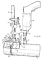
- Mounted on the drill press stand is a drill 51 including a chuck 55 and a borer 53 mounted in the chuck 55. It will be understood that by rotation of the drill press stand handle 45 the drill 51 may be advanced towards or away from the pipe 7. In this way therefore the borer 53 may be brought selectively into contact with the pipe 7.
- the longitudinal relationship between the borer 53 and the platform 9 may be adjusted according to the discussion above with reference to Figure 3. Particularly, therefore, by slackening the coach bolts 39 the longitudinal travel of the casting 37 via elongate holes 35 may be undertaken. This permits the longitudinal location of the borer 53 from the platform 9 along the centre line 23 to be selected by a user of the apparatus. This method of adjustment is also to allow the position of the hole being drilled to be situated as close to the platform 9 as possible. This is desirable so that the clamping force of the four bolts 11 is as near to the pressure point of the borer 53 as is possible. In Figure 4 only two bolt holes 41, three holes 33 and a small part of backplate 1 are visible.
- a distance piece 59 and nut 17 are shown in exploded view.
- the whole assembly 45, 47, 49, 51, 53 and 55 may be removed from the casting 37 by slackening release screws 57 in the casting 37.
- bushes (not shown) may be supplied to suit different pillar sizes for different types of drill press stand.
- the platform 9 no longer couples to a separate backplate. Instead the means for clamping the platform 9 to a pipe 7 to be drilled comprises a member extendible from one portion of the platform to another portion of the platform.
- the member comprises a chain 100 formed from a plurality of metallic links which extends from one side of the platform 102 to another side of the platform 104.
- the platform 9 includes a V-shaped flange member 106 which is equivalent to the base member 9a, and a U-shaped member 25' which is equivalent to the frame member 25 of Figure 3.
- the U-shaped member 25' is formed integrally with the member 106 although they may be formed as separate members subsequently welded together if desired.
- Each side portion 102, 104 of the platform 9 carries a turret 108.
- a screw threaded member which may be rotated manually by rotatable knobs 110, 112. Rotation of the knobs 110, 112 causes the screw thread to rotate and thereby selectively move up or down (as viewing Figure 6) a detent, in this example a metal hook 114.
- Each end of the chain 100 may be placed over the end of each hook 114 and thereby the tension in the chain may be adjusted for clamping the pipe 7 by the tension in the chain on either side of the V groove 106 (the portion 102 and portion 104). It will be apparent that only one of the hooks 114 needs to be attached to a screw thread member adjustable by its respective knob 110 or 112. It is advantageous that both turrets 108 include an adjustable screw thread member, but this is not imperative.
- the platform 9 has formed therein a plurality of elongate holes 35.
- the casting 37 is allowed to travel longitudinally along the holes 35 by way of coach bolts 116 passing through the casting 37 and into the platform 9 in the same manner as with respect to the embodiment of Figures 1 to 4.
- the coach bolts 116 may be adjustable by rotatable knobs 118 formed on the upper surface thereof. By rotating the knobs 118 the tension placed upon the casting 37 by the coach bolts 116 may be adjusted and in this manner therefore the casting 37 may travel along the elongate holes 35, as has been discussed hereabove.
Landscapes
- Engineering & Computer Science (AREA)
- Mechanical Engineering (AREA)
- Drilling And Boring (AREA)
Claims (11)
- Vorrichtung für das Montieren einer Bohrmaschine an einem Rohr, um das Rohr radial zu bohren, die aufweist:
eine Plattform (9); eine Einrichtung (1, 11, 13, 17; 100, 114, 108, 110, 112) für das Festklemmen der Plattform (9) an einem zu bohrenden Rohr (7); und eine Einrichtung für das Montieren eines Säulenbohrmaschinenständers (47) auf der Plattform (9), dadurch gekennzeichnet, daß die Einrichtung für das Montieren des Säulenbohrmaschinenständers (47) auf der Plattform (9) eine Einrichtung (35, 39, 37; 35, 116, 37) für das Regulieren der Position des Säulenbohrmaschinenständers (47) relativ zur Plattform (9) in einer Richtung parallel zur Längsachse des zu bohrenden Rohres (7) aufweist. - Vorrichtung nach Anspruch 1, bei der die Einrichtung für das Festklemmen der Plattform (9) an einem zu bohrenden Rohr (7) aufweist: eine Montageplatte (2), die so geformt ist, daß sie an das Rohr (7) paßt; und eine Einrichtung (11, 13, 17) für das Befestigen der Plattform (9) an der Montageplatte (2), wobei das Rohr (7) sandwichartig dazwischen angeordnet wird.
- Vorrichtung nach Anspruch 1, bei der die Einrichtung für das Festklemmen der Plattform (9) an einem zu bohrenden Rohr (7) ein Element (100) aufweist, das von einem Abschnitt (102) der Plattform (9) zu einem anderen Abschnitt (104) der Plattform (9) ausziehbar ist, und das lösbar mit beiden Abschnitten (102, 104) davon verbunden werden kann, wobei das Element (100) mindestens um einen Teilweg um den Außenumfang des Rohres (7) herum verläuft, wodurch die Plattform (9) am Rohr (7) festgeklemmt wird.
- Vorrichtung nach Anspruch 3, bei der die Plattform (9) ein V-förmiges Element (106) umfaßt, das an ein zu bohrendes Rohr (7) anstößt.
- Vorrichtung nach Anspruch 3 oder Anspruch 4, bei der ein und/oder der andere Abschnitt (102, 104) der Plattform (9) eine Einrichtung (100, 114, 108, 110, 112) für das Regulieren der Spannung im Element (100) umfaßt.
- Vorrichtung nach Anspruch 5, bei der die Einrichtung für das Regulieren der Spannung eine mit Schraubengewinde versehene Arretierung aufweist.
- Vorrichtung nach einem der vorhergehenden Ansprüche, bei der die Einrichtung für das Montieren des Säulenbohrmaschinenständers (47) auf der Plattform (9) ein Säulengehäuse (37) für das Aufnehmen der Säule (49) des Säulenbohrmaschinenständers (47) aufweist.
- Vorrichtung nach einem der vorhergehenden Ansprüche, bei der der Säulenbohrmaschinenständer (47) mittels Schrauben (39, 116) montiert wird, die sich durch Langlöcher (35) in der Plattform (9) erstrecken, um zu gestatten, daß der Säulenbohrmaschinenständer (47) relativ zur Plattform (9) verschiebbar reguliert wird.
- Vorrichtung nach einem der Ansprüche 3 bis 6, bei der das Element (100) eine Kette aufweist.
- In Verbindung einen Säulenbohrmaschinenständer (47) und eine Vorrichtung nach einem der vorhergehenden Ansprüche.
- System für das Bohren von Rohren, das aufweist: eine Bohrmaschine (51); einen Säulenbohrmaschinenständer (47) für die Bohrmaschine (51); und eine Vorrichtung nach einem der Ansprüche 1 bis 10.
Applications Claiming Priority (3)
| Application Number | Priority Date | Filing Date | Title |
|---|---|---|---|
| GBGB9621472.1A GB9621472D0 (en) | 1996-10-15 | 1996-10-15 | Non-magnetic clamping system for drilling pipes for branch tees |
| GB9621472 | 1996-10-15 | ||
| PCT/GB1997/002824 WO1998016353A1 (en) | 1996-10-15 | 1997-10-14 | Apparatus for mounting a drill on a pipe |
Publications (2)
| Publication Number | Publication Date |
|---|---|
| EP0932480A1 EP0932480A1 (de) | 1999-08-04 |
| EP0932480B1 true EP0932480B1 (de) | 2001-01-10 |
Family
ID=10801444
Family Applications (1)
| Application Number | Title | Priority Date | Filing Date |
|---|---|---|---|
| EP97945010A Expired - Lifetime EP0932480B1 (de) | 1996-10-15 | 1997-10-14 | Vorrichtung zur montierung einer bohrmaschine an ein rohr |
Country Status (6)
| Country | Link |
|---|---|
| US (1) | US6050753A (de) |
| EP (1) | EP0932480B1 (de) |
| DE (1) | DE69703892T2 (de) |
| GB (1) | GB9621472D0 (de) |
| WO (1) | WO1998016353A1 (de) |
| ZA (1) | ZA979211B (de) |
Families Citing this family (31)
| Publication number | Priority date | Publication date | Assignee | Title |
|---|---|---|---|---|
| JP4422242B2 (ja) * | 1999-08-26 | 2010-02-24 | 株式会社水研 | 不断水工法 |
| US6264406B1 (en) * | 1999-09-28 | 2001-07-24 | Emerson Electric Co. | Support for mounting a tool on a pipe |
| US20020137433A1 (en) * | 2001-03-26 | 2002-09-26 | Lee Lawrence K. | Abrasive drill bit |
| GB2379405A (en) * | 2001-07-26 | 2003-03-12 | Gordon Henry Turner | Detachable extension apparatus for a frame for mounting a drill on a pipe |
| US7360973B2 (en) | 2001-07-26 | 2008-04-22 | Gordon Henry Turner | Apparatus for mounting a drill on a pipe |
| GB2404161B (en) * | 2003-07-14 | 2007-01-03 | Gordon Henry Turner | Apparatus for mounting a drill on a pipe |
| US7435041B1 (en) | 2005-07-19 | 2008-10-14 | Mcgill Ronald L | Hole cutting assembly for pipes and well casings |
| US8375541B1 (en) | 2006-05-24 | 2013-02-19 | Robert Wisler Beachy | Tool system |
| US20080014035A1 (en) * | 2006-06-30 | 2008-01-17 | Noveon Ip Holdings Corp. | Clamping Tool And Hole Saw Apparatus |
| US8137036B2 (en) * | 2007-12-28 | 2012-03-20 | Sewer Tap Inc. | Coring tool alignment system |
| CA2640498A1 (en) * | 2008-09-30 | 2010-03-30 | George Mckenzie | Apparatus for applying a leverage force to a hand drill |
| US20100089211A1 (en) * | 2008-10-10 | 2010-04-15 | James Rebuck | Adjustable cutting tool |
| WO2010120516A2 (en) | 2009-03-31 | 2010-10-21 | Harry Mcgraw | Method and apparatus of hot tapping multiple coaxial or nested strings of underwater piping and/or tubing for overturned wells or platforms |
| US20110101588A1 (en) * | 2009-11-03 | 2011-05-05 | St Pierre Aaron | Sliding drill press |
| US8770897B2 (en) * | 2009-11-04 | 2014-07-08 | Advanced Drainage Systems, Inc. | Coring tool alignment assembly |
| CN102019452B (zh) * | 2010-12-25 | 2012-05-23 | 石家庄常山纺织股份有限公司 | 一种万向钻台 |
| ES2407030B1 (es) * | 2011-05-19 | 2014-05-09 | Gamesa Innovation & Technology S.L. | Útil de mecanizado. |
| FR2975615B1 (fr) * | 2011-05-23 | 2016-05-20 | Messier Bugatti Dowty | Outillage portatif d'usinage de partie basse d'un caisson d'atterrisseur d'aeronef |
| AU2012100325B4 (en) * | 2012-03-23 | 2012-10-18 | Claude Ernest Nowland | Portable Drill Press |
| US9050669B2 (en) | 2012-10-04 | 2015-06-09 | Illinois Tool Works Inc. | Rapidly retractable tool support for a pipe machining apparatus |
| CN205218121U (zh) | 2013-04-19 | 2016-05-11 | 米沃奇电动工具公司 | 磁力钻床 |
| WO2016144387A1 (en) * | 2015-03-06 | 2016-09-15 | Ridge Tool Company | Hole saw drill guide |
| US10065246B2 (en) * | 2015-04-13 | 2018-09-04 | Illinois Tool Works Inc. | Laser line generator tool for a pipe machining apparatus |
| WO2017037589A1 (en) * | 2015-08-28 | 2017-03-09 | Fellrock Developments Limited | A drilling jig device |
| JP6251439B1 (ja) * | 2017-06-19 | 2017-12-20 | 西田 稔 | 鋼管穴あけ具 |
| US10876517B2 (en) * | 2017-12-22 | 2020-12-29 | Wind Solutions, Llc | Slew ring repair and damage prevention |
| CN108890761A (zh) * | 2018-07-20 | 2018-11-27 | 哈尔滨理工大学 | 一种在大直径薄壁管上热塑性钻孔装置 |
| CN109202132A (zh) * | 2018-11-23 | 2019-01-15 | 广西送变电建设有限责任公司 | 一种冷切削钻孔装置 |
| US11161233B2 (en) * | 2020-01-16 | 2021-11-02 | North Mechanical Contracting Inc. | Vertical drill mount |
| CN113478565A (zh) * | 2021-07-12 | 2021-10-08 | 林耿文 | 一种新材料热熔穿孔装置 |
| ES1303795Y (es) * | 2023-06-15 | 2024-01-10 | Vaquero David Albendea | Soporte para taladros |
Family Cites Families (7)
| Publication number | Priority date | Publication date | Assignee | Title |
|---|---|---|---|---|
| NL222969A (de) * | 1956-12-05 | |||
| US3762829A (en) * | 1971-10-20 | 1973-10-02 | M Yilmaz | Adjustable tool guide and support |
| US3922107A (en) * | 1973-05-31 | 1975-11-25 | Dwight W Fowler | Sewer tapping method and apparatus |
| US4094612A (en) * | 1976-07-29 | 1978-06-13 | Widder Corporation | Tool mounting apparatus |
| US4936720A (en) * | 1989-09-26 | 1990-06-26 | Fend Industrial Tool Inc. | Compact device for cutting holes in pipe |
| US5051044A (en) * | 1990-03-05 | 1991-09-24 | Harold Allen | Pipe drilling apparatus |
| US5713702A (en) * | 1995-04-13 | 1998-02-03 | Turner; Gordon Henry | Adaptors for a drill stand |
-
1996
- 1996-10-15 GB GBGB9621472.1A patent/GB9621472D0/en active Pending
-
1997
- 1997-10-14 EP EP97945010A patent/EP0932480B1/de not_active Expired - Lifetime
- 1997-10-14 US US09/284,729 patent/US6050753A/en not_active Expired - Fee Related
- 1997-10-14 WO PCT/GB1997/002824 patent/WO1998016353A1/en not_active Ceased
- 1997-10-14 DE DE69703892T patent/DE69703892T2/de not_active Expired - Fee Related
- 1997-10-15 ZA ZA9709211A patent/ZA979211B/xx unknown
Also Published As
| Publication number | Publication date |
|---|---|
| GB9621472D0 (en) | 1996-12-04 |
| DE69703892T2 (de) | 2001-06-07 |
| EP0932480A1 (de) | 1999-08-04 |
| DE69703892D1 (de) | 2001-02-15 |
| WO1998016353A1 (en) | 1998-04-23 |
| ZA979211B (en) | 1999-07-15 |
| US6050753A (en) | 2000-04-18 |
Similar Documents
| Publication | Publication Date | Title |
|---|---|---|
| EP0932480B1 (de) | Vorrichtung zur montierung einer bohrmaschine an ein rohr | |
| US5094435A (en) | Flange alignment tool and method | |
| US8550442B2 (en) | Workpiece holding device, system and method | |
| US5560091A (en) | Apparatus for aligning pipe flanges | |
| US7114714B2 (en) | Multifunctional workpiece clamping system | |
| US6568712B1 (en) | Alignment tool for pipe couplings | |
| WO1998016353B1 (en) | Apparatus for mounting a drill on a pipe | |
| US20050172769A1 (en) | Portable vise and saw combination | |
| US4936720A (en) | Compact device for cutting holes in pipe | |
| US6761511B2 (en) | Apparatus for mounting a drill on a pipe | |
| US4825513A (en) | Modular adjustable clamp system | |
| US5651519A (en) | Robot dress bar | |
| US5348428A (en) | Underfloor drilling jig and frame | |
| US5383636A (en) | Bracket system for mounting a cable splicing tool to a pedestal | |
| US20050173853A1 (en) | Portable vise | |
| CN117161744B (zh) | 一种运载火箭整流罩型架对接工装及对接方法 | |
| EP0100421A2 (de) | Bohrständer | |
| RU2632043C2 (ru) | Устройство для механической обработки клапанов и способ механической обработки клапана | |
| JPH0748884Y2 (ja) | サブアッシー用圧締具 | |
| WO1998003310A1 (en) | Tube welding fixture and heat shield | |
| US4153322A (en) | Keyhole grounding clamp | |
| EP1767905A1 (de) | Vorrichtung und Verfahren zum Montieren einer Längenmesseinrichtung auf einer Werkzeugmaschine | |
| EP1446268B1 (de) | Vorrichtung und verfahren zur befestigung eines werkzeugs an einer werkzeugmontageplatte an einem industrieroboter | |
| EP0958894A2 (de) | Hefthammer | |
| CN119934930B (zh) | 一种起动机定子外壳检测工装 |
Legal Events
| Date | Code | Title | Description |
|---|---|---|---|
| PUAI | Public reference made under article 153(3) epc to a published international application that has entered the european phase |
Free format text: ORIGINAL CODE: 0009012 |
|
| 17P | Request for examination filed |
Effective date: 19990510 |
|
| AK | Designated contracting states |
Kind code of ref document: A1 Designated state(s): DE FR GB IT |
|
| GRAG | Despatch of communication of intention to grant |
Free format text: ORIGINAL CODE: EPIDOS AGRA |
|
| 17Q | First examination report despatched |
Effective date: 20000316 |
|
| GRAG | Despatch of communication of intention to grant |
Free format text: ORIGINAL CODE: EPIDOS AGRA |
|
| GRAH | Despatch of communication of intention to grant a patent |
Free format text: ORIGINAL CODE: EPIDOS IGRA |
|
| GRAH | Despatch of communication of intention to grant a patent |
Free format text: ORIGINAL CODE: EPIDOS IGRA |
|
| GRAA | (expected) grant |
Free format text: ORIGINAL CODE: 0009210 |
|
| ITF | It: translation for a ep patent filed | ||
| AK | Designated contracting states |
Kind code of ref document: B1 Designated state(s): DE FR GB IT |
|
| REF | Corresponds to: |
Ref document number: 69703892 Country of ref document: DE Date of ref document: 20010215 |
|
| ET | Fr: translation filed | ||
| PLBE | No opposition filed within time limit |
Free format text: ORIGINAL CODE: 0009261 |
|
| STAA | Information on the status of an ep patent application or granted ep patent |
Free format text: STATUS: NO OPPOSITION FILED WITHIN TIME LIMIT |
|
| REG | Reference to a national code |
Ref country code: GB Ref legal event code: IF02 |
|
| 26N | No opposition filed | ||
| PGFP | Annual fee paid to national office [announced via postgrant information from national office to epo] |
Ref country code: GB Payment date: 20051130 Year of fee payment: 9 |
|
| GBPC | Gb: european patent ceased through non-payment of renewal fee |
Effective date: 20061014 |
|
| PG25 | Lapsed in a contracting state [announced via postgrant information from national office to epo] |
Ref country code: GB Free format text: LAPSE BECAUSE OF NON-PAYMENT OF DUE FEES Effective date: 20061014 |
|
| PGFP | Annual fee paid to national office [announced via postgrant information from national office to epo] |
Ref country code: DE Payment date: 20071011 Year of fee payment: 11 |
|
| PGFP | Annual fee paid to national office [announced via postgrant information from national office to epo] |
Ref country code: IT Payment date: 20071027 Year of fee payment: 11 |
|
| PGFP | Annual fee paid to national office [announced via postgrant information from national office to epo] |
Ref country code: FR Payment date: 20071009 Year of fee payment: 11 |
|
| REG | Reference to a national code |
Ref country code: FR Ref legal event code: ST Effective date: 20090630 |
|
| PG25 | Lapsed in a contracting state [announced via postgrant information from national office to epo] |
Ref country code: IT Free format text: LAPSE BECAUSE OF NON-PAYMENT OF DUE FEES Effective date: 20081014 Ref country code: DE Free format text: LAPSE BECAUSE OF NON-PAYMENT OF DUE FEES Effective date: 20090501 |
|
| PG25 | Lapsed in a contracting state [announced via postgrant information from national office to epo] |
Ref country code: FR Free format text: LAPSE BECAUSE OF NON-PAYMENT OF DUE FEES Effective date: 20081031 |