EP0932508B1 - Radzierblende und verriegelung - Google Patents
Radzierblende und verriegelung Download PDFInfo
- Publication number
- EP0932508B1 EP0932508B1 EP97913777A EP97913777A EP0932508B1 EP 0932508 B1 EP0932508 B1 EP 0932508B1 EP 97913777 A EP97913777 A EP 97913777A EP 97913777 A EP97913777 A EP 97913777A EP 0932508 B1 EP0932508 B1 EP 0932508B1
- Authority
- EP
- European Patent Office
- Prior art keywords
- rim
- appliqué
- flange
- radial side
- assembly
- Prior art date
- Legal status (The legal status is an assumption and is not a legal conclusion. Google has not performed a legal analysis and makes no representation as to the accuracy of the status listed.)
- Expired - Lifetime
Links
- 239000000853 adhesive Substances 0.000 claims description 28
- 230000001070 adhesive effect Effects 0.000 claims description 28
- 241000239290 Araneae Species 0.000 claims description 26
- 238000004381 surface treatment Methods 0.000 claims description 9
- 230000002093 peripheral effect Effects 0.000 claims description 6
- 229910052751 metal Inorganic materials 0.000 claims description 2
- 239000002184 metal Substances 0.000 claims description 2
- VYZAMTAEIAYCRO-UHFFFAOYSA-N Chromium Chemical compound [Cr] VYZAMTAEIAYCRO-UHFFFAOYSA-N 0.000 description 7
- 229910000831 Steel Inorganic materials 0.000 description 6
- 239000000463 material Substances 0.000 description 6
- 238000007747 plating Methods 0.000 description 6
- 239000010959 steel Substances 0.000 description 6
- 239000011324 bead Substances 0.000 description 5
- 238000000034 method Methods 0.000 description 4
- 239000004411 aluminium Substances 0.000 description 3
- 229910052782 aluminium Inorganic materials 0.000 description 3
- XAGFODPZIPBFFR-UHFFFAOYSA-N aluminium Chemical compound [Al] XAGFODPZIPBFFR-UHFFFAOYSA-N 0.000 description 3
- 239000004593 Epoxy Substances 0.000 description 2
- 229910052804 chromium Inorganic materials 0.000 description 2
- 239000011651 chromium Substances 0.000 description 2
- 230000000694 effects Effects 0.000 description 2
- JEIPFZHSYJVQDO-UHFFFAOYSA-N iron(III) oxide Inorganic materials O=[Fe]O[Fe]=O JEIPFZHSYJVQDO-UHFFFAOYSA-N 0.000 description 2
- 239000010935 stainless steel Substances 0.000 description 2
- 229910001220 stainless steel Inorganic materials 0.000 description 2
- 238000013022 venting Methods 0.000 description 2
- 229910000838 Al alloy Inorganic materials 0.000 description 1
- 229910000975 Carbon steel Inorganic materials 0.000 description 1
- 230000001680 brushing effect Effects 0.000 description 1
- 239000002131 composite material Substances 0.000 description 1
- 230000006835 compression Effects 0.000 description 1
- 238000007906 compression Methods 0.000 description 1
- 230000001010 compromised effect Effects 0.000 description 1
- 238000010276 construction Methods 0.000 description 1
- 238000001035 drying Methods 0.000 description 1
- 239000000428 dust Substances 0.000 description 1
- 238000009713 electroplating Methods 0.000 description 1
- 238000005516 engineering process Methods 0.000 description 1
- 230000002349 favourable effect Effects 0.000 description 1
- 239000003292 glue Substances 0.000 description 1
- 208000014674 injury Diseases 0.000 description 1
- 239000007769 metal material Substances 0.000 description 1
- 239000000203 mixture Substances 0.000 description 1
- 238000012986 modification Methods 0.000 description 1
- 230000004048 modification Effects 0.000 description 1
- 238000010422 painting Methods 0.000 description 1
- 238000002360 preparation method Methods 0.000 description 1
- 238000003825 pressing Methods 0.000 description 1
- 230000000630 rising effect Effects 0.000 description 1
- 238000007789 sealing Methods 0.000 description 1
- 238000009987 spinning Methods 0.000 description 1
- 239000000126 substance Substances 0.000 description 1
- 230000008733 trauma Effects 0.000 description 1
- 238000009966 trimming Methods 0.000 description 1
Images

Classifications
-
- B—PERFORMING OPERATIONS; TRANSPORTING
- B60—VEHICLES IN GENERAL
- B60B—VEHICLE WHEELS; CASTORS; AXLES FOR WHEELS OR CASTORS; INCREASING WHEEL ADHESION
- B60B7/00—Wheel cover discs, rings, or the like, for ornamenting, protecting, venting, or obscuring, wholly or in part, the wheel body, rim, hub, or tyre sidewall, e.g. wheel cover discs, wheel cover discs with cooling fins
- B60B7/0013—Hub caps
-
- B—PERFORMING OPERATIONS; TRANSPORTING
- B60—VEHICLES IN GENERAL
- B60B—VEHICLE WHEELS; CASTORS; AXLES FOR WHEELS OR CASTORS; INCREASING WHEEL ADHESION
- B60B7/00—Wheel cover discs, rings, or the like, for ornamenting, protecting, venting, or obscuring, wholly or in part, the wheel body, rim, hub, or tyre sidewall, e.g. wheel cover discs, wheel cover discs with cooling fins
- B60B7/0026—Wheel cover discs, rings, or the like, for ornamenting, protecting, venting, or obscuring, wholly or in part, the wheel body, rim, hub, or tyre sidewall, e.g. wheel cover discs, wheel cover discs with cooling fins characterised by the surface
- B60B7/0033—Wheel cover discs, rings, or the like, for ornamenting, protecting, venting, or obscuring, wholly or in part, the wheel body, rim, hub, or tyre sidewall, e.g. wheel cover discs, wheel cover discs with cooling fins characterised by the surface the dominant aspect being the surface appearance
- B60B7/004—Wheel cover discs, rings, or the like, for ornamenting, protecting, venting, or obscuring, wholly or in part, the wheel body, rim, hub, or tyre sidewall, e.g. wheel cover discs, wheel cover discs with cooling fins characterised by the surface the dominant aspect being the surface appearance the surface being painted
-
- B—PERFORMING OPERATIONS; TRANSPORTING
- B60—VEHICLES IN GENERAL
- B60B—VEHICLE WHEELS; CASTORS; AXLES FOR WHEELS OR CASTORS; INCREASING WHEEL ADHESION
- B60B7/00—Wheel cover discs, rings, or the like, for ornamenting, protecting, venting, or obscuring, wholly or in part, the wheel body, rim, hub, or tyre sidewall, e.g. wheel cover discs, wheel cover discs with cooling fins
- B60B7/0026—Wheel cover discs, rings, or the like, for ornamenting, protecting, venting, or obscuring, wholly or in part, the wheel body, rim, hub, or tyre sidewall, e.g. wheel cover discs, wheel cover discs with cooling fins characterised by the surface
- B60B7/0033—Wheel cover discs, rings, or the like, for ornamenting, protecting, venting, or obscuring, wholly or in part, the wheel body, rim, hub, or tyre sidewall, e.g. wheel cover discs, wheel cover discs with cooling fins characterised by the surface the dominant aspect being the surface appearance
- B60B7/0046—Wheel cover discs, rings, or the like, for ornamenting, protecting, venting, or obscuring, wholly or in part, the wheel body, rim, hub, or tyre sidewall, e.g. wheel cover discs, wheel cover discs with cooling fins characterised by the surface the dominant aspect being the surface appearance the surface being plated or coated
-
- B—PERFORMING OPERATIONS; TRANSPORTING
- B60—VEHICLES IN GENERAL
- B60B—VEHICLE WHEELS; CASTORS; AXLES FOR WHEELS OR CASTORS; INCREASING WHEEL ADHESION
- B60B7/00—Wheel cover discs, rings, or the like, for ornamenting, protecting, venting, or obscuring, wholly or in part, the wheel body, rim, hub, or tyre sidewall, e.g. wheel cover discs, wheel cover discs with cooling fins
- B60B7/02—Wheel cover discs, rings, or the like, for ornamenting, protecting, venting, or obscuring, wholly or in part, the wheel body, rim, hub, or tyre sidewall, e.g. wheel cover discs, wheel cover discs with cooling fins made essentially in one part
-
- B—PERFORMING OPERATIONS; TRANSPORTING
- B60—VEHICLES IN GENERAL
- B60B—VEHICLE WHEELS; CASTORS; AXLES FOR WHEELS OR CASTORS; INCREASING WHEEL ADHESION
- B60B7/00—Wheel cover discs, rings, or the like, for ornamenting, protecting, venting, or obscuring, wholly or in part, the wheel body, rim, hub, or tyre sidewall, e.g. wheel cover discs, wheel cover discs with cooling fins
- B60B7/06—Fastening arrangements therefor
- B60B7/061—Fastening arrangements therefor characterised by the part of the wheels to which the discs, rings or the like are mounted
- B60B7/063—Fastening arrangements therefor characterised by the part of the wheels to which the discs, rings or the like are mounted to the rim
-
- B—PERFORMING OPERATIONS; TRANSPORTING
- B60—VEHICLES IN GENERAL
- B60B—VEHICLE WHEELS; CASTORS; AXLES FOR WHEELS OR CASTORS; INCREASING WHEEL ADHESION
- B60B7/00—Wheel cover discs, rings, or the like, for ornamenting, protecting, venting, or obscuring, wholly or in part, the wheel body, rim, hub, or tyre sidewall, e.g. wheel cover discs, wheel cover discs with cooling fins
- B60B7/06—Fastening arrangements therefor
- B60B7/061—Fastening arrangements therefor characterised by the part of the wheels to which the discs, rings or the like are mounted
- B60B7/065—Fastening arrangements therefor characterised by the part of the wheels to which the discs, rings or the like are mounted to the disc
-
- B—PERFORMING OPERATIONS; TRANSPORTING
- B60—VEHICLES IN GENERAL
- B60B—VEHICLE WHEELS; CASTORS; AXLES FOR WHEELS OR CASTORS; INCREASING WHEEL ADHESION
- B60B7/00—Wheel cover discs, rings, or the like, for ornamenting, protecting, venting, or obscuring, wholly or in part, the wheel body, rim, hub, or tyre sidewall, e.g. wheel cover discs, wheel cover discs with cooling fins
- B60B7/06—Fastening arrangements therefor
- B60B7/061—Fastening arrangements therefor characterised by the part of the wheels to which the discs, rings or the like are mounted
- B60B7/066—Fastening arrangements therefor characterised by the part of the wheels to which the discs, rings or the like are mounted to the hub
-
- B—PERFORMING OPERATIONS; TRANSPORTING
- B60—VEHICLES IN GENERAL
- B60B—VEHICLE WHEELS; CASTORS; AXLES FOR WHEELS OR CASTORS; INCREASING WHEEL ADHESION
- B60B7/00—Wheel cover discs, rings, or the like, for ornamenting, protecting, venting, or obscuring, wholly or in part, the wheel body, rim, hub, or tyre sidewall, e.g. wheel cover discs, wheel cover discs with cooling fins
- B60B7/06—Fastening arrangements therefor
- B60B7/061—Fastening arrangements therefor characterised by the part of the wheels to which the discs, rings or the like are mounted
- B60B7/068—Fastening arrangements therefor characterised by the part of the wheels to which the discs, rings or the like are mounted to the wheel bolts or wheel nuts
-
- B—PERFORMING OPERATIONS; TRANSPORTING
- B60—VEHICLES IN GENERAL
- B60B—VEHICLE WHEELS; CASTORS; AXLES FOR WHEELS OR CASTORS; INCREASING WHEEL ADHESION
- B60B7/00—Wheel cover discs, rings, or the like, for ornamenting, protecting, venting, or obscuring, wholly or in part, the wheel body, rim, hub, or tyre sidewall, e.g. wheel cover discs, wheel cover discs with cooling fins
- B60B7/06—Fastening arrangements therefor
- B60B7/08—Fastening arrangements therefor having gripping elements consisting of formations integral with the cover
-
- B—PERFORMING OPERATIONS; TRANSPORTING
- B60—VEHICLES IN GENERAL
- B60B—VEHICLE WHEELS; CASTORS; AXLES FOR WHEELS OR CASTORS; INCREASING WHEEL ADHESION
- B60B7/00—Wheel cover discs, rings, or the like, for ornamenting, protecting, venting, or obscuring, wholly or in part, the wheel body, rim, hub, or tyre sidewall, e.g. wheel cover discs, wheel cover discs with cooling fins
- B60B7/06—Fastening arrangements therefor
- B60B7/14—Fastening arrangements therefor comprising screw-threaded means
Definitions
- the invention relates to vehicle wheels of the type having an ornamental appliqué secured over the wheel for aesthetic purposes.
- a wheel cover fixing device which includes a spring bias set of tongue pieces which are discrete elements that include the rising edge and groove.
- An annular spring co-operates with the plurality of tongue pieces to bias them to clamp against the wheel rim.
- US-A-5595423 discloses the use of a spinning tool which forms or bonds the outer peripheral edge of the wheel cover to the wheel rim.
- Any wheel assembly having a permanent ornamental surface treatment There should be access to the lug nuts. Tire mounting/demounting machinery should be able to operate without damaging the ornamental surface treatment.
- the wheel assembly should be capable of receiving the standard clip-on balance weights at the rim flanges. There can be no loose components which would cause vibration and noise.
- the ornamental surface treatment should be secured so that it will not become accidentally disassembled or stolen.
- the wheel assembly should be durable so that it will not rust or corrode.
- the permanent ornamental surface treatment should be economical relative to other prior art surface treatments and ornamentation.
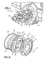
- a vehicular wheel assembly according to the subject invention is generally shown at 10 in the Figures. Throughout the different embodiments, like members are shown with like reference numerals, different embodiments being distinguished by the use ofprimed numerals.
- the wheel assembly 10 includes a wheel 12 and an appliqué 14 which provides a permanent ornamental surface treatment, such as chrome-plated stainless steel.
- the wheel 12 includes an annular rim 16, defining a central axis A.
- the rim 16 includes a pair of rim flanges 18 (see Figure 2) spaced on opposite sides of a well portion 20, over which a standard tube-type or tubeless tire 22 is mounted.
- a bead seat radius 24 is interposed between each of the rim flanges 18 and the well portion 20 for retaining the tire beads (not shown) of the tire 22.
- United States Patent 5,368,370 assigned to the assignee hereof, is incorporated by reference to provide additional information of common wheel designs and basic teachings of the appliqué.
- the bead seat radius 24 is on the outward radial side 23 of the rim flanges 18 with the inward radial side 25 provided on the wheel face.
- a spider 26 is concentrically fixed within the rim 16 for connecting to a rotating hub 28.
- the spider 26 generally includes a plurality of spokes 30 which radiate from a center section 32 to a spoke flange 34. Venting spaces 36 are interposed between adjacent spokes 30.
- the spoke flange 34 interconnects with the rim 16.
- well-established distinctions may become somewhat obscured in some type of wheels, such as the cast "full face” type, with the spider 26 extending integrally into the outer rim flange 18.
- any type of wheel face design can be used. In the illustrated embodiment of Figures 1 and 2, an aluminium wheel is shown, though any material wheel may be used with the subject invention.
- a weld line 38 may be present at the outer bead seat radius 24, such as in a steel wheel of the full face type, as illustrated in Figure 3.
- the effect of the weld line is that considerable surface disturbance is created on the visible side of the wheel assembly 10, in the area of the rim flange 18 and the spoke flange 34.
- extensive surface preparation of this area of the wheel would be required due to the trauma induced by the weld line.
- chrome plating inherently amplifies all surface flaws, extra care would normally be required to prepare this area adjacent the weld line 38 prior to chrome plating the wheel.
- the center section 32 of the spider 26 includes a center hole 40 for receiving the protruding portion of the hub 28 and its dust cap.
- various cap or cover 42 options are available for aesthetically trimming the center hole 40.
- the cover 42 for a steel wheel is generally frustroconical.
- the cover 42 for an aluminium wheel is a flat plate-like member. It should also be appreciated that different designs of wheel appliqués 14 may not require or utilize a hub 28.
- lug stud holes 44 Disposed circumferentially about the center hole 40 are a plurality of lug stud holes 44. Standard threaded lug studs 46 extending from the hub 28 pass through the holes 44. As commonly known, lug nuts 48 are threaded onto the studs 46 to secure the wheel assembly 10 to the hub 28.
- the rim 16 and the spider 26 sections of the assembly 10 are manufactured from fabricated or cast aluminium as illustrated in both Figures 1 and 2.
- the rim 16 and spider 26 sections can be manufactured from fabricated steel or any other material commonly known in the art.
- the wheel assembly 10 includes the ornamental appliqué 14 formed of a uniform thickness material, such as sheet steel or stainless steel.
- the appliqué 14 overlaps the rim 16, the spider 26 and rim flange 18 to present an ornamental surface treatment to the visible outer portions of the assembly 10.
- the appliqué 14 has an annular outer connecting portion 50 disposed adjacent the outer rim flange 18 and the spoke flange 34 of the spider 26.
- the appliqué 14 also includes an annular inner connecting portion 52 generally overlying at least a portion of the center section 32.
- the appliqué 14 also includes an extension flange portion 54 which wraps around the rim flange 18.
- the appliqué 14 includes a plurality of vent openings 56 aligned between the spokes 30 of the spider 26 of the wheel 12.
- the vent openings 56 are radially positioned between the inner 52 and the outer 50 connecting portions of the appliqué 14.
- the vent openings 56 correspond with the vent spaces 36 of the wheel 12.
- the vent openings 56 may vary from the spoke 40 configuration so that different and unique ornamental designs can be achieved. In some cases, the number of vent openings 56 need not be equal to the number of vent spaces 36.
- the appliqué 14 further includes a locking member 60 in the outer connecting portion 50 for mechanically locking the appliqué 14 to the rim flange 18.
- the locking member 60 maintains the appliqué 14 in pressing, compressive contact with adhesive 70 to ensure proper adhesion and thereby prevent the appliqué 14 from becoming disconnected from the rim 16 and spider 26 during operation.
- the locking members 60 also maintain the appliqué 14 to the wheel 12 when little or no adhesive 70 is utilized.
- the locking member 60 includes an annular rim catch or shoulder 62 formed in the inward radial side 25 of the rim flange 18.
- An annular locking shoulder 64 of the outer connecting portion 50 of the appliqué 14 engages the annular rim catch 62 to hold the appliqué 14 in place while the adhesive 70 cures, and thereafter.
- the locking shoulder 64 is forced into engagement behind the catch 62 so that a spring-like pressure is exerted against the adhesive 70 by the appliqué 14.
- extension flange portion 54 Extending from the locking shoulder 64 is the extension flange portion 54 which extends along the rim 16, through a bend, and extends over the top of the rim flange 18 to encase the rim flange 14 (U-shaped) as illustrated in Figures 3 and 4, or alternatively, at least over the peripheral edge of the rim flange 14 toward the outward radial side 23 (L-shaped) (not shown).
- the edge of the extension flange portion 54 abuts or lies within a rim relief area 66 and adjacent a rim shoulder 68, provided in the outward radial side 23 to provide a somewhat flush or level surface between the extension flange 54 and inner rim 16.
- the extension flange 54 provides further decorative appearance of the spider and rim by disallowing the edge of the rim flange 18 to be visually exposed.
- the rim 16 in this portion may discolor or corrode (rust) distorting the decorative appearance of the wheel appliqué or appliqué 14.
- the wheel appliqué 14 may be slid over the wheel and pressed to allow the locking shoulder 64 to snap against the catch 62 to retain the appliqué 14, with the extension flange portion 54 encasing the rim flange 18.
- the appliqué 14 may also include a plastically deformed section 80 inserted through a plurality of retainer openings 82 in the inner connecting portion 52 ( Figure 3) as discussed in United States Patent 5,368,370 issued November 29, 1994,
- the inner connecting portion 52 of the appliqué 14 may or may not extend radially inwardly as far as the lug and stud holes 44. If the inner connecting portion 52 extends over the lug stud holes 44, corresponding apertures 72 are aligned over each of the lug stud holes 44 to permit passage of the studs 46.
- the specific configuration of the cap 42 determines the inward extend of the inner connecting portion 52.
- Figure 2 shows an embodiment of the invention where the inner connecting portion 52 does not extend over the lug stud holes 44, because the cap 42 completely covers the lug nuts 48.
- a cross section of one spoke 30 is shown with the overlying portion of the appliqué 14.
- appliqué 14 extends into the vent opening 56, radially inwardly of the spokes 30.
- the entire outboard or visible surface of the wheel is covered by the appliqué 14 in the preferred embodiment. It may be desirable to cover only a portion of the wheel 12.
- the full coverage feature of the preferred construction further rigidifies the appliqué 14, eliminates sharp edges to prevent cuts, and also helps seal or protect the adhesive 70 from direct contact with debris and the elements. This further helps prevent the appliqué 14 from rotating upon the spider 26 and assists in the alignment of the appliqué 14 over the spider 26 during assembly.
- the adhesive 70 of substantially uniform thickness is provided for permanently bonding the appliqué 14 to the rim 16 and the spider 26 along overlapping surface areas.
- the adhesive 70 is an epoxy material applied in a tacky, uncured condition between the wheel 12 and appliqué 14.
- the adhesive 70 comprises an epoxy material, there is naturally a required drying or curing time.
- the adhesive 70 may be applied. to the inner surface of the appliqué 14 or the outer surface of the wheel face, i.e. the rim 16 and spider 26.
- the thickness of the adhesive 70 is less than twice the thickness of the appliqué 14.
- the locking member 60 compresses the adhesive between the appliqué 14 and wheel 12 to allow curing of the adhesive 70 and for further securement thereof.
- the adhesive 70 may comprise double-sided tape or the like. Regardless of the specific adhesive 70 employed, it must be heat resistant so that its holding power is not compromised under high heat conditions.
- the adhesive 70 is generally provided in the area of the inner and outer connecting portions 52, 50.
- the extension flange portion 54 may or may not utilize adhesive 70 which will not effect the securement of the appliqué 14 to the wheel.
- a bead of adhesive 70 may be placed at the tip of the rim flange 18 near the inside and/or outside comers thereof which is compressed upon assembly.
- the subject wheel assembly 10 is formed by the steps of forming the annular rim 16 with a pair of rim flanges 18, forming the spider 26 with a plurality of spokes 30 and interposed venting spaces 36, supporting the spider 26 concentrically within the rim 16, preforming an ornamental appliqué 14 with annular outer and inner connecting portions 50, 52 and the extension flange portion 54, applying an adhesive 70 between the appliqué 14 and rim 16, positioning the appliqué 14 centrally over the spider 26 and the rim 16 and around the rim flanges 18 while aligning the appliqué vent openings 56 in the spaces between the spokes 30, compressing the adhesive 70 into a substantially uniformly thick space between the appliqué 14 and the spider 26, and mechanically maintaining the compressing step until the adhesive 70 is set.
- the steps of forming the applique 14 includes forming the inner and outer connecting portions 52, 50 with the vent openings 56 and forming the extension flange 54 as a generally L or U-shape to slide over the rim flange 18. Thereafter, the applique 14 is snapped onto the wheel 12.
- the step of mechanically maintaining the adhesive 70 in compression between the applique 14 and the spider 26 and the rim 16 includes forming an annular catch 62 in the outer rim flange 18, and force fitting the locking shoulder 64 of the applique 14 into the catch 62.
- the method further includes plating the applique 14 with a metallic composition containing a percentage of chromium prior to positioning the applique over the spider 26 and rim 16. This plating step is accomplished using well-known electro-plating technology.
- the subject wheel assembly 10 as constructed in accordance with the preferred embodiment described above creates a functional and durable composite wheel assembly 10 having a permanent ornamental chromium surface treatment at a relatively low cost.
- the wheel assembly 10 is constructed to permit access of tire mounting equipment and the normal inclusion of balance weights about the rim flanges 18. Further, the assembly 10 is permanently fixed so as to preclude theft of components or accidental loss ofthe appliqué 14. Further, the full surface adhesive 70 fixation technique creates an assembly 10 which will not vibrate between the appliqué 14 and the remainder of the assembly 10.
- the ornamental appliqué 34 may be of steel or other metal material, but may also be of plastic with a finished decorative outer surface. Such plastic surfaces have been either chrome plated, painted, etc.
- the appliqué 14 is fabricated from a uniform thickness material in a stamping or die forming operation. It will be readily appreciated that such a forming technique is quick, easy and relatively inexpensive.
- the extension flange portion 54 and locking shoulder 64 may be formed in the same die forming operation with tools and dies.
- the outer and inner connecting portions 50, 52 may be die formed and the locking shoulder 64 and extension flange 54 being contoured by a spun forming process.
- Various types of surface finishing may be utilized, such as chrome plating, painting, metal brushing, etc.
- the adhesive 70 may be used, but is also possible to omit the adhesive 70 due to the locking shoulder 64. The adhesive 70 is useful also in sealing the area behind the wheel appliqué 14 and to the spider 26.
- the shape and decorative design of the wheel appliqué 14 may vary and may either cover some of the wheel apertures or vents, as desired. Furthermore, additional fasteners may be utilized to fasten the wheel appliqué to the wheel directly at the center. In this case, the inner connecting portion 52 extends inwardly as far as the lug stud holes 44, and provides clearance for the lug stud fasteners 48. Also, separate fasteners may be placed through apertures between the lug stud holes from the backside into apertures in the wheel appliqué to secure the wheel appliqué to the wheel directly. It is to be appreciated that other designs of wheel appliqués would be encompassed with the teachings herein.
Landscapes
- Engineering & Computer Science (AREA)
- Mechanical Engineering (AREA)
- Vehicle Interior And Exterior Ornaments, Soundproofing, And Insulation (AREA)
- Steering Controls (AREA)
- Lubricants (AREA)
- Tires In General (AREA)
- Connection Of Plates (AREA)
- Chemically Coating (AREA)
Claims (9)
- Fahrzeugradanordnung (107) mit einer behandelten Zieroberfläche (14), wobei die Anordnung folgendes aufweist:dadurch gekennzeichnet, daß der ringförmige äußere Verbindungsbereich (50) ein Arretierelement (60) enthält, um die Zierblende (14) an der inneren Radialseite (25) des Felgenhorns (18) mit der ringförmigen Felge (16) zu verriegeln.eine ringförmige Felge (16), die eine Mittelachse (A) bildet und ein Felgenhorn (18) hat, das sich zu einem peripheren Felgenrand erstreckt, der eine äußere Radialseite (23) der ringförmigen Felge und eine innere Radialseite (25) der ringförmigen Felge (16) voneinander trennt, wobei die äußere Radialseite (23) der inneren Radialseite (25) gegenüberliegt und diese durch den dazwischen befindlichen peripheren Felgenrand miteinander verbunden sind;einen Stern (26), der konzentrisch innerhalb der Felge (16) angebracht ist, um eine Verbindung mit einer sich drehende Nabe (28) herzustellen;eine Zierblende (14), die die innere Radialseite (25) der Felge sowie den Stern (26) und das Felgenhorn (18) überlappt;wobei die Zierblende (14) einen ringförmigen äußeren Verbindungsbereich (50), der der inneren Radialseite (25) des Felgenhorns benachbart angeordnet ist, einen ringförmigen inneren Verbindungsbereich (52), der dem Stern (26) benachbart angeordnet ist, sowie einen Verlängerungsflansch (54) aufweist, der sich radial nach außen über den ringförmigen äußeren Verbindungsbereich (50) hinaus sowie über das Felgenhorn (18) erstreckt, um den peripheren Felgenrand zu überdecken, und der sich bis auf die äußere Radialseite (23) des Felgenhorns erstreckt, wobei der Verlängerungsflansch in Umfangsrichtung der Zierblende im wesentlichen kontinuierlich ausgebildet ist,
- Anordnung nach Anspruch 1,
wobei der Verlängerungsflansch (54) sich über den peripheren Felgenrand des Felgenhorns (18) sowie angrenzend an die äußere Radialseite (23) erstreckt. - Anordnung nach Anspruch 2,
wobei der Verlängerungsflansch (54) sich entlang der äußeren Radialseite (23) das Felgenhorn entlang erstreckt. - Anordnung nach Anspruch 3,
wobei das Arretierelement (60) eine ringförmige Arretiereinrichtung (62) aufweist, die in der inneren Radialseite (25) des Felgenhorns ausgebildet ist. - Anordnung nach Anspruch 4,
wobei das Arretierelement (60) eine Arretierschulter (64) aufweist, die in dem äußeren Verbindungsbereich (50) ausgebildet ist und mit der ringförmigen Arretiereinrichtung (62) zusammenwirkt. - Anordnung nach Anspruch 3,
wobei die äußere Radialseite (23) des Felgenhorns eine Aussparung (66) aufweist und sich der Verlängerungsflansch (54) der Blende in der Aussparung erstreckt. - Anordnung nach Anspruch 6,
wobei die äußere Radialseite (23) des Felgenhorns angrenzend an die Aussparung (66) eine Flanschschulter (68) angrenzend an das Ende des Verlängerungsflansches aufweist. - Anordnung nach Anspruch 1,
wobei ferner ein Klebstoff zwischen der Zierblende (14) und mindestens einem Element aus der Felge oder dem Stern vorhanden ist. - Anordnung nach Anspruch 1,
wobei die Zierblende (14) ein Metallblech-Stanzteil aufweist.
Applications Claiming Priority (5)
| Application Number | Priority Date | Filing Date | Title |
|---|---|---|---|
| US2965496P | 1996-10-28 | 1996-10-28 | |
| US29654P | 1996-10-28 | ||
| US08/863,965 US5829843A (en) | 1996-10-28 | 1997-05-27 | Wheel applique and lock |
| US863965 | 1997-05-27 | ||
| PCT/US1997/019358 WO1998018638A1 (en) | 1996-10-28 | 1997-10-22 | Wheel applique and lock |
Publications (3)
| Publication Number | Publication Date |
|---|---|
| EP0932508A1 EP0932508A1 (de) | 1999-08-04 |
| EP0932508A4 EP0932508A4 (de) | 2002-04-17 |
| EP0932508B1 true EP0932508B1 (de) | 2005-03-16 |
Family
ID=26705197
Family Applications (1)
| Application Number | Title | Priority Date | Filing Date |
|---|---|---|---|
| EP97913777A Expired - Lifetime EP0932508B1 (de) | 1996-10-28 | 1997-10-22 | Radzierblende und verriegelung |
Country Status (8)
| Country | Link |
|---|---|
| US (1) | US5829843A (de) |
| EP (1) | EP0932508B1 (de) |
| JP (1) | JP3847792B2 (de) |
| AU (1) | AU726615B2 (de) |
| BR (1) | BR9712685A (de) |
| DE (1) | DE69732782T2 (de) |
| ES (1) | ES2241045T3 (de) |
| WO (1) | WO1998018638A1 (de) |
Families Citing this family (25)
| Publication number | Priority date | Publication date | Assignee | Title |
|---|---|---|---|---|
| US5435631A (en) * | 1994-02-28 | 1995-07-25 | Hayes Wheels International, Inc. | Vehicle wheel cover retention system |
| JP2001521853A (ja) * | 1997-10-31 | 2001-11-13 | ヘイズ、レマズ、インタナシャナル、インク | 自動車車輪及びそれを作る方法 |
| US6406100B1 (en) * | 1998-10-30 | 2002-06-18 | Hayes Lemmerz International, Inc. | Vehicle wheel cover retention system and method for producing same |
| US6609763B1 (en) * | 1997-10-31 | 2003-08-26 | Hayes Lemmerz International, Inc. | Vehicle wheel cover retention system and method for producing same |
| WO1999041091A2 (en) * | 1998-02-11 | 1999-08-19 | Hayes Lemmerz International, Inc. | Vehicle wheel cover retention system and method for producing same |
| US6152538A (en) * | 1998-04-17 | 2000-11-28 | Mckechnie Vehicle Components (Usa), Inc. | Mechanical locks for wheel covers |
| US7494192B2 (en) | 1998-05-06 | 2009-02-24 | Lacks Industries, Inc. | Vehicle wheel rim flange and overlay assembly |
| BR9916611A (pt) * | 1998-12-31 | 2001-11-20 | Hayes Lemmerz Int Inc | Sistema de retenção de tampa de roda de veìculo emétodo para produzir o mesmo |
| US6779852B2 (en) | 2001-04-19 | 2004-08-24 | Lacks Industries, Inc. | Composite wheel assembly and method for producing same |
| BR0201514B1 (pt) * | 2002-04-30 | 2010-08-10 | roda e peça de revestmento. | |
| JP3929904B2 (ja) * | 2003-01-30 | 2007-06-13 | 株式会社アルティア橋本 | 装飾フィルムが貼着された車両用装飾成形品 |
| US6932435B2 (en) * | 2003-11-07 | 2005-08-23 | Mckechnie Vehicle Components (Usa), Inc. | Adhesive patterns for vehicle wheel assemblies |
| US6991299B2 (en) * | 2004-02-18 | 2006-01-31 | Lacks Enterprises, Inc. | Vehicle wheel assembly and cladding therefore |
| DE102004017554A1 (de) * | 2004-04-07 | 2005-11-03 | Ise Innomotive Systems Europe Gmbh | Radzierblende |
| US7264316B2 (en) | 2004-08-27 | 2007-09-04 | Mckechnie Vehicle Components (Usa), Inc. | Shield for wheel assemblies |
| US20060043782A1 (en) * | 2004-09-02 | 2006-03-02 | Houten Garry V | Vehicle wheel and overlay assembly |
| US7448695B1 (en) | 2005-10-20 | 2008-11-11 | Hayes Lemmerz International, Inc. | Vehicle wheel cover retention system and method for producing same |
| US7452037B1 (en) * | 2006-12-26 | 2008-11-18 | Mitchell Nunes | Alloy wheel with mating wheel cover |
| WO2011006033A2 (en) * | 2009-07-10 | 2011-01-13 | Mckechnie Vehicle Components | Use of resist coating to enhance adhesion of wheel claddings |
| US8919890B2 (en) | 2009-11-02 | 2014-12-30 | Segiu Anca | Wheel with increased interior lip depth |
| US9707800B2 (en) * | 2013-03-15 | 2017-07-18 | Lacks Enterprises, Inc. | Partial wheel cladding |
| US10116610B2 (en) | 2016-08-31 | 2018-10-30 | Keystone Automotive Operations, Inc. | Automotive wheel overlay attachment system |
| CN110712469B (zh) * | 2019-10-08 | 2021-05-18 | 广西正源电机有限公司 | 一种端盖外置轻便型轮毂电机动力车轮 |
| WO2021154340A1 (en) * | 2020-01-30 | 2021-08-05 | Howmet Aerospace Inc. | Vehicle wheels and methods of making vehicle wheels |
| GB2597074A (en) | 2020-07-14 | 2022-01-19 | Daimler Ag | Wheel cover for a motor vehicle |
Family Cites Families (27)
| Publication number | Priority date | Publication date | Assignee | Title |
|---|---|---|---|---|
| US1858228A (en) * | 1930-07-11 | 1932-05-10 | Lyon George Albert | Means for ornamenting rims |
| US1985378A (en) * | 1932-01-16 | 1934-12-25 | Lyon George Albert | Construction for ornamenting rims |
| US2965496A (en) | 1959-02-27 | 1960-12-20 | Paul E Serdar | Food package |
| US3517968A (en) * | 1968-10-09 | 1970-06-30 | Motor Wheel Corp | Wheel rim trim ring |
| US3726566A (en) | 1970-01-02 | 1973-04-10 | Et Ind | Wheel structure |
| US3669501A (en) * | 1970-03-03 | 1972-06-13 | Motor Wheel Corp | Vehicle wheel construction |
| US3918762A (en) * | 1974-03-29 | 1975-11-11 | Goodyear Tire & Rubber | Vehicle wheel cover |
| DE2813412A1 (de) * | 1978-03-29 | 1979-10-04 | Porsche Ag | Felge eines kraftfahrzeugrades, insbesondere aus aluminiumdruckguss |
| US4344654A (en) * | 1979-01-29 | 1982-08-17 | Apezynski Frederick A | Wheel trim retention |
| US4251476A (en) * | 1979-03-16 | 1981-02-17 | Motor Wheel Corporation | Manufacture of ornamental vehicle wheels |
| US4270805A (en) * | 1979-04-06 | 1981-06-02 | Spisak Edward G | Wheel and hub cap assembly |
| US4659148A (en) * | 1985-09-23 | 1987-04-21 | Motor Wheel Corporation | Vehicle wheel construction |
| JPS6412902A (en) * | 1987-07-06 | 1989-01-17 | Kanto Seiki Co | Wheel cover fixing device |
| US4874206A (en) * | 1987-12-07 | 1989-10-17 | Sampson Thomas J | Tire wheel and wheel cover spray shield and kit |
| US5098272A (en) * | 1989-05-01 | 1992-03-24 | Motor Wheel Corporation | Apparatus for molding composite metal-elastomer wheels |
| US4976497A (en) * | 1989-05-17 | 1990-12-11 | Motor Wheel Corporation | Vehicle wheel construction |
| US5128085A (en) * | 1989-05-17 | 1992-07-07 | Motor Wheel Corporation | Method of making a composite styled wheel |
| US5143426A (en) * | 1989-11-13 | 1992-09-01 | Masco Industries, Inc. | Vehicle wheel construction |
| US5031966A (en) * | 1989-11-24 | 1991-07-16 | Oakey Douglas L | Wheel cover |
| US5131727A (en) * | 1990-11-16 | 1992-07-21 | Johnson Harold M | Aerodynamic wheel cover |
| JP2893366B2 (ja) * | 1992-06-25 | 1999-05-17 | ラックス・インダストリイズ・インコーポレーテッド | オーバ・レイ |
| US5368370A (en) * | 1993-09-03 | 1994-11-29 | Thompson International | Vehicle wheel construction |
| US5595423A (en) * | 1994-02-28 | 1997-01-21 | Hayes Wheels International, Inc. | Vehicle wheel cover retention system and method for producing same |
| US5664845A (en) * | 1994-02-28 | 1997-09-09 | Hayes Wheels International, Inc | Vehicle wheel cover retention system and method for producing same |
| US5435631A (en) * | 1994-02-28 | 1995-07-25 | Hayes Wheels International, Inc. | Vehicle wheel cover retention system |
| US5597213A (en) * | 1995-06-06 | 1997-01-28 | Lacks Industries, Inc. | Wheel and overlay assembly |
| US5820225A (en) | 1996-10-28 | 1998-10-13 | Mckechnie Vehicle Components (Usa), Inc. | Vehicle wheel assembly and method of making same |
-
1997
- 1997-05-27 US US08/863,965 patent/US5829843A/en not_active Expired - Lifetime
- 1997-10-22 DE DE69732782T patent/DE69732782T2/de not_active Expired - Fee Related
- 1997-10-22 EP EP97913777A patent/EP0932508B1/de not_active Expired - Lifetime
- 1997-10-22 AU AU50886/98A patent/AU726615B2/en not_active Ceased
- 1997-10-22 WO PCT/US1997/019358 patent/WO1998018638A1/en not_active Ceased
- 1997-10-22 ES ES97913777T patent/ES2241045T3/es not_active Expired - Lifetime
- 1997-10-22 JP JP52064198A patent/JP3847792B2/ja not_active Expired - Fee Related
- 1997-10-22 BR BR9712685-3A patent/BR9712685A/pt not_active IP Right Cessation
Also Published As
| Publication number | Publication date |
|---|---|
| BR9712685A (pt) | 1999-12-14 |
| US5829843A (en) | 1998-11-03 |
| EP0932508A1 (de) | 1999-08-04 |
| JP2001502993A (ja) | 2001-03-06 |
| JP3847792B2 (ja) | 2006-11-22 |
| WO1998018638A1 (en) | 1998-05-07 |
| AU726615B2 (en) | 2000-11-16 |
| DE69732782T2 (de) | 2006-04-06 |
| ES2241045T3 (es) | 2005-10-16 |
| EP0932508A4 (de) | 2002-04-17 |
| DE69732782D1 (de) | 2005-04-21 |
| AU5088698A (en) | 1998-05-22 |
Similar Documents
| Publication | Publication Date | Title |
|---|---|---|
| EP0932508B1 (de) | Radzierblende und verriegelung | |
| EP0785875B1 (de) | Fahrzeugradaufbau | |
| EP0932507B1 (de) | Fahrzeugradanordnung und herstellungsverfahren | |
| US5921634A (en) | Wheel applique and lock | |
| US6637832B2 (en) | Wheel and cladding | |
| US6554371B2 (en) | Vehicle wheel cover retention system | |
| US6502308B1 (en) | Vehicle wheel cover retention system and method for producing same | |
| JP2002362102A (ja) | 複合ホイール組立体及びその製造方法 | |
| US8052223B2 (en) | Multi-piece vehicle wheel cover retention system and method for producing same | |
| USRE42140E1 (en) | Vehicle wheel cover retention system and method for producing same | |
| US8162406B2 (en) | Multi-piece vehicle wheel cover retention system and method for producing same | |
| US20120007415A1 (en) | Multi-piece vehicle wheel cover retention system and method for producing same | |
| US7300116B2 (en) | Center lock wheel cover | |
| EP0956977B1 (de) | Mechanische Verriegelung für Radzierblenden | |
| US6609763B1 (en) | Vehicle wheel cover retention system and method for producing same | |
| US20060071539A1 (en) | Clad wheel assembly | |
| US6932435B2 (en) | Adhesive patterns for vehicle wheel assemblies | |
| KR100233800B1 (ko) | 차량 휘일 구조체 | |
| JP2510030Y2 (ja) | 3ピ―ス型の自動車用ホイ―ル | |
| WO1999022948A1 (en) | Vehicle wheel cover retention system and method for producing same |
Legal Events
| Date | Code | Title | Description |
|---|---|---|---|
| PUAI | Public reference made under article 153(3) epc to a published international application that has entered the european phase |
Free format text: ORIGINAL CODE: 0009012 |
|
| 17P | Request for examination filed |
Effective date: 19990512 |
|
| AK | Designated contracting states |
Kind code of ref document: A1 Designated state(s): DE ES FR GB IT |
|
| A4 | Supplementary search report drawn up and despatched |
Effective date: 20020304 |
|
| AK | Designated contracting states |
Kind code of ref document: A4 Designated state(s): DE ES FR GB IT |
|
| 17Q | First examination report despatched |
Effective date: 20030527 |
|
| GRAP | Despatch of communication of intention to grant a patent |
Free format text: ORIGINAL CODE: EPIDOSNIGR1 |
|
| RIC1 | Information provided on ipc code assigned before grant |
Ipc: 7B 60B 7/02 B Ipc: 7B 60B 7/06 A |
|
| RIC1 | Information provided on ipc code assigned before grant |
Ipc: 7B 60B 7/02 B Ipc: 7B 60B 7/06 A |
|
| GRAS | Grant fee paid |
Free format text: ORIGINAL CODE: EPIDOSNIGR3 |
|
| GRAA | (expected) grant |
Free format text: ORIGINAL CODE: 0009210 |
|
| AK | Designated contracting states |
Kind code of ref document: B1 Designated state(s): DE ES FR GB IT |
|
| REG | Reference to a national code |
Ref country code: GB Ref legal event code: FG4D |
|
| REF | Corresponds to: |
Ref document number: 69732782 Country of ref document: DE Date of ref document: 20050421 Kind code of ref document: P |
|
| REG | Reference to a national code |
Ref country code: ES Ref legal event code: FG2A Ref document number: 2241045 Country of ref document: ES Kind code of ref document: T3 |
|
| PLBE | No opposition filed within time limit |
Free format text: ORIGINAL CODE: 0009261 |
|
| STAA | Information on the status of an ep patent application or granted ep patent |
Free format text: STATUS: NO OPPOSITION FILED WITHIN TIME LIMIT |
|
| 26N | No opposition filed |
Effective date: 20051219 |
|
| ET | Fr: translation filed | ||
| PGFP | Annual fee paid to national office [announced via postgrant information from national office to epo] |
Ref country code: ES Payment date: 20071026 Year of fee payment: 11 Ref country code: DE Payment date: 20071130 Year of fee payment: 11 |
|
| PGFP | Annual fee paid to national office [announced via postgrant information from national office to epo] |
Ref country code: IT Payment date: 20071029 Year of fee payment: 11 |
|
| PGFP | Annual fee paid to national office [announced via postgrant information from national office to epo] |
Ref country code: GB Payment date: 20071029 Year of fee payment: 11 Ref country code: FR Payment date: 20071017 Year of fee payment: 11 |
|
| GBPC | Gb: european patent ceased through non-payment of renewal fee |
Effective date: 20081022 |
|
| REG | Reference to a national code |
Ref country code: FR Ref legal event code: ST Effective date: 20090630 |
|
| PG25 | Lapsed in a contracting state [announced via postgrant information from national office to epo] |
Ref country code: IT Free format text: LAPSE BECAUSE OF NON-PAYMENT OF DUE FEES Effective date: 20081022 Ref country code: DE Free format text: LAPSE BECAUSE OF NON-PAYMENT OF DUE FEES Effective date: 20090501 |
|
| PG25 | Lapsed in a contracting state [announced via postgrant information from national office to epo] |
Ref country code: FR Free format text: LAPSE BECAUSE OF NON-PAYMENT OF DUE FEES Effective date: 20081031 |
|
| PG25 | Lapsed in a contracting state [announced via postgrant information from national office to epo] |
Ref country code: GB Free format text: LAPSE BECAUSE OF NON-PAYMENT OF DUE FEES Effective date: 20081022 |
|
| REG | Reference to a national code |
Ref country code: ES Ref legal event code: FD2A Effective date: 20081023 |
|
| PG25 | Lapsed in a contracting state [announced via postgrant information from national office to epo] |
Ref country code: ES Free format text: LAPSE BECAUSE OF NON-PAYMENT OF DUE FEES Effective date: 20081023 |